1
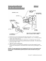
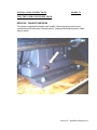
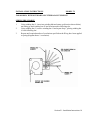
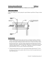
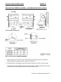
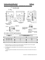
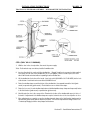
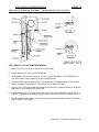
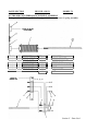
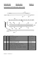
190-002-.doc
July 2001
RE-COIL-AWAY 70 DOOR
OWNERS MANUAL
WITH DOOR-MOUNTED
OUTBOARD
COUNTERBALANCE SPRINGS
OR SPRINGLESS DESIGN WITH INERTIA BRAKE
Serial No.:
Contents:
* Description of Components
* Warranty
* Framing Detail
* Installation Instructions
* Maintenance
* Troubleshooting
* Parts List
975-A OLD NORCROSS ROAD
LAWRENCEVILLE, GA 30045
(770) 338-5000 TEL
(770) 338-5034 FAX
(877) 925-2468 TOLL FREE
190-002-.doc
July 2001
RE-COIL-AWAY 70 DOOR
OWNERS MANUAL
WITH DOOR-MOUNTED
OUTBOARD
COUNTERBALANCE SPRINGS
OR SPRINGLESS DESIGN WITH INERTIA BRAKE
Serial No.:
Contents:
* Description of Components
* Framing Details
* Installation Instructions
975-A OLD NORCROSS ROAD
LAWRENCEVILLE, GA 30045
(770) 338-5000 TEL
(770) 338-5034 FAX
(877) 925-2468 TOLL FREE
DESCRIPTION OF COMPONENTS
MODEL 70
CURTAIN
The entire curtain is composed of 1/4" thick Styrene Butadiene Rubber (SBR) with an
additional thickness of rubber attached vertically on each side of the curtain. The inner
side of this additional rubber segment is bevelled to form the patented windlok
action within the guides. Polyethylene fabric strips (PET weave) are bonded to the
bevelled edges of the windloks to minimize friction within the guides should significant
wind or air pressure build up on the curtain during operation. The top edge of the
curtain is secured to the drive barrel thus providing the coiling action which raises and
lowers the curtain.
DRIVE BARREL
(for models with outboard springs)
The drive barrel consists of a steel tube and a drive shaft at each end. Steel
inserts enclose the ends of the drive barrel and provide support for both drive shafts.
(for models with springless design)
The drive barrel consists of a steel tube containing a free shaft at one end and a
drive shaft at the opposite end. Steel inserts enclose the ends of the drive barrel and
provide support for both the free and drive shafts.
DRIVE END BRACKET
The drive end bracket supports the drive shaft which is inserted into a bearing in
the centre of the drive end bracket. A mounting angle is then bolted to the back of the
drive end bracket, thus securing it to the face of the opening.
SPRING OR FREE END BRACKET
The spring/free end bracket supports the drive shaft which is inserted into a
bearing in the centre of the spring/free end bracket. A mounting angle is then bolted to
the back of the end bracket, thus securing it to the face of the opening.
OUTBOARD COUNTERBALANCING SPRING
Assembly could consist of one to six spring assemblies.
The outboard counterbalance spring assembly is supported by a flange bearing
at each end. A pair of sprockets and roller chain connects the outboard counterbalance
spring to the drive barrel. Tension is applied from the torsion springs during the closing
cycle, thus providing a counterbalanced curtain. A cover is optional for protection
and/or appearance.
SPRINGLESS WITH INERTIA BRAKE
Door sizes which are less than or equal to 150 square feet in size do not require
a stop lock bearing unless specifically required for safety purposes. All door size over
150 square feet are standard with stop lock bearing. The inertia brake is attached to the
free-end bracket and is keyed to the free-end shaft. This safety device is designed to
lock the free-end shaft and the drive barrel should the door free-fall.
Section I – Component Description 1
DESCRIPTION OF COMPONENTS
MODEL 70
INERTIA BRAKE (cont’d)
The ratchet wheel and control disc are fixed and driven by the shaft. The scanning
roll which is mounted on the pawl is moved up and down by the control disc. The pawl
passed between the teeth of the ratchet wheel without touching them. If the trip speed is
exceeded, the scanning roll lifts and the pawl grips into the teeth of the ratchet wheel. The
shaft is slowed down by the damping bar which is made of non-corrosive and thermally
stable high grade steel.
It is impossible to operate the safety device when the damping bar is distorted (bent).
This is ensured by a spring which locks the catch and the ratchet wheel. The damping bar has
to be replaced or bent to its original shape before the safety device can be reused. It is not
possible to operate the door electrically when the safety device is activated. A disconnect
switch interrupts the control circuit of the operator when the damping bar is bent. The door
can be opened if operator is equipped with a manual opening feature (e.g. chain hoist, crank
handle).
The Self-Aligning Bearing
A safety device can be used as the bearing for
one side of the shaft. It has the characteristics
of a self-aligning ball bearing. Therefore, the
safety device too is a bearing swinging around
the axis of symmetry of the stub shaft. When
the bearing is beyond the middle, there will be
shear and lateral movement. The effect is
additional load on the shaft and the safety
device.
The Patented Damping Bar
The highest shock load on the door and its mounting is
when the shaft locks during free-fall. The resultant
forces are too high for the rolling shutter. With a safety
device from ELEKTROMATEN with patented damping
bar you can forget all these problems. When catching
the falling door, the damping bar is distorted
“softly”(there will be no load which can damage the
door). The kinetic energy of the falling door is
transformed into bending energy.
The additional load during the crash is limited to 1.6 x
standard load. Without damping, it would be 10 x
higher. Therefore, safety devices without a damping
bar do not eliminate shock load!
Section I – Component Description 2
DESCRIPTION OF COMPONENTS
MODEL 70
INERTIA BRAKE (cont’d)
The Ratchet (Catch)
In the event of failure of one of the holding parts
(gearing, brake system, drive chain), the rolling shutter
will go into a “free-fall”.
The speed of rotation increases until the releasing
speed is reached. Now the scanning roll takes off
from the control disc and the pawl grips into the
engaged position. The falling door is stopped when
the pawl grips into the ratchet wheel and the shaft is
locked.
The resultant forces are no longer transferred from the
“sensitive” ball bearing of the ratchet (catch) to the
damping bar. They are guided by a large steel bolt
which supports the ratchet. The ball bearing will not
be damaged by the impact.
The safety device will remain intact after arresting
the door. It can be used again after replacement of
the damping bar.
The Electrical Disconnect
After the safety device has been activated, it is
impossible to operate the door electronically until
the distorted damping bar is replaced. Before
changing the damping bar, locate the cause of the
problem and repair the defect.
There may be different reasons for the release of
the safety device. It is not always caused by a
broken gear or drive chain. Its operation can be
initiated by a loose chain, defective or fading brakes,
displaced lath or damaged tracks.
Section I – Component Description 3
DESCRIPTION OF COMPONENTS
MODEL 70
IDLER BARREL
The idler barrel is located just below the drive barrel and is attached to the end
brackets by the shafts at either end of the idler barrel which are inserted into the bearings
provided at the base (and near the back) of each end bracket. The rubber curtain is
maintained between the idler barrel and the wall above the lintel, thus ensuring minimal air
loss.
GUIDES
The guides are composed of pre-assembled lengths of structural steel which, when
positioned vertically on either side of the opening, provide an enclosed channel for each side
of the curtain, thus completing the “windlok” feature. The front and back sections of the
guides are hinged together to allow the curtain to be easily re-inserted into the guides after
severe impacts.
FACTORY SUPPLIED MOUNTING STEEL (Optional Feature)
Some door systems are supplied from the factory with the guides and plate angles
welded to mounting steel. This mounting steel may consist of the flat bar or rectangle tube as
prescribed on the framing detail or it may be a special design to incorporate a travelling
windbar recessed into the jambs. In all of these instances, follow the instructions in the
Installation Section for Guides.
WINDING HUB (for models with outboard spring assembly only)
The winding hub is used to apply tension to the torsion springs on the outboard
counterbalance spring assembly. The winding hub on the end of the spring assembly contains
a series of holes for the insertion of a tension rod and set screws to retain the desired tension.
BOTTOM BAR
The bottom bar of the curtain is reinforced with structural steel angle and flat bar
which are bolted together to resist the natural bending action of the curtain and to maintain it
parallel with the floor. The bottom bar is also equipped with a centre ‘break-away’ feature
which provides easy straightening in case it is bent under impact. Door widths, greater than
20-feet, are not equipped with this feature.
The underside of the bottom bar is equipped with a flexible reversing edge. The
reversing edge provides an emergency stop and/or instant reverse of the door during the
closing cycle should an obstruction be present in the opening. The reversing edge also
provides a flexible seal between the bottom of the door and the threshold.
ELECTRIC OPERATOR
Model FDGH electric operator with rotary screw-type limit switches, electromechanical disc brake, helical gear reducer and emergency hand chain for manual operation.
Motor and sprockets are to be of capacity to handle either single speed or two-speed
operation.
Section I – Component Description 4
ALBANY DOOR SYSTEMS
Limited Warranty
All door systems manufactured by Albany Door Systems Limited are
warranted from the date of purchase against defects in materials and workmanship as
follows: (i) door systems in general...one (1) year; (ii) rubber curtains (where
applicable)...Lifetime Warranty.
If within this period of time any part is found to be defective, new or remanufactured parts will be furnished free of charge, F.O.B. our plant in Lawrenceville,
GA., provided that recommended installation and maintenance procedures (as outlined in
our Service Manual and Installation Instructions booklet) are followed.
In cases where the manufacturer's warranty of certain parts connected with
our door systems (i.e.: electrical motors, switches, etc.) is less than the Albany warranty,
the manufacturer's warranty will apply.
The Albany warranty does not include replacement of parts due to normal
wear and tear, damage beyond the control of Albany (i.e: damage in transit, impacts, etc.),
or any labour charges incurred in the removal and/or replacement of defective parts.
Warranty claims must be made to Albany (or to the authorized distributor
from whom the purchase was made), and defective parts to be returned for verification or
replacement must be forwarded prepaid to:
ALBANY DOOR SYSTEMS
975-A Old Norcross Rd
Lawrenceville, GA 30045
Alban Door Systems
STATEMENT OF WARRANTY
RE-COIL-AWAY SBR Curtain
LIFETIME WARRANTY ON SBR Curtain material.
Albany Door Systems warrants to the original owner of the door that the door panel fabric and components
(windlock) will be free of defects in material and workmanship for as long as the door is installed in its original
opening or building.
Only defects brought to the attention of Albany Door Systems during the warranty period will be covered by this
warranty.
Albany Door Systems will replace any component parts which are found to be defective upon inspection by an
Albany Door Systems representative.
This warranty does not cover damage caused by collision or other abuse of the product. Adjustments made to the
Control Panel or to the mechanical operation of the door without the authorization of Albany Door Systems will
void this warranty.
The replacement provisions shall be the limit of Albany Door System’s responsibility under this warranty and
Albany Door Systems shall not be responsible for any other losses or damages due to the operation of any door or
parts covered by this warranty.
No other oral or written representations made by Albany Door Systems or its agents are a part of this warranty
unless specifically set forth in writing by an authorized Albany Door Systems official.
THE ABOVE SET FORTH WARRANTY IS SELLER'S SOLE WARRANTY. SELLER MAKES NO
OTHER WARRANTY OF ANY KIND WHATSOEVER, EXPRESSED OR IMPLIED; AND ALL
IMPLIED WARRANTIES OF MERCHANTABILITY AND FITNESS FOR A PARTICULAR
PURPOSE WHICH EXCEED THE AFORESTATED OBLIGATION ARE HEREBY DISCLAIMED BY
SELLER AND EXCLUDED FROM THIS AGREEMENT.
M&ISBR9/99
INSTALLATION INSTRUCTIONS
MODEL 70
Refer to the Framing Detail Drawing and Shop Drawing as required.
FACTORY SUPPLIED MOUNTING STEEL (Optional Feature)
If your door system has been supplied from the factory with the guides and plate angles
welded to mounting steel, please note the following:
1. Follow the standard procedure for mounting the door guides to the wall, however, weld or
fasten the mounting steel rather than the guide.
2. The left and right plate angles have been pre-.mounted; therefore, this step can be
disregarded in the installation.
3. For shipping purposes, the door assembly is fastened to the skid using an additional set of
inside plate angles. When installing the door assembly, remove the back spreader bar that
attaches to these inside plate angles and re-install once the door is in place. Discard the
inside plate angles that were used for shipping. If the door system utilizes double plate
angles (an inside and an outside set), the outside set will be fastened on the skid and must
be mounted with the door assembly and welded to the mounting steel.
4. If the framing steel supplied incorporates the travelling windbar track, disregard the
instructions for mounting the windbar tracks
GUIDES
The guides supplied with this door system are as per Figure #1-1. The top of each guide
front plate have the corners rolled back. They do not require dismantling prior to installation.
Section II – Installation Instructions 1
INSTALLATION INSTRUCTIONS
MODEL 70
GUIDES (cont’d)
As proper placement of the guides is critical to the overall installation of the "Re-CoilAway”, please follow instructions carefully.
1.
Prior to installation, check that the width of the opening matches the width of the
door as ordered for that opening.
2.
Check that the guide mounting steel is plumb (+/- 1/4").
3.
Using a water hose level or transit, check that the underside of the lintel is level
(1/4" tolerance). Measurements from the underside of the lintel to the floor on both
sides of the opening should not vary by more than 1" from the length of the door as
ordered for that opening.
4.
Again, using a water hose level or transit, scribe a horizontal line 6" above the
underside of the lintel on the mounting steel on the left side of the opening (see
Figure #1-2). Continue this horizontal line across the front of the opening and scribe
another line on the mounting steel on the right side of the opening (see Figure #1-2).
If actual measurements or calculations as referred to in Steps 1, 2 or 3 exceed the
tolerance indicated, contact our office before proceeding further with the installation.
5.
Place the "left guide" flush with the inside edge of the mounting steel on the left side
of the opening (see Figure #1-2). Position the top of the guide to correspond with
the scribed line 6" above the underside of the lintel (see Figure #1-2). Ensuring that
the guide is exactly perpendicular, attach it to the mounting steel by fillet welding
(using approximately 12" centres) down the entire length of each side of the guide
where it contacts the mounting steel (see Figure #1-2).
6.
Repeat Step 5 with the "right guide".
7.
The clearance of /2" (+ /16") in the guide opening (see Figure #1-1), which allows
the curtain to move freely within the guides, has been determined at the factory.
However, to ensure that this clearance has not been affected due to rough handling
1
during shipping or erection, simply pass a /2" bolt through the guide opening to
check for possible wide or narrow areas. If any variations are encountered, simply
spread narrow areas open with a pry bar or reduce over-width areas by striking the
outside portion of the guide with a hammer.
8.
Unbolt the hinged portion of both guides so that the curtain can be inserted later.
Erection of the guides is now complete.
1
1
Section II – Installation Instructions 2
INSTALLATION INSTRUCTIONS
MODEL 70
GUIDES (cont’d)
Section II – Installation Instructions 3
INSTALLATION INSTRUCTIONS
MODEL 70
CURTAIN
Inspect the curtain while it is mounted on the pallet (see Figure #2-1) and you will
notice that one end bracket is equipped with an operator mounting plate while the other one is
not. The end bracket with the mounting plate is referred to as the drive end bracket and the
other is referred to as the spring end bracket.
Erection of the curtain (following erection of the guides) should proceed as follows:
1.
Remove the idler barrel from the door by removing the bolts in each end bearing.
Slide the barrel free from the endplates and place aside for later assembly.
2.
Unbolt the two (2) angle pieces attached to each end bracket (thus unbolting them
from the pallet) so they can be mounted on each side of the opening.
Section II – Installation Instructions 4
INSTALLATION INSTRUCTIONS
MODEL 70
CURTAIN (cont'd)
3.
Ensuring they will be mounted on the face of the opening in the same up and down
position as they were mounted on the end brackets (see Figure #2-2), mount the angle
pieces on the mounting steel as follows:
Place the left angle piece so that its outside edge is flush with the outside edge
of the left guide, ensuring at the same time that the bottom edge of the angle
piece rests on the top edge of the left guide that is welded to the mounting
steel (see Figure #2-2).
Weld the inside edge of the angle to the mounting steel, then weld the top edge of the
angle piece, and then plug weld the holes provided in the angle piece (see Figure #22). Do not weld along the outside edge of the angle piece.
Repeat the above procedures with the right angle piece. The opening is now ready for
installation of the curtain.
Section II – Installation Instructions 5
INSTALLATION INSTRUCTIONS
MODEL 70
CURTAIN (cont'd)
4.
The curtain/end bracket assembly may then be lifted into place and the end brackets
re-bolted to the angle pieces mounted on the face of the opening. Caution: Do not
remove the ropes securing the curtain in a rolled-up position. Care should be
taken when lifting the curtain so as not to damage the bottom bar and reversing edge
(if applicable) attached to the bottom of the curtain.
5.
With the curtain now in place, loosen the set screws in the flange bearing at the centre
of the spring and drive end brackets. Center the curtain between the end brackets.
Clearance should be approximately 2". Using a medium grade thread locker, tighten
all set screws.
6.
Check that the top of the two end brackets are level with each other. If levelling is
required, either end bracket may be re-positioned by loosening the bolts that attach
them to the angles and adjusting the bracket up or down within the slotted area
provided.
7.
Some door systems will require bracing from the wall to the end brackets as shown in
Figure #2-3. Depending upon the size of the door, structural angle is supplied from
the factory with door system.
Section II - Installation Instructions 6
INSTALLATION INSTRUCTIONS
MODEL 70
RE-COIL-AWAY SPREADER BAR ADJUSTMENT
The following procedure can be applied for wide doors where the spreader bars may deflect
upward to a point that is either physically or aesthetically unacceptable for hood installation.
1. Cut a wooden spacer (2” x 4”) to fit tightly between the two (2) front spreader bars at
mid-span.
2. Position a lifting mechanism (lift-truck forks or hoist strap) below the bottom spreader
bar at the spacer location and apply a minimal upward force.
3. Loosen all fasteners on the front cross braces.
4. Apply an additional upward force to deflect the spreader bars approximately 2” above
level.
5. Tighten all fasteners on the front cross braces.
6. Remove the lifting mechanism and evaluate the resulting deflection for acceptability.
Section II – Installation Instructions 7
INSTALLATION INSTRUCTIONS
MODEL 70
ELECTRIC OPERATOR MODEL FDGH
1. Install the door sprocket tight against the flange bearing with a ¼” key (supplied).
2. Loosely mount the operator on the drive end plate with the ½ NC x 1-3/4” bolts with flat
washers, lock washers and nuts.
3. Connect the drive chain and adjust the alignment by re-positioning the door sprocket.
4. Set the chain tension using the slots provided in the drive end bracket. The chain should
not have more than ¼” slack.
5. Tighten all operator mounting bolts.
6. Remove the ropes securing the curtain around the drive barrel and manually lower the
curtain to the closed position. Watch that the limit switches do not get damaged by “over
travel”.
CAUTION: The ropes keeping the curtain wrapped on the drive barrel can be removed only if
the drive chain is installed and both guide front plates have been removed from the guide
assemblies.
Section II – Installation Instructions 8
INSTALLATION INSTRUCTIONS
MODEL 70
ELECTRIC OPERATOR MODEL FDGH
IMPORTANT: TRANSPORT PROTECTOR
This operator is supplied with a breather valve installed. Remove transport protector before
commissioning to allow the valve to function properly. Simply pull the transport protector (rubber
strap) to remove.
Section II – Installation Instruction 9
INSTALLATION INSTRUCTIONS
MODEL 70
FOR MODELS WITH OUTBOARD COUNTERBALANCE SPRINGS
SPRING PRE-CHARGE
1.
2.
3.
Using winding bar #1, insert into winding hub and rotate up (direction shown below)
not letting go until winding bar #2 has been inserted in following slot.
Using winding bar #2, remove winding bar #1 and repeat Step 1, placing winding bar
#1 into following slot.
Repeat until required number of revolutions specified on the ID tag have been applied
to spring (diagram shows ¼ revolution).
Section II – Installation Instructions 10
INSTALLATION INSTRUCTIONS
MODEL 70
FOR MODELS WITH OUTBOARD COUNTERBALANCE SPRINGS
STRETCHING SPRING
Using both winding bars, stretch spring the required distance specified on ID tag (as shown
below)
IDLER BARREL
1. Prior to installing the idler barrel, remove the ropes securing the curtain in a rolled-up
position, and by using the manual chain hoist, lower the curtain until it hangs 2" below
the top of the opening. Making sure that the idler barrel is in front of the curtain; lift the
idler barrel into position. Insert the bearing mounting bolts and tighten them into place.
Position the idler barrel so that the main body of the barrel is an equal distance from each
end bracket (approximately 3-1/2 on either side). Tighten the set screws (use a medium
grade thread locker on all set screws) located in each end bearing.
2. Using the manual chain hoist, lower the curtain until it hangs approximately 12" below
the opening, and then close the guides which will in turn secure the curtain and the steel
ends of the bottom bar.
Section II – Installation Instructions 11
INSTALLATION INSTRUCTIONS
MODEL 70
IDLER BARREL (cont’d)
3. Directly behind the idler barrel, check the spacing between the curtain and the back wall.
There should be no more than a maximum of 1/4" and no less than a minimum of 1/8"
clearance between the curtain and the back wall.
To reduce or increase this clearance, the idler barrel can be adjusted by loosening the
bolts on the flange bearings which support the idler barrel on the end brackets. The
slotted holes in the end brackets allow the idler barrel to be moved in the proper direction.
The bolts on the flange bearings can then be tightened to secure the idler barrel in the
correct position. Care should be taken to ensure that the curtain is not being pressed
between the back wall and any point along the length of the idler barrel.
4. As proper tracking of the curtain is essential to trouble-free operation, a final check
should be made at this point to determine if the curtain is positioned at a 90o angle to the
upright guides. This can be accomplished by completely unbolting and opening the front
portion of either the left or right guide and viewing the position of the outer edge of the
curtain as it is lowered with the manual chain hoist. If the curtain tracks to either side as
it is lowered, the raising or lowering of either the spring or drive end bracket will easily
correct any problem of improper tracking. Refer to Page 1 of the Troubleshooting
Section.
After determining that the curtain is at the proper 90o angle, simply re-bolt the front guide
plate into position and, after necessary electrical connections are made to the operator and
control panel along with final adjustments of the "Open" and "Close" limit switches, your
"Re-Coil-Away" Door will be ready for use.
5. Clear plastic film is wrapped around the curtain to prevent soiling of the curtain during
the shipping and installation. This plastic wrap must be removed prior to operating the
door. Removal can be facilitated by manually lowering the door into the closed position.
Section II – Installation Instructions 12
INSTALLATION INSTRUCTIONS
MODEL 70
FOR MODELS WITH OUTBOARD COUNTERBALANCE SPRINGS
LINTEL SEALING STRIP
Every “Re-Coil-Away” Door System is supplied complete with a “Lintel Sealing Strip”, the
purpose of which is to seal the area between the header and the curtain.
To install the lintel sealing strip, use fasteners appropriate to the material used as lintel (or
use ¼” TEK self-tapping screws supplied with each door and located in the hardware carton.
For further details refer to drawings shown below.
Sealing strip holder – length minus door width minus 1”
Sealing strip – length minus door width plus 1”
Fasteners located on 12” centres
LINTEL SEALING STRIP
DRAWING 89 B 015
Section II – Installation Instructions 1
INSTALLATION INSTRUCTIONS
MODEL 70
LIMIT SWITCH ADJUSTMENT
IMPORTANT: MAKE SURE THE TRAVELLING CAMS DO NOT ENGAGE THE LIMIT SWITCH
WHEN USING THE MANUAL CHAIN HOIST.
1. Remove the cover from the limit box located on the electric operator..
2. Use the manual chain hoist to position the bottom of the door approximately 18” below
the lintel.
3. Depress the cam guide plate and turn the left cam until it engages the “open” limit switch
on the left. The switch will click when the contact is made.
4. Insert the cam guide plate into the nearest slot in the cam.
5. Use the manual chain hoist to position the bottom of the door approximately 18” above
the floor.
6. Depress the cam guide plate and turn the right travelling cam until it engages the “close”
limit switch on the right. The switch will click when the contact is made.
7. Insert the cam guide plate into the nearest slot in the cam.
8. The door can now be cycled by the electric operator. Fine tune the travelling cams
between the cycles until acceptable limits are obtained.
Note: Turning either cam away from its respective limit switch will increase door travel.
Section II – Installation Instructions 14
INSTALLATION INSTRUCTIONS
MODEL 70
CONNECTING TO POWER SUPPLY
Consult local electrical codes before proceeding with permanent installation.
WARNING!
Exercise caution when engaging electric operator. The drive and limit chains are
exposed and if turning could cause injury.
Install control panel, etc as required. Make the necessary electrical connections to the
operator and control panel. Wiring diagrams can be found inside the control panel.
On 3-phase units, make certain the operator rotates in the correct direction. If the
direction is wrong, the limit switches will not function and damage could occur. It is
recommended that the door be moved manually to mid-position before turning on the power
so that it may be stopped before damage occurs should rotation be incorrect. If the direction
is wrong, reverse any two (2) of the three (3) incoming power supply leads to correct rotation.
CONNECTION OF A REVERSING EDGE
A separate 24 volt electrical circuit is provided for the connection of a reversing edge.
Any such device that uses a normally open contact may be connected to the two (2) reversing
edge leads on the terminal strip located in the control panel. When the door comes in contact
with an object during downward travel, the circuit causes the motor to stop and/or reverse the
direction of the door.
INERTIA BRAKE WIRING INSTRUCTIONS
INSTALLATION INSTRUCTIONS
Section II – Installation Instructions 15
MODEL 70
INERTIA BRAKE WIRING INSTRUCTIONS (cont’d)
1.
2.
3.
4.
5.
The inertia brake must be wired in series to the hoist interlock switch.
Connect the No. 7 wire coming from the control panel to one wire from the inertia
brake using a marret.
Connect the other wire from the inertia brake to terminal No. 7.
Connect wire No. 8 from the control panel to terminal No. 8 in the limit box.
Refer to wiring diagram and schematic for further details.
INSTALLATION INSTRUCTIONS
Section II – Installation Instructions 16
MODEL 70
TRAVELLING WINDBAR ASSEMBLY
This is an optional accessory item which may not be applicable to model ordered.
Step 1
Drive Barrel Kit Installation
Step 2
Instructions for Guide-Mounted Windbar Assembly
Instructions for Jamb-Mounted Windbar Assembly
Step 3
4” or 4-1/2” Windbar Tube Installation
6-5/8” or 8-5/8” Windbar Tube Installation
Step 4
4” or 4-1/2” Windbar Tube Installation (cont’d)
6-5/8” or 8-5/8” Windbar Tube Installation (cont’d)
Travelling Windbar Part Identification
Section II – Installation Instructions 17
INSTALLATION INSTRUCTIONS
MODEL 70
TRAVELLING WINDBAR ASSEMBLY – DRIVE BARREL
DRIVE BARREL KIT INSTALLATION
DRAWING NO. 94-0432
STEP 1
Note: If your door was supplied from the factory with a Travelling Windbar, proceed directly to Step 2.
1. With the door in the closed position, disconnect the power supply.
2. Determine dimension “A” and “B” from the chart and measure the drive barrel to the required locations.
From these locations, move to the closest centre between curtain fasteners and mark the barrel 2” from the
curtain edge.
3. Drill a ∅ 5/16” and tap 3/8 – 16 into the drive barrel at all locations.
4. Wrap a hold-down bar with the windbar strap (1-1/2 wraps) and pierce a hole through the strap layers that
aligns with the hole in the hold-down bar. Fasten the strap to the drive barrel with a 3/8-16NC x 5/8” LG
BHCS and flat washer. Repeat this procedure with the remaining windbar strap(s).
5. If you are installing a jamb-mount windbar, route the straps over the top of the curtain and down between
the curtain and the bulk head. Check that the straps are not twisted.
If you are installing a guide-mount windbar, feed the strap between the drive barrel and the curtain. This
procedure may require further closing of the door with the manual chain hoist to loosen the curtain tension.
IMPORTANT:
Make sure the travelling cams do not damage the limit switch when using the manual chain hoist for this
procedure.
Section II – Installation Instructions 18
INSTALLATION INSTRUCTIONS
MODEL 70
TRAVELLING WINDBAR ASSEMBLY – WINDBAR TRACK (Guide-Mount)
STEP 2 – RE-COIL-AWAY WITH GUIDE-MOUNTED WINDBAR
If your door was supplied from the factory with a guide-mount 6-5/8” or 8-5/8” Travelling Windbar, proceed
directly to STEP 3
1. If you are installing a 4” or a 4-1/2” O.D. windbar, fasten one (1) windbar track bracket to each hole provided
in the windbar tracks. Orient the windbar track bracket with the slot protruding beyond the track edge
opposite the curve. Fasten each bracket to the track using one (1) 3/8-16NC x 5/8” LG BHCS per bracket.
2. With the door in the open position, disconnect the power supply.
3. There is a left-hand and right-hand windbar track. Determine the appropriate location for each track given
that the curved side is furthest from the curtain and the stop bolt holes are at the bottom.
4. Determine the curtain to windbar track spacing required for your travelling windbar diameter
(4”, 4-1/2”, 6-5/8” or 8-5/8” O.D.).
5. If you are installing a 4” or a 4-1/2” O.D. windbar, unbolt the respective guide fasteners which align with the
mounting brackets. Discard these fasteners and attach the windbar track using the 3/8-16NC x 1-1/2” long
HHCS and nuts provided.
6. If you are installing a 6-5/8” or an 8-5/8” O.D. windbar, position the windbar track to the guies accordingly
and weld each guide bracket to the outside of the guide back plate with two (2) 2” long fillet welds.
Section II – Installation Instructions 19
MODEL 70
INSTALLATION INSTRUCTIONS
TRAVELLING WINDBAR ASSEMBLY – WINDBAR TRACK (Jamb-Mount)
STEP 2 – ALL JAMB-MOUNTED WINDBARS
1. Fasten one (1) windbar track bracket to each hole provided in the two (2) windbar tracks. Orient the
windbar track bracket with the slot protruding beyond the track edge opposie the curve. Fasten the
bracket to the track using one (1) 3/8 – 16 NC x 5/8” long BHCS per bracket.
2. With the door in the open position, disconnect the power supply.
3. There is a left-hand and right-hand windbar track. Determine the appropriate location for each track
given that the curved side is furthest from the curtain and the stop bolt holes are at the bottom.
4. Determine the curtain to windbar track spacing required for your travelling windbar diameter
(4”, 4-1/2”, 6-5/8” or 8-5/8” O.D.).
5. Position the windbar track to the jamb accordingly and weld mounting bracket to the jamb or fasten thru
the slot provided.
Section II – Installation Instructions 20
INSTALLATION INSTRUCTIONS
MODEL 70
TRAVELLING WINDBAR ASSEMBLY – WINDBAR TUBE INSTALLATION
STEP 3 - FOR 4” OR 4-1/2” DIAMETER WINDBARS
1. Determine dimensions “C” and “D” from the chart and mark the lintel (jamb mount) or the spreader bar
(guide mount) at these dimensions from the outside of the end plates.
2. If installing a jamb-mounted windbar, weld a lintel bracket at each mark on the lintel, 6” from the curtain.
If installing a guide-mounted windbar, temporarily centre and clamp a “windbar strap clamp” at the specified
location on the lower front spreader bar to match drill the 5/16” diameter holes.
Section II – Installation Instructions 21
INSTALLATION INSTRUCTIONS
MODEL 70
TRAVELLING WINDBAR ASSEMBLY – WINDBAR TUBE INSTALLATION
STEP 3 (FOR 6-5/8” OR 8-5/8” DIAMETER WINDBARS)
OPENING WIDTH
(O.W.)
O.W. <= 120’’
120‘’ < O.W. <= 180’’
180‘’ < O.W. <= 240’’
240‘’ < O.W. <= 300’’
300‘’ < O.W. <= 360’’
360‘’ < O.W. <= 480’’
DISTANCE FROM OUTSIDE OF ENDPLATE
TO STRAP LOCATION
DIM ‘C’
DIM ‘D’
9 ‘’
S/O
18’’
S/O
36’’
S/O
18’’
42’’
27’’
48’’
33’’
60’’
1. Determine dimensions “C” and “D” from the chart and mark the lintel (jamb-mount) or the truss (guidemount) at these dimensions from the outside of the end plates.
2. If installing a jamb-mounted windbar, weld a ratchet buckle at each mark on the lintel, 9” from the curtain
(see Detail B).
If installing a guide-mounted windbar, weld a ratchet buckle at each mark on the bottom of the truss (see
Detail A).
Section II – Installation Instructions 22
INSTALLATION INSTRUCTIONS
MODEL 70
TRAVELLING WINDBAR ASSEMBLY – WINDBAR TUBE INSTALLATION
STEP 4 (FOR 4” OR 4-1/2” WINDBARS)
1. With the door in the closed position, disconnect the power supply.
*Note: Roller wheels may come factory-installed in windbar tube.
2. Insert a roller wheel into each end of the windbar tube. “Snuggly” install a set screw and nut (nut supplied
as a spacer) in both ends of the windbar tube (do not over-tighten). With set screws in place, the roller
wheels will extend and retract without separating from the windbar tube.
3. Lift the windbar into the bottom of the tracks. Insert a stop bold (3/8-16NC x 3-1/2” LG HHCS) into the hole
at the bottom of each track and secure with a 3/8-16NC hex nut.
4. Route the windbar straps around the bottom of the windbar tube, then upward towards the lintel (jambmount) or spreader bar (guide-mount). Check that there are no twists in the straps.
5. Route the loose end of each windbar strap between individual windbar strap clamps and temporarily fasten
to the lintel bracket (jamb-mount) or spreader bar (guide-mount).
6. Carefully raise the door to the open position. Examine the location of the windbar with respect to the to of
its tracks. If adjustments to the windbar straps are required, return the door to the closed position to do so.
7. Once adjustments are complete, secure the windbar strap and clamps to the lintel bracket (jamb-mount) or
spreader bar (guide-mount) with the fasteners provided. Trim excess strap material leaving at least 1-1/2”
of extra strap hanging below the strap clamps and fasteners.
Section II – Installation Instructions 23
INSTALLATION INSTRUCTIONS
MODEL 70
TRAVELLING WINDBAR ASSEMBLY – WINDBAR TUBE INSTALLATION
STEP 4 (FOR 6-5/8” OR 8-5/8” DIAMETER WINDBARS)
1. With the door in the closed position, disconnect the power supply.
2. Insert a roller wheel into each end of the windbar tube.
3. Lift the windbar into the bottom of the tracks. Insert one stop bolt (3/8-16NC x 3-1/2” LG HHCS) into the
holes at the bottom of each track and secure with 3/8-16NC hex nuts.
4. Route the windbar straps around the bottom of the windbar tube, then upward towards the lintel for jambmount or spring truss for guide-mount. Check that there are no twists in the straps.
5. Route the loose end of each windbar strap through the slot in the spool of individual ratchets on the lintel for
jamb-mount or on the spring truss for guide-mount.
6. Carefully raise the door to the open position, examine the location of the windbar with respect to the top of
its tracks. If adjustments to the windbar straps are required, return the door to the closed position to do so.
7. Once the adjustments are complete, trim excess strap material, leaving a minimum of three (3) full wraps of
strap on the spool of the ratchets.
Section II – Installation Instructions 24
INSTALLATION INSTRUCTIONS
MODEL 70
TRAVELLING WINDBAR ASSEMBLY – PART IDENTIFICATION
Description:
Travelling Windbar – 1 Required
Application:
Description:
Door Width <= 20’ use 4” O.D. tube
Door Width > 20’ use 4-1/2” O.D. tube
Large RCA doors utilize 6-5/8” or 8-5/8” pipe
Windbar Track Assembly – 2 Required
Application:
Design #1 For Standard Doors
Design #2 For Large RCA Doors
Description:
Windbar Track Bracket – 4 Required
(6 required for door heights over 14 feet)
Application:
Description:
All Jamb-Mount and RCA Guide-Mount
Windbar Strap – 2 Required
(4 required for door widths over 20 feet)
Application:
Description:
All Applications
Hold Down Bar – 2 Required
(4 required for door widths over 20 feet)
Application:
Description:
All Applications
Windbar Strap Clamp – 4 Required
(8 required for door widths over 20 feet)
Application:
Description:
Design #1
Roller Wheel - 2 Required
Application:
Description:
All Applications
Lintel Bracket – 2 Required
(4 required for door widths over 20 feet)
Application:
Description:
Design #1 Jamb-Mount Windbar ONLY
Ratchet – 2 Required
(4 required for door widths over 20 feet)
Application:
Description:
Design #2 Jamb or Guide Mount Windbars
3/8 – 16NC x 5/8” LG BHCS(quantity varies)
Application:
Description:
All Applications
¼ - 20NC x ¾” LG HHCS – 2 Required
¼ - 20NC Hex Nut Pl. – 2 required
Application:
Description:
Design #1
¼-20NC x 1-1/4” LG HHCS (quantity varies)
Application:
Description:
Design #1, Jamb or Guide Mount Windbar
¼-20NC Whiz –Lock Nut (quantity varies)
Application:
Description:
Design #1, Jamb or Guide Mount Windbar
3/8-16NC x 1-1/2”LG HHCS(quantity varies)
Application:
All Jamb and Guide Mount RCA
Section II – Installation Instructions 25
INSTALLATION INSTRUCTIONS
MODEL 70
TRAVELLING WINDBAR ASSEMBLY – PART IDENTIFICATION
Description:
3/8-16NC x 3-1/2”LG HHCS – 2 Required
Application:
Description:
All applications
3/8” Flat Washer (quantity varies)
Application:
Description:
All applications
3/8-16NC Hex Nut (quantity varies)
Application:
All applications
PART IDENTIFICATION
DWG #94-0431
January 6, 1999
*Note: Hardware kits may contain fasteners that are not required for your application.
Section II – Installation Instructions 26
MAINTENANCE
MODEL 70
Due to the unique design features of "Re-Coil-Away", the need for continual
maintenance normally associated with conventional door systems (i.e: guide rollers, hinges,
door track, etc.) is virtually eliminated. The limited maintenance procedures listed below,
when completed as indicated, will assure many years of trouble-free operation.
DOOR ASSEMBLY
There are two (2) flange bearings on the drive end bracket and two (2) flange bearings
on the spring end bracket. These bearings are permanently lubricated for the life of the
bearing and, therefore, require no further maintenance.
ELECTRIC OPERATOR
The operator is equipped with a main drive chain connected to one end of the output
shaft and a limit drive chain connected to the opposite end of the output shaft. These chains
should be oiled monthly to eliminate rusting and ensure proper chain life. Proper tension on
the main drive chain (1/4" slack) should be maintained at all times to minimize chain and
sprocket wear. A check of the tension should be made each time the chain is oiled.
After wiring has been thoroughly checked and the electric operator is running
properly, refer to "Limit Switch Adjustment" before using door.
There are two (2) flange bearings mounted on the operator base which supports the
gear reducer output shafts. These bearings are permanently lubricated for the life of the
bearing and, therefore, require no further maintenance. The gear reducer (which forms part
of the operator) is a sealed unit and requires no ongoing maintenance. However, a check of
the oil level in the reducer once a year is suggested to determine that no leaks have developed
in the oil seals.
GUIDES
The clearance of 1/2" (+/- 1/16") in the guide opening (which permits free up and
downward movement of the curtain) has been determined at the factory. However, due to
wind load, negative pressure and/or impacts, this clearance may vary in time. To ensure
correct clearance, the guide opening should be verified every three (3) months by simply
passing a 1/2" bolt through the guide opening along the entire height of the door. If any
variation is encountered, simply spread narrow areas open with a pry bar or reduce wide areas
by striking the outside of the guide with a hammer.
The insides of the guides (the area inside which the windlok travels) should never be oiled or greased to ensure
that free up and downward motion is maintained. Problems with movement of the curtain within the guides
should be referred to our office.
FASTENERS
While performing any of the other maintenance tasks, check for any loose nuts, or bolts
or screws and tighten if necessary. Also ensure that the suggested dimensional clearances and/or
tolerances of the components connected by loose fasteners are adjusted as required.
Section III - Maintenance 1
MODEL 70
MAINTENANCE
FDGH BRAKE MOTOR
1.
2.
3.
4.
5.
Brake End Shield
Brake Disc Complete
Stationary Disc
Brake Spring
Hand Lever for manually disengaging the
brake; will re-engage itself when released
6. Manual Brake Release Screw for fixing
Brake in the disengaged position.
8. Release Arm
9. Stud
10. Setting Nut
11. Conical Spring
12.
13.
14..
15.
16.
17.
18.
20.
21.
22.
Dowel Pin
Fan
Fan Guard
Brake Coil Body
Brake Adjustment Nut
Retaining Screw
Pressure Ring
Counter Spring
Carrier
Spring Washer
* Floating clearance 0.060”-0.080”
**Working air gap 0.010”-0.024”
MAINTENANCE
Periodically clean the motors ventilation intake and its cooling fans for best cooling
efficiency. The bearings should be checked, cleaned and re-greased every 5,000 hours of
operation. The bearing should be greased to 1/3 of the available space between the outer race
and the rolling members to avoid overheating. If brake disc #2 thickness becomes 9mm
(0.350”), replace it (new brake disc thickness is 11.80mm or 0.465”). Otherwise, re-set air
gap and floating clearance as required.
Section III – Maintenance 2
MAINTENANCE
MODEL 70
FDGH BRAKE MOTOR (cont’d)
RE-SETTING THE BRAKE
On a properly set brake, the air gap must be within 0.25 – 0.60 mm (0.010-0.024
inches). Prolonged use of the brake will wear the brake lining which will increase the air
gap. As the air gap approaches its maximum value, re-set the brake as follows:
1.
Remove fan cover #14.
2.
Insert a feeler gauge between the brake coil body #15 and the pressure plate #3,
tighten the adjusting nuts #16 until 0.25 mm (0.010”) air gap is reached equally all
around.
3.
Ensure a floating clearance of 1.5-2.0 mm (0.060-0.080 inches) in the releasing arm.
TROUBLESHOOTING MALFUNCTIONS
Fault – Motor does not run.
1) Check the wiring for damage and proper connection.
2) Measure the values of all three phases: resistance, voltage, current.
3) If, on all three phases, a current of similar value is present, either of the following conditions
are evident:
a) The motor may be blocked by either excessive external loads or defects in the reducer or
the brake. In this case, the motor should draw locked rotor (in-rush) current. Contact our
office for values. Release the brake mechanically, re-set the air gap if needed or
disconnect load for shaft.
b) If the brake is at fault electrically, see #4 below.
c) If the current differs for electrical problems i.e. if it can be released mechanically but does
not or it is connected for the wrong voltage.
4) Check the brake for electrical problems i.e. if it can be released mechanically but does not
respond to voltage:
a) Make sure the wiring is connected according to instructions. Pay special attention to the
correct voltages.
b) Energize the brake circuit and measure the AC voltage on rectifier terminals 2 and 3. The
measured voltage should be identical to the nameplate inscription “brake voltage”.
c) Measure the DC voltage on terminals 3 and 5 which should be about ½ of the previous
measurement.
d) If there is no fault found up to this point, measure the current into the rectifier and the
resistance of the brake coils. Disconnect it from the rectifier for this purpose. Call our
office, forwarding these values together with the drive’s serial number and other
nameplate information.
Special instructions for checking the BG/BGE rectifier can be obtained from our office. In case
of rectifier failure, the brake coil has to be checked prior to start-up with the new rectifier.
Fault: Brake does not hold load in time.
If the brake has been operating well for some time and the change came about in a gradual
manner, the release arm has probably run up against the coil body. Check arm end play.
Section III - Maintenance 3
MODEL 70
MAINTENANCE
Due to the unique design features of your new "RE-COIL-AWAY", the need for
continual maintenance normally associated with conventional door systems (i.e.: guide
rollers, hinges, door track, etc.) is virtually eliminated. The limited maintenance procedures
listed below, when completed as indicated, will assure many years of trouble-free operation.
AFTER INTIAL
EVERY 25,000 CYCLES
1,500
CYCLES
OR 3 MONTHS
NO
NO
NO
NO
NO
OIL
OIL
GREASE
Grease, 1 shot
OIL
OIL
GREASE
NO
CHECK LEVEL
CHECK LEVEL
(change oil every 200,000 cycles)
Drive Chain Tension
Limit Chain Tension
Guides, bottom bar &
header assembly for rust
or damage
Guide Opening 1/2"
All Fasteners (check
for tightness)
Limit Settings
Brake Air Gap
Brake Pad Wear
YES
YES
YES
YES
YES
YES
YES
YES
YES
NO
YES
YES
YES
YES
YES
YES
NO
NO
YES
YES
NO
YES
YES
YES, every 350,000 cycles
Reversing Edge
(check for proper
operation and any signs
of damage)
YES
EVERY MONTH
MAINTENANCE
PROCEDURE
LUBRICATE:
Flange Bearing (4)
Limit Chain
Drive Chain
Limit Shafts & Limit
Cams
Gear Reducer
EVERY 100,000 CYCLES OR
12 MONTHS
ADJUSTMENTS:
(check & adjust if
necessary)
Section III - Maintenance 4
TROUBLESHOOTING
MODEL 70
HOW TO WEDGE A CURTAIN
Why would a curtain need a wedge?
A wedge is used to correct uneven curtain build which can be evidenced by the following
symptoms:
(a)
(b)
(c)
Bottom bar tracks to either right or left thereby causing it to jam against the guide,
Bottom bar becomes out-of-level when door is in the open position,
Curtain tends to 'cone' in one direction on the barrel, as the door is rolling up.
What is a wedge?
A wedge is a piece of waste rubber (can be as large as 6" square by as much as 1/2"
thickness) which is strategically placed on the drive barrel between the curtain and the barrel.
It is secured with a self-tapping screw(s).
How to determine where to fasten wedge.
It is normal for a curtain to 'float' slightly from side to side as the door rolls up and down.
Wedging is required only when there is a severe tracking problem such as listed above.
The placement of a wedge can be determined in several ways. For example, if the bottom bar
is tracking to the left as the door is opening, then the wedge would be fastened on the right
end of the barrel. The wedge would then make the curtain roll-up faster on the right side,
thus making the bottom bar track evenly between the guides. Should the door be tracking to
the right, then obviously the wedge should be fastened to the left end of the barrel.
It is important to identify whether a door requires a wedge or if it has been installed out-oflevel. For instance, if a door rolls down with the bottom bar continually tracking to one side,
eventually jamming near the floor, yet the curtain does not appear to 'cone', then the door is
most likely out-of-level. To remedy the problem, it may be necessary to raise one of the end
plates (which have slotted holes) to level the door.
Section IV – Troubleshooting 1
TROUBLESHOOTING
MODEL 70
REMOVAL AND RE-INSTALLATION OF CURTAIN IN GUIDES
1.
Utilizing a 9/16" wrench, unbolt the hinged front guide plates of both the left and right
guides. Swing the front guide plates open and place them to the side.
2.
In the event that only the upper portion is hinged, raise the curtain and bottom bar until
the bottom bar front angle is just below the open hinged portion. Then, lift the curtain
one end at a time, out of the guides and set it outside the front guide plates.
3.
Lower the curtain slowly and make sure that it does not catch on the guides. To reinstall the curtain, follow the above steps in reverse order. Be sure to close and bolt the
front guide plates prior to putting the door back into operation.
REMOVAL AND RE-INSTALLATION OF CURTAIN IN BOTTOM BAR
1.
With the curtain and bottom bar supported on a flat surface, loosen both the 3/8" and 1/4"
sets of bolts which secure the bottom bar to the curtain.
2.
Slip the curtain out of the bottom bar. To re-install the curtain back into the bottom bar,
follow the above steps in reverse order.
If the bottom bar is equipped with an electric reversing edge, be sure to unplug the connector when removing
the bottom bar. In addition, take extreme care not to damage the electric reversing edge fabric. A puncture
would allow moisture to penetrate it, thus causing premature failure of the reversing edge.
Section IV – Troubleshooting 2
TROUBLESHOOTING
MODEL 70
REPAIRS TO RUBBER CURTAIN - RIPS OR PERFORATIONS
In order to work on the ripped or perforated area, the curtain must be taken out of the
guides and lowered to the floor. Then, either work on an area supported by the floor or
alternatively, a solid, level surface provided by a heavy table, for example. Refer to Figure
#5-1 and #5-2 for positioning of the curtain prior to repairing it.
1.
Using a utility knife, set it to a depth that will penetrate the rubber down to the nylon
cord centre of the curtain and cut a rectangular or square section approximately 2" wider
than the sides of the rip or perforation. Be careful not to cut the nylon cord itself (see
Figure #5-2).
2.
Using a screwdriver and pliers and starting at one corner of the cut, peel the surface from
the nylon cord centre within the perimeter of the cut.
3.
Using coarse sandpaper or a wire brush, remove loose rubber particles from the nylon
cord centre. However, it is not necessary to have the fabric 100% bare.
4.
Flip the curtain over to the other side of the rip or perforation and repeat Step 1 through
Step 3.
5.
From the 1/8" thick piece of repair rubber, cut some pieces to inlay into the prepared
areas. Using a grinder with a sanding disc or a wire brush, roughen-up the inlay surfaces
for bonding.
6.
Mix the adhesive as per the manufacturer's instructions and apply a liberal coating to the
nylon cord fabric and the rough surfaces of the inlay rubber segments. Allow pieces to
dry to the touch (about 15 to 20 minutes) and apply a second coating. Allow to set until
tacky. Place the inlay segments into position and, using a rubber or rawhide mallet and a
steel buckler, impact the entire area of the patch repeatedly. A high degree of impact
ensures proper adhesion. Clamping is not acceptable. Allow the cement to cure
thoroughly (1-1/2 to 2 hours) before moving the curtain.
7.
Finally, raise the curtain to an open position, re-insert it into the guides, close and re-bolt
the guides, and resume normal operation.
Section IV – Troubleshooting 3
TROUBLESHOOTING
MODEL 70
Section IV – Troubleshooting 4
TROUBLESHOOTING
MODEL 70
NEOPRENE BOTTOM STRIPS - APPLICATION INSTRUCTIONS
Should it become necessary to replace the UHMW corner plates originally installed on
curtains supplied prior to 1987, they should be replaced with 2-1/2" wide x 1/8" thick
neoprene belting as supplied by the manufacturer. To complete installation of the neoprene
strips, the curtain must also be removed from the bottom bar.
1.
Using an electric grinder, roughen-up the surface of the curtain onto which the
neoprene strip is to be applied. Also roughen-up the contact surface on the neoprene
strip itself.
2.
Lay the neoprene strips (with rough side down) in place along the bottom edge of
each corner. Match and mark the curtain attachment holes (see Figure #6-2) and cut
or punch to suit.
3.
As per the manufacturer's instruction, mix thoroughly in a separate container a supply
of the Pangafol bonding cement and the Harter catalyst. As the mixed material has a
pot life of only one (1) hour or less, mix only enough cement for the immediate area
to be worked on.
4.
Apply a coating of the bonding cement to the rough side of the strips and to the area
on the curtain where the strips are to be attached. Note: Do not join the pieces at
this time. Allow the cement to dry (until tacky) on both surfaces (about 15 to 20
minutes).
5.
Apply a second coat of cement to both areas as per Step I. When the cement becomes
tacky to the touch, place the rough side of the strips on the proper area of the curtain
(see Figure #6-2) and press firmly in place. To ensure proper adhesion, place a piece
of wood (or similar material) on the strips and tap firmly with a rubber mallet or
hammer. A high degree of impact ensures proper adhesion. Clamping is not
acceptable.
Allow cement to cure thoroughly (1-1/2 to 2 hours) before re-inserting the curtain back into the
bottom bar and/or the guides.
Section IV – Troubleshooting 5
PARTS SECTION
RE-COIL-AWAY
MODEL 70
OUTBOARD COUNTERBALANCE SPRING ASSEMBLY
Some quantities will change if door is equipped with more than one (1) spring assembly.
ITEM NO.
1
2
3
4
5
6
QTY
1
1
1
1
2
2
DESCRIPTION
SPRING ASSEMBLY
SPRING SHAFT
FLANGE BEARING
SPRING PLATE
BEARING BOLT
BEARING NUT
ITEM NO.
7
8
9
10
11
12
13
QTY
1
1
1
1
5
5
5
DESCRIPTION
SPRING SPROCKET
FREE END SPROCKET
SPRING CHAIN
SPREADER BAR SUPPORT
BOLT
LOCK WASHER
NUT
Section V – Parts List 1
PARTS SECTION
RE-COIL-AWAY
MODEL 70
END BRACKET ASSEMBLY
ITEM #
1
2
3
6
7
8
9
10
10
QTY
1
1
4
1
1
-3
2
2
DESCRIPTION
DRIVE END BRACKET ASSEMBLY
LEFT INSIDE PLATE ANGLE
FLANGE BEARING
SPRING END BRACKET ASSEMBLY
RIGHT INSIDE PLATE ANGLE
CROSS BRACE
SPREADER BARS
36” WINDING BAR (FOR USE WITH 1-1/2” OR 2” SHAFT)
19” WINDING BAR (FOR USE WITH 1-1/4” SHAFT)
PART NUMBER
234-1XXX-XXXX
258-10X-1
405-12X-XXXX
234-3XX-XXXX
258-20X-1
308-00X-01
307-XXX-XX0*XXXX
390-059
390-057
Section V – Parts List 2
PARTS SECTION
RE-COIL-AWAY
MODEL 70
GUIDE ASSEMBLY
ITEM #
1
3
4
5
QTY
1
1
1
1
2
1
DESCRIPTION
RIGHT GUIDE ASSEMBLY
LEFT GUIDE ASSEMBLY
RIGHT FRONT GUIDE PLATE
LEFT FRONT GUIDE PLATE
FRONT GUIDE PLATE HINGE
REAR GUIDE PLATE
PART NUMBER
211-300-XXX
211-200-XXX
304-X20-XXX
304-X10-XXX
427-316-0
532-31X-1X1*480
Section V – Parts List 3
PARTS SECTION
RE-COIL-AWAY
MODEL 70
IDLER BARREL, BOTTOM BAR, REVERSING EDGE
ITEM #
1
3
4
10
16
QTY
1
2
1
1
1
12
13
14
15
1
1
1
1
DESCRIPTION
IDLER BARREL COMPLETE
IDLER SHAFT INSERT
BOTTOM BAR ONLY
BREAK-AWAY BAR
BOTTOM BAR ARM RIGHT HAND
BOTTOM BAR ARM LEFT HAND
REVERSING EDGE
ELECTRICAL CONNECTOR (MALE) 2-WIRE
ELECTRICAL CONNECTOR (FEMALE) 2-WIRE
RETRACTABLE COIL CORD 2-WIRE
PROTECTIVE RUBBER LOOP 3” (OPTIONAL FEATURE)
PROTECTIVE RUBBER LOOP 7” (OPTIONAL FEATURE)
ALUMINUM CHANNEL
Section V – Parts List 4
PART NUMBER
257-1X0XXXX*XXXX
259-00X
230-1X1-0*XXXX
390-010
310-402-101
310-401-101
461-XXX-XX*XXXX
489-000-0004
489-000-0005
475-181-02*288
462-801-1030100*XXX
462-801-1030180*XXX
519-002-XXXX
PARTS SECTION
RE-COIL-AWAY
MODEL 70
DRIVE BARREL ASSEMBLY
ITEM #
1
2
3
QTY
1
1
1
DESCRIPTION
DRIVE BARREL ASSEMBLY
DRIVE PLUG ASSEMBLY
FREE END PLUG
PART NUMBER
250-X14-XXXXX*XXXX
255-00X
256-00X
Section V – Parts List 5