1
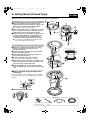
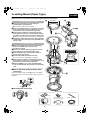
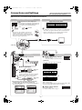
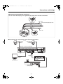
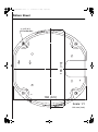
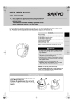
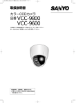
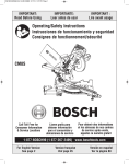
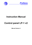
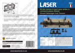
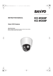
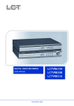
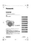
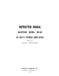
L5BU2_XE(INSTALLATION).book 0 ページ
2007年8月1日 水曜日 午前11時7分
INSTALLATION MANUAL
Color CCD Camera
Install these units securely according to this installation
manual. Be aware that allowing them to fall may cause
personal injury.
This installation should be made by a qualified service
person and should conform to all local codes.
Contents
Product Lineup . . . . . . . . . . . . . . . . . . . . . . . . . . . . . . . 1
Surface Mount . . . . . . . . . . . . . . . . . . . . . . . . . . . . . . . . 2
In-ceiling Mount (Closed Type) . . . . . . . . . . . . . . . . . . 3
In-ceiling Mount (Open Type) . . . . . . . . . . . . . . . . . . . . 4
Connections and Settings . . . . . . . . . . . . . . . . . . . . . . 5
Address Settings Table . . . . . . . . . . . . . . . . . . . . . . . . . 7
Pattern Sheet (inserted at the end of this manual)
Important
• Be careful when opening holes for installing the unit.
Work with the power and video cables pulled out for
easy installation.
• Make sure to properly perform waterproofing for the
ceiling where you are installing the unit.
• Make sure that the surface in the installation location
has no unevenness and is strong enough to bear the
total weight of the unit.
• Install this unit in an environment where the
temperature range stays between -10°C/+14°F and
+50°C/+122°F (no condensation allowed).
CAUTION: For VA-80S (Power Borard Unit)
ALL-POLE MAINS SWITCH with a contact separation of
at least 3mm in each pole shall be incorporated in the
electrical installation of the building.
Before Installing the Unit
Remove the plastic cover (A) and then the
tape (B) fixing the lens.
Put back the plastic cover (A), and turn it
clockwise until you hear it click to securely
lock it.
(A)
(B)
English
Please read this manual before installing and using this unit, and always follow the instructions in it for proper
use. Please also read the separate Instruction Manual before using the unit for proper use.
L5BU2_XE(INSTALLATION).book 1 ページ
2007年8月1日 水曜日 午前11時7分
Product Lineup
To install the camera unit, the optional housing is required. When using a housing, be sure to choose the correct
one for your environment of use.
Indoor Type
(Surface Mount)
(In-ceiling Mount)
+
☞P3
☞P4
Outdoor Type
☞P2
☞ Refer to the instruction
manual supplied with
each product.
☞ Refer to the instruction manual supplied
with each product.
Pole Mounting
Adapter (VA-80AP)
In-ceiling
Bracket
In-ceiling
Bracket
Closed Type
Open Type
VA-80ME
VA-80MF
Pendant Mounting
Bracket (VA-80BP)
Wall Mounting
Bracket (VA-80BW)
Attachment (VA-80A)
Power Board
Unit
(VA-84S;
for AC24V)
(VA-80S;
for AC230V)
Power Board
Unit
(VA-84S;
for AC24V)
(VA-80S;
for AC230V)
Power Board Unit
(VA-84S; for AC24V)
(VA-80S; for AC230V)
Surface Cover
VA-80F
–1–
Corner Mounting
Adapter (VA-80AC)
Outdoor Housing (VA-80EX)
Power Board Unit
(VA-84S; for AC24V)
(VA-80S; for AC230V)
● Clear Dome Cover (VA-CM8C)
● Smoked Dome Cover (VA-CM8S)
L5BU2_XE(INSTALLATION).book 2 ページ
2007年8月1日 水曜日 午前11時7分
Surface Mount
VA-80F
Make sure to also consult the Surface Cover Instruction Manual.
2
1. Installing the power board unit
1 Place the pattern sheet at the end of this manual on
1
A
the ceiling, mark the locations and drill the holes for
the cables and screws.
● Pull out the cables from the ceiling.
B
B
2 Attach the supplied dust sheet (A) to the base of the
power board unit and the detachable piece of the
sheet (B) to the side.
● Peel off the release-coated paper from the dust sheet
before attaching.
3 Pass the cables through the slit (C) in the dust
sheet.
4 Fix the power board unit to the ceiling using the
supplied screws (D) (4 places).
3
Surface routing (ceiling)
Pass the cables
through the cable hole
(E) at the side of the
power board unit, and
attach the dust sheet
(A) as shown in the
figure.
C
5
D
5 Connect the cables and set the switches.
☞ See “Connections and Settings” on page 5.
E
4D
A
G6
2. Mounting the camera unit
6 Fasten the camera unit safety wire (F) to the hook
(G) on the inner side of the power board unit.
7 Align the arrows (H) of the same color (blue) on the
camera unit and the power board unit, and push the
camera unit until they click.
F
8 Align the arrows (H) of the same color (blue) on the
H; Blue 7
inner side of the surface cover and the power board
unit, and fix the cover by rotating it clockwise.
■ How to attach the drop-prevention cable
(accessory)
1) Peel off the two-sided tape (K) at the end of the cable
and attach it to the hook (L) on the inner side of the
surface cover as shown in the figure.
2) Fasten the cable to the hook (M) on the side of the
power board unit.
H; Blue 8
M
K
Protrusion
Removed in case of
surface routing.
L
■ To remove the camera unit
Accessories
Dust sheet
–2–
Drop-prevention
cable
Screw (for power
board unit)
L5BU2_XE(INSTALLATION).book 3 ページ
2007年8月1日 水曜日 午前11時7分
In-ceiling Mount (Closed Type)
VA-80ME
Make sure to also consult the In-ceiling Bracket Closed Type Instruction Manual.
1
1. Installing the power board unit
φ192 mm/7.6”
1 Draw a circumference on the ceiling using the
B
A
supplied drop-prevention cable (A) as compass, and
drill a hole for installing the in-ceiling bracket.
● Pull out the cables from the ceiling.
B
2 Pass the supplied screws a and washer b through
each of the power board unit screw holes (B) and
fasten them loosely using washers (4 places).
2
B
a
B
3 C; Blue
b
3 Align the arrows (C) of the same color (blue) on the
power board unit and the in-ceiling bracket, and
mount the power board unit. Tighten firmly the
screws (B) loosely fastened in the previous step.
● Pass the video cable (D) through the bracket cable
hole as preparation for the next step.
D
5
2. Installing on the ceiling
4 Attach the supplied safety wire (E) to the ceiling
beam, for example, then connect it to the
bracket-top hook (F).
E
5 Connect the video cable and pass the connection
F
4
cables through the bracket.
E
4
F
6 Insert the bracket into the ceiling hole and fix it
using screws (G) (2 places).
7 Connect the cables and set the switches.
6
☞ See “Connections and Settings” on page 5.
G
G
8 Align the arrows (C) of the same color (blue) on the
G
6
camera unit and the inner side of the bracket, and
push the camera unit until they click.
7
9 Align the SANYO logos on the supplied bracket
cover and the bracket, and push the cover until they
click.
G
■ How to attach the drop-prevention cable
(accessory)
Fasten the drop-prevention cable (A) to the hooks (H) on
the bracket and its cover, then slide the cable as shown in
the figure.
C; Blue 8
H
A
9
H
■ To remove the camera unit
Accessories
Screw a, washer b
(for power board unit)
Drop-prevention
cable
–3–
Safety wire
Bracket cover
L5BU2_XE(INSTALLATION).book 4 ページ
2007年8月1日 水曜日 午前11時7分
In-ceiling Mount (Open Type)
VA-80MF
Make sure to also consult the In-ceiling Bracket Open Type Instruction Manual.
1
1. Installing the power board unit
2
φ196 mm/7.7”
a
1 Drill a hole (φ196 mm/7.7”) in the ceiling for
b
installing the in-ceiling bracket.
● Pull out the cables from the ceiling.
A
A
2 Pass the supplied screws a and washer b through
each of the power board unit screw holes (A) and
fasten them loosely using washers (4 places).
A
3 Align the blue sticker (B) on the bracket and the
3 B; Blue
arrow (B) of the same color on the power board unit,
and then mount the power board unit in the bracket.
● When inserting the power board unit, do it diagonally.
A
4 Mount the power board unit in the in-ceiling bracket.
7
Tighten firmly the screws (A) loosely fastened in the
previous step.
C
2. Installing on the ceiling
5 Attach the supplied safety wire (C) to the ceiling
5
beam, for example, then connect it to the
bracket-top hole (D).
D
6 Pass the connection cables through the slit in the
6
dust sheet (E), and connect the video cable.
E
7 Insert the bracket into the ceiling hole and fix it
5
using screws (F) (2 places).
C
D
8 Connect the cables and set the switches.
7
☞ See “Connections and Settings” on page 5.
9 Align the blue sticker (B) on the bracket and the
arrow (B) of the same color on the camera unit, and
then push the camera unit until they click.
8
À Align the SANYO logos on the supplied bracket
F
F
7
F
cover and the bracket, and push the cover until they
click.
■ How to attach the drop-prevention cable
(accessory)
B; Blue 9
Fasten the drop-prevention cable (G) to the hooks (H) on
the bracket and its cover, then slide the cable as shown in
the figure.
H
G
H
■ To remove the camera unit
Accessories
Dust sheet
–4–
Screw a, washer b
(for power board unit)
Drop-prevention cable
Safety wire
Bracket cover
L5BU2_XE(INSTALLATION).book 5 ページ
2007年8月1日 水曜日 午前11時7分
Connections and Settings
Do not connect the power cord until all other
connections have been completed.
Make sure to also consult the Power Board Unit Instruction Manual.
Power Supply Connection
G
N
Monitor Connection
For the connections use cables higher than
18 AWG.
☞ When using AC 24 V, follow the connection steps in
the leaflet titled “Connecting the power cable” that
comes with the power board unit (VA-84S).
L
<Live>
<Neutral>
<Ground>
Supported coaxial cables
Cable type
RG-59U (3C-2V)
RG-6U (5C-2V)
RG-11U (7C-2V)
Length
250 m (273.4 yd) max.
500 m (546.8 yd) max.
600 m (656.2 yd) max.
AC 230 V
• Using different cables from those specified here may attenuate the
video and/or sync signals and interfere with correct transmission.
• RG-59U coaxial cables can be used when distance between
devices is short, but not in duct or aerial routing.
A
• Fix the power cable end firmly so that the power
terminal connection does not come loose. Use
solderless terminals (ring or spade type) for wiring.
• After connection, always install the supplied power
terminal cover A for safety reasons.
BNC type
Joint board
2
1
Connections
SIDE-A
Switch Settings
1 System control setting switches
1 Controller connection
B
L
O
R
B
K
R
D
ON
• Switch 6 is unused.
• The factory setting is represented in bold.
WH S
B
R
LL
Y
G
R
LL
White
SIDE-B
1
3
4
5
6
1 234
1 Baud rate
Yellow
2
Set the same baud rate as that on the camera.
Switch
2400
4800
9600
19200
485A
485B
2 Alarm signal input
✱
IN 1 - 8
To COM
Set either to RS485 or coaxial (COAX).
Switch
Coaxial (COAX)
RS485
3 Alarm signal output
If a lamp is connected to this cable, it will light up
when an alarm signal is received or when the
built-in motion sensor detects movement.
Set the protocol for controlling the camera.
Switch
SSP (SANYO)
PELCO
Alarm output
signal
SET
SET
SET
SET
SET
SET
SET
SET
SET
PRESET
MENU
OFF
BACK
“OFF” is set by default.
When connecting multiple cameras, termination setting must be “ON”
on the last camera while it must be “OFF” on all others.
2 Address setting switches
ALARM
y
ALARM IN
ALARM OUT
ALARM DISABLE
1
1
OFF
MOTION
ALARM DISPLAY
OFF
OFF
PRESET
MENU
OFF
BACK
4
OFF
ON
4 Termination (Switch 5)
✱ All connection cables should be 24 AWG or higher with a
maximum length of no more than 600 m (656.2 yd).
☞ For details on 2 and 3, refer to the “Alarm Settings (ALARM)” in
the Instruction Manual.
CAMERA
LENS
PAN/TILT
AUTO MODE
ALARM
PRIVACY MASK
PASSWORD
LANGUAGE
OPTION
3
ON
OFF
3 Protocol
✱
To COM
2
OFF
OFF
ON
ON
2 Control method
Alarm input
signal
OUT 1/2
1
OFF
ON
OFF
ON
y
Set the camera address.
See “Address Settings Table” on page 7.
–5–
ON
1
2
3
4
5
6
7
8
L5BU2_XE(INSTALLATION).book 6 ページ
2007年8月1日 水曜日 午前11時7分
Connections and Settings
■ To prevent electromagnetic interference
Be sure to attach the clamping cores supplied with the camera unit to the cables as illustrated.
Power cable
Control and alarm input/output cables
Video cable
■ Connections for using coaxial control (System connection)
(1 - 16)
Video input
terminal
Video input
terminal
Camera
Camera
Digital video recorder (sold separately)
1
2
3
4
5
6
7
8
9
10
11
12
13
14
15
16
IN
OUT
MONITOR OUT
MON2
MAIN
A RS-485 B
DO NOT CONNECT TO PHONE LINE
Video input
terminal
Terminator
switch
Communication conversion
connectors
Monitor
(sold separately)
A TELEMETRY B
System controller
(sold separately)
–6–
VIDEO
L5BU2_XE(INSTALLATION).book 7 ページ
2007年8月1日 水曜日 午前11時7分
Address Settings Table
Addresses are specified by setting the switches to ON/OFF.
In the table, the circle mark “m” means ON. Set switches as shown in the table.
ON
PELCO protocol: 1 - 255
ON
SANYO protocol: 1 - 127
ON
3
4
5
6
7
8
1
2
3
4
5
6
7
8
OFF
2
OFF
1
Switch 8
• Address 1 - 127: OFF
• Address 128 - 255: ON
ON
• Switch 8 is unused.
Address
(Camera No.)
Protocol
SANYO/PELCO PELCO
0*
128
1
129
2
130
3
131
4
132
5
133
6
134
7
135
8
136
9
137
10
138
11
139
12
140
13
141
14
142
15
143
16
144
17
145
18
146
19
147
20
148
21
149
22
150
23
151
24
152
25
153
26
154
27
155
28
156
29
157
30
158
31
159
32
160
33
161
34
162
35
163
36
164
37
165
38
166
39
167
40
168
41
169
42
170
Switch No.
1 2 3 4 5 6 7
m
m
mm
m
m
mm
mmm
m
m
m
m m
mm m
mm
m mm
mmm
mmmm
m
m
m
m
m
mm
m
m m
m m m
mm m
mmm m
mm
m
mm
m mm
mm mm
mmm
m mmm
mmmm
mmmmm
m
m
m
mm
m
m
mm
mmm
m
m
m
m
m
m
m
m
m
m
m
m
m
m
m
m
m
Address
(Camera No.)
Protocol
SANYO/PELCO PELCO
43
171
44
172
45
173
46
174
47
175
48
176
49
177
50
178
51
179
52
180
53
181
54
182
55
183
56
184
57
185
58
186
59
187
60
188
61
189
62
190
63
191
64
192
65
193
66
194
67
195
68
196
69
197
70
198
71
199
72
200
73
201
74
202
75
203
76
204
77
205
78
206
79
207
80
208
81
209
82
210
83
211
84
212
85
213
Switch No.
1 2 3 4 5 6 7
mm
m
mm
m mm
mmm
mmmm
m
m
m
m
m
mm
m
mm
m
mm
mm
mm
m mm
m m mm
mm mm
mmm mm
mmm
m
mmm
m mmm
mm mmm
mmmm
m mmmm
mmmmm
mmmmmm
m
m
mm
m
m
mm
mmm
m
m
m
m m
mm m
mm
m mm
mmm
mmmm
m
m
m
mm
m
m
m
m
m
m
m
m
m
m
m
m
m
m
m
m
m
m
m
m
m
m
m
m
m
m
m
m
m
m
m
Address
(Camera No.)
Protocol
SANYO/PELCO PELCO
86
214
87
215
88
216
89
217
90
218
91
219
92
220
93
221
94
222
95
223
96
224
97
225
98
226
99
227
100
228
101
229
102
230
103
231
104
232
105
233
106
234
107
235
108
236
109
237
110
238
111
239
112
240
113
241
114
242
115
243
116
244
117
245
118
246
119
247
120
248
121
249
122
250
123
251
124
252
125
253
126
254
127
255
* When setting the address by using the menu screen on the camera, set the address setting switches to “0”.
–7–
Switch No.
1 2 3 4 5 6 7
mm
mmm
m
m
mm
m
mm
m mm
mm mm
mmm
m mmm
mmmm
mmmmm
m
m
m
m
m
m
m
m
m
m
mm
m
mm
m
mm
mm
mm
m
mm
m m
mm
mm
mm
mmm
mm
m mm
m
m mm
m m mm
mm m mm
mm mm
m mm mm
mmm mm
mmmm mm
mmm
m
mmm
m
mmm
mm
mmm
m mmm
m m mmm
mm mmm
mmm mmm
mmmm
m
mmmm
m mmmm
mm mmmm
mmmmm
m mmmmm
mmmmmm
mmmmmmm
L5BU2_XE(INSTALLATION).book 0 ページ
2007年8月1日 水曜日 午前11時7分
Pattern Sheet
186 (7.3)
4- φ4.5 (0.2)
P. D φ168 (6.6)
166 (6.5)
Scale: 1/1
Unit: mm (inch)
L5BU2_XE(INSTALLATION).book 1 ページ
2007年8月1日 水曜日 午前11時7分
L5BU2_XE(INSTALLATION).book 2 ページ
2007年8月1日 水曜日 午前11時7分
MEMO
...............................................................................................
...............................................................................................
...............................................................................................
...............................................................................................
...............................................................................................
...............................................................................................
...............................................................................................
...............................................................................................
...............................................................................................
...............................................................................................
...............................................................................................
...............................................................................................
...............................................................................................
...............................................................................................
...............................................................................................
L5BU2_XE(INSTALLATION).book 1 ページ
2007年8月1日 水曜日 午前11時7分
φ136 (5.4)
156 (6.1)
71 (2.8)
b Dimensions
Unit: mm (inch)
Printed on recycled paper
Imprimé sur du papier recyclé
Impreso en papel reciclado
Gedruckt auf Recyclingpapier
使用再生纸印刷
1AC6P1P3149-A
L5BU2/XE (0807KP-HS)
SANYO Electric Co., Ltd.
Printed in China