1
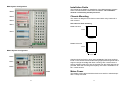
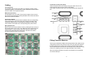
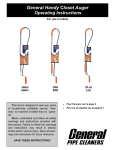
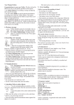
Multimessage Systems Limited
Home Communications Centre
Dealer’s stamp
Installation Guide
Multimessage Systems Ltd.
Unit 1 / 2, Block 26,
Cranborne Industrial Estate,
Cranborne Road, Potters Bar, Herts.
EN6 3JH
Tel. 01707 644480
Fax 01707 646745
www.multimessage.co.uk
Model
M400/s
ISSUE 1.1
Revised 06/09/05
8
1
2
7
M400 System Configuration
Installation Guide
M406
This booklet gives details for installation of the Multimessage Systems
Home Communications Centre M400 and M400s. The installation
must be carried out by trained personnel.
M402
Chassis Mounting
The chassis is designed to be flush mounted within a dry lined wall or
wall mounted.
M403
Hole sizes for flush mounting
M401
M400 Hole size
575mm
M404
470mm
M400/s Hole size
335mm
M400s System Configuration
470mm
M405
Chassis should be fixed in place using at least 4 of the fixing positions
found on the chassis back and sides using appropriate fixing methods to
support a weight of 15 Kg. With flush mounting care must be taken to
ensure sufficient cable entry into the chassis from the sides and rear are
provided. With wall mounting ensure plenty of access is available for cable / conduit access.
M401
M402
M406
6
Mains Power
The M400/s mains cable should be wired into a 240V AC switched spur
with a 3 Amp fuse fitted.
3
Cabling
TV Connections
Use satellite grade CT100 coax cable. The maximum length of each
connection should not exceed 50M. Industry standard TV aerial outlets
should be fitted in the required locations.
Network Connections
Use standard Cat 5 UTP cable. The maximum length of each connection should not exceed 50M. Industry standard Cat 5 sockets should be
fitted in the required locations.
Connection System
Each socket in the house should be numbered with the corresponding
numbered socket on the patch panel. Care needs to be taken when
routing the cables that the correct labels are applied to ensure each
room socket is connected to the corresponding patch panel socket.
Connections to the patch panel
Aerial connections are to be made by fixing the cable centre to the
screw terminal and the screen via the cable clamp.
Cat 5 cable connections are to be connected following the diagram below.
Brown/White
(8)
White/Brown
(7)
Green/White
(6)
Orange/White
(2)
White/Green
(3)
White/Orange
(1)
Wiring Patch Panel
Remove the room socket module covers by undoing the two screws on
the left hand side of the covers. The cables have to be fed through the
exposed panel. To gain access to the rear of the box undo the two
screws on the right hand side of this panel. Feed all of the cables
through the panel as shown in the picture.
Blue/White
(4)
White/Blue
(5)
Fitting Function Modules
The function modules are fitted to the left hand side of the chassis in the
configuration shown in the pictures on P6. First plug the power lead for
the first module into an empty power socket on the left of the chassis.
Then locate the tab of each into one of the slots in the centre rail. Finally
screw in the retaining screw on the right hand side of the module.
When all modules are fitted, the power to the M400/s can be switched
on via the fused spur.
4
5