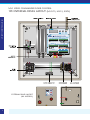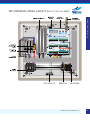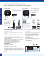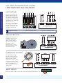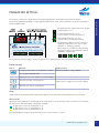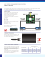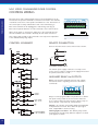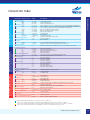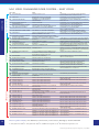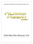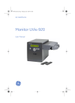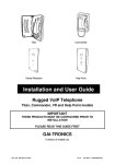
1
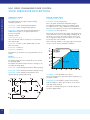
CONTENTS
2
INTRODUCTION
3
MODEL IDENTIFICATION
4
1PH INTERNAL PANEL LAYOUT
5
3PH INTERNAL PANEL LAYOUT
6
BASIC WIRING & INSTALLATION PROCEDURE
8
LIMIT SWITCHES AND ENCODERS
9
PARAMETER SETTING
10
SAFETY EDGES
11
PHOTOCELLS
12
CONTROL WIRING
13
PARAMETER TABLE
14
SOLID PARAMETERS
16
SLOW FLASHING PARAMETERS
18
FAST FLASHING PARAMETERS
20
FAULT CODES
issue 1
MS-1 SPEED COMMANDER DOOR CONTROL
INSTALLATION MANUAL
MS-1 SPEED COMMANDER DOOR CONTROL
INTRODUCTION
INTRODUCTION
Description
Safety Warnings
The Speed Commander control panel has
been specifically designed for high speed
doors and gates. The panel provides
inverter speed adjustment and control as
well as monitoring and responding to
external inputs.
• This control must only be installed by a qualified
person that has experience with automatic
doors/gates and knowledge of the relevant EU
regulations.
The Speed Commander has a
comprehensive range of parameters
which allow the door/gate manufacturer
and installer to obtain the optimum
performance. In addition fault diagnosis
is provided for the installer and end user
allowing the door or gate to be returned
to its optimum performance with the
minimum of delay.
Disclaimer
Whilst every effort has been made to
ensure that the details in this manual are
correct. Motion systems cannot be held
liable for damage or injury due to any
error or omission.
Who is this Instruction Manual for?
This manual is intended for installers and
door and gate manufacturers. It is not
intended for the end user. A separate
document should be supplied for the
end user.
• The installer has the responsibility for the CE marking
of the door/gate. The installer must inform / advise
the end user on how to use the door/gate.
• The Speed Commander is developed so it complies
with the requirements of EN 13241-1.
• All components used must be CE approved to enable
a final CE- marking of the complete installation.
• Safety edge must comply with EN 12978 and must
only be connected to the terminals prepared for this.
These inputs are of Safety Class II and are internally
supervised for the correct function before each
operation.
• The controller must be set up so that EN 12445 is
met. The control parameters must be locked before it
is handed over to the end user.
• The cable between the motor and control must be
shielded and connected as shown in this manual.
• Do not mount the controller in direct sunlight; this
might cause internal overheating of the controller.
• Do not make changes or modifications to the
controller.
• Do not work with the door or gate without
disconnecting the mains supply first.
• Terminals might contain high voltages up to
5 minutes after disconnecting the mains supply.
• The door/gate might start without warning therefore
a light or siren could be required.
• The control panel will not operate if the internal +24V
power supply is short-circuited. The display stays off.
2
The MS Speed Commander is extremely versatile in its application and therefore it is important that you can identify
which model you are working with and what parts of the manual are applicable.
When power is switched on, the control panel will show the model information i.e. power, program number and
software version. For example:
= Speed commander 1.5Kw, Program 15, Version 71
The Speed Commander has been pre-programmed to the value shown in the table when it was originally supplied to
reduce installation time.
Notes:
Serial Number
...........................................................
Software Version
...........................................................
Program Number
...........................................................
Date of Original Supply
...........................................................
MODEL IDENTIFICATION
MODEL IDENTIFICATION
Model type
MS 0.75, 230v, 1ph, 0.75kw (max 4.5 amp)
..........................................................................................
MS 1.5, 230v, 1ph, 1.5kw (max 7.0 amp)
..........................................................................................
MS 2.2, 400v, 3ph, 2.2kw (max 5.5 amp)
..........................................................................................
MS 4.0, 400v, 3ph, 4.0kw (max 9.0 amp)
..........................................................................................
Safety edge type. Selected by Parameter 7**
8K2 conductive edge (7** = 1)
..........................................................................................
Opto edge (7** = 2)
..........................................................................................
Other
..........................................................................................
Opto Interface relay required
Limit switch/encoder type. Selected by Parameter 8**
Incremental Encoder with reference switch (8** = 2)
..........................................................................................
Limit switches (8** = 5)
..........................................................................................
Incremental encoder with Mechanical stop
reference in the open direction (8** = 7)
..........................................................................................
Motion/AWG RS 485 Absolute resistor (8** = 9)
..........................................................................................
Incremental Encoder with reference switch
reference run in Dead Man (8** = 10)
..........................................................................................
Incremental encoder with Mechanical stop in
the close direction sliding gate operators
with a disengage lever (8** = 12)
..........................................................................................
Other
..........................................................................................
Notes:
www.motion-systems.co.uk
3
MS-1 SPEED COMMANDER DOOR CONTROL
1PH INTERNAL PANEL LAYOUT
1PH INTERNAL PANEL LAYOUT
EXTERNAL PANEL LAYOUT
(ALL MODELS)
4
(MS 0.75, MS1.5, 230V)
(MS 2.2, MS 4.0, 400V)
3PH INTERNAL PANEL LAYOUT
3PH INTERNAL PANEL LAYOUT
www.motion-systems.co.uk
5
MS-1 SPEED COMMANDER DOOR CONTROL
BASIC WIRING & INSTALLATION PROCEDURE
BASIC WIRING & INSTALLATION PROCEDURE
1PH POWER
3PH POWER
Connect a suitably rated 230V
L, N & E supply as shown.
Note: The Neutral terminal
is the same type as the brake.
A terminal driver is required
to open the clamp.
BRAKE
A 3mm terminal driver
is required to open the
cable clamp. Push the
screw driver in firmly
and insert the cable
before removing the
terminal driver.
Connect a suitably rated 400V
TPN & E supply as shown.
MOTOR
230V
3PH DELTA
400V
3PH STAR
Connect the motor to the
motor connector block on
the Speed Commander.
Note: A shielded cable must
be used. Connect the shield
to the earth connector.
INSTALLATION PROCEDURE
1. Mechanical Installation
5. Limit Switches
Ensure that the panel is mounted securely using the mounting
lugs provided.
2. Basic Power, Motor, Limit and Brake Connections
Where limit switches are used they should be set
when the control is in Dead Man Operation i.e.
J=1. The pre-close Limit switch should be set so
that it operates before the fully closed position,
but remains operated when the door/gate is
fully closed.
Connect the power supply, Motor, Motor Brake and limit/encoder.
6. Incremental Encoder
3. Switch on the Power
When using an incremental encoder, a reference
switch or position is required. The control uses
this as a fixed position from which to determine
the door/gate position.
Make the basic connections for Motor, Limits, Brake and Safety
circuit.
The display on the control panel will show the model information
i.e power,program number and program number.
For Example SCD 1.5 P15 U.0.71 which means a Speed
Commander 1.5Kw Program 15 version 71.
4. Motor direction
Set parameter J=1 (Dead Man)
Hold the step/store button in and at the same time use the up
and down buttons to move the door/gate.
Ensure that the door/gate will travel fully open and fully closed.
The torque boost (Parameter B) may need to be increased to ensure
the door/gate travels fully open and closed. If the motor travels in
the wrong direction reverse two of the motor connections. If an
error code EO2 appears then two of the encoder wires need to be
swapped.
6
Note: Quick step installation is only available on software versions 75 and above.
Step 1.
Move the door/gate to a mid travel position.
Step 2.
Select parameter J and use the up/down buttons to set the value to J=31.
Press Step/Store once to store this.
Use the up/down buttons to set J=5
Step 3.
Press Step/Store twice.
The display will show OPN. (Flashing)
Step 4.
Use the up/down buttons to open the door to the desired open position.
Step 5.
Press Step/Store to store the position.
BASIC WIRING & INSTALLATION PROCEDURE
7. 'Quick step' installation for Door/Gate Positions
The display will show CLO. (Flashing)
Step 6.
Use the up/down buttons to close the door to the desired closed position.
Step 7.
Press Step/Store to store the position.
Step 8.
The display will show REF (Flashing).
This step is not required for Absolute Resistor Limits.
Step 9.
Use the Membrane open button or another open input.
The door gate will run to its reference position.
The door/gate will now operate in full automatic mode.
Display changes to 000.
The door will run at the operational speed defined by the parameters. Additional control features can be added with
reference to the control inputs and outputs. When installation is complete set J=30 for end user operation.
Fine adjustment of the Door/gate positions
If minor adjustment of a position is required then this can be done by directly adjusting the parameter. It is not necessary
to carry out the installation procedure again. For example if you wish to make the door close further then unlock the
parameters, select parameter 0* and use the down button to set the value of the closed position. To increase the travel,
the up button should be used.
www.motion-systems.co.uk
7
MS-1 SPEED COMMANDER DOOR CONTROL
LIMIT SWITCHES AND ENCODERS
The Speed Commander will
function with limit switches.
The minimum requirement is
two switches although four is
preferable. If two switches are
used then they should be fully
open and pre-close.
The pre-close limit should be
set so that it operates before
the fully closed position, but
remains operated when the
door/gate is fully closed.
KEY
LIMIT SWITCHES AND ENCODERS
LIMIT SWITCHES
1 = Pre-open limit switch
2 = Open limit switch
3 = Open safety limit switch
4 = Close safety limit switch
ABSOLUTE RESISTOR
The absolute resistor uses
an RS485 connection from
the control. This system
retains its limit position in
the event of mains failure.
The Motion / AWG
absolute resistor is shown
here. Other systems can be
used with this control.
INCREMENTAL ENCODER
The incremental encoder
provides the best system for
speed control and position
accuracy. It uses a count
directly from the motor shaft.
A reference position or switch
is required. The control uses
this as a fixed point from
which to determine the door /
gate positions.
SHIELD
SAFETY CIRCUIT
Remove the link from X2.3 to X2.6 and connect the safety circuit from X2.3 to X5.
8
5 = Close limit switch
6 = Pre-close (reference) switch
PARAMETER SETTING
There are fifty parameters available to ensure optimum performance. Most of these parameters are pre-set and locked to
reduce installation time.
The parameters are separated into three groups:
Solid Parameters: 1 to J
Slow Flashing Parameters: 0* to J*
(1 asterix indicates a slow flashing parameter)
PARAMETER SETTING
The operation of the door is adjusted and controlled using parameters stored within the Speed Commander.
Fast Flashing Parameters: 0** to C**
(2 asterix indicates a fast flashing parameter)
The parameter number is shown in the green
display. It is important to note if it is a solid
parameter or a flashing parameter.
When the power is switched on after pressing
the step/store button, the parameters that are
displayed in sequence are:
As you press the Step/Store button the Green segment of the display changes, this is the parameter number.
Button Function
Button
Function
Display readout:
1. Step by step selection of the parameter number
Parameter number 1st digit / GREEN
2. Storing the displayed value
Parameter value: 3 digits / RED
Hold down for 3 sec to jump to the normal display
Increases the value of the parameter
Values with 4 or 5 digits scroll across the display
Decreases the value of the parameter
Faults
A fault can be cleared by pressing the up and down buttons at the same time and holding them in for 10 seconds.
Access Levels
Adjustment of the parameters is restricted by Access levels. Level 0 is for the end user, Levels 1 and 2 are for the installer.
The Access levels alter the number of parameters available.
To gain Access to Level 0, set parameter J= 30
To gain Access to Level 1, set parameter J= 31
To gain Access to Level 2, set parameter J= 32
Following installation the Access Level should be set to 0 for the end user ( i.e J=30).
www.motion-systems.co.uk
9
MS-1 SPEED COMMANDER DOOR CONTROL
SAFETY EDGES
SAFETY EDGES
It is essential that safety edges are used in conjunction with the Speed Commander. The safety edge should be suitable
for compliance with BSEN 12978. Only use the dedicated safety edge inputs on terminal X1.
OPTO EDGE
An Opto interface card is required when using
an Opto edge to provide category 2 safety.
Remove the 8K2 resistor from terminals X1.1
and X1.2 and connect as shown.
To test, check the DC voltages on the board or
in the panel:
X1.1
X3.1
X1.7
X1.2
=
=
=
=
0V
2.1V
11.6V
6.7V
The DC voltages of the Opto beams should be:
White/Green = 2.1V
White/Brown = 11.6V
Note - Parameter 7** must be set to the
value = 2 for Opto Edge.
Note - The resistor must be removed from X1.1/X1.2 when using
Opto Edge.
CONDUCTIVE EDGE
Remove the 8K2 resistor from terminals X1.1 and
X1.2 and replace with the two connectors from
the conductive edge connector.
CONNECTOR
8K2 EOL
RESISTOR
SAFETY EDGE FAULT FINDING
Due to the fact that safety edges are moving with
the door/gate, they often can be damaged. E08,
E09 and E10 are the safety edge faults. If the
safety edge is operated 3 times the door/gate will
remain open.
To check the safety edge, the diagnostic display
can be used ‘Set 0 ** = 3’. By checking the read
out, the faults may be diagnosed.
10
Safety Edge Type 7**
Readout Value
0
1
2
Edge activated
800
200
850
Normal range
537-384
537-384
725-600
200
800
200
Connection Fault
DOT PHOTOCELL
Mounting
Always mount the receiver (white cable) on the side
closest to the control panel. This provides the best noise
immunity.
Installation
If two sets of photocells are to be used connect and
install one set before starting the second set.
Switch off the supply to the control panel and connect
as shown below:
Mount the receiver on the side of the door closest to the
control panel.
Mount the transmitter at approximately the same height
on the opposite side of the door.
SAFETY EDGES
PHOTOCELLS
The exact position can be adjusted for the best
alignment using the control panel.
Alignment
Set the control panel to Deadman's operation J=1.
Set the display of the control panel (Parameter 0**) to
display the photocell.
Parameter 0**=10 for TR1, and 0**=11 for TR2 on Speed
Commander.
LINK REMOVED
X3.1 TO X3.4
Move the transmitter until the highest possible value can
be achieved.
The minimum value is 3 for the system to work.
Set 0** back to the original value and set J=4 for
Automatic operation.
Try to activate the photocells whilst the door is closing.
REFLECTIVE PHOTOCELL
LED
Mount the transmitter and align with the reflector so that the
LED on the top of the transmitter is illuminated.
Check that when the beam is broken that the contacts switch.
Remove the links from X4.9 and or X4.10 and connect the
black and white wires from X5 to X4.9 or X4.10 as required.
If either of the inputs X4.9 or X4.10 is not to be used it
should be connected back to X5.
TRANSMITTER
REFLECTOR
Photocell Disable (Dot and Reflective)
On some Door/gate installations the closing door/gate can break the photo cell when it is closing.
In order to overcome this problem the photocell can be disabled at this point. Move the door/gate
to the position where it should be disabled. Read the door position from the display. Then set
Parameter 9** to this value. The photo cell will be disabled when the door/gate passes this point in
the closing direction.
www.motion-systems.co.uk
11
MS-1 SPEED COMMANDER DOOR CONTROL
CONTROL WIRING
CONTROL WIRING
External controls and command inputs such as remote pushbuttons can be
connected to the Speed Commander. Connections are made to the six blocks
of terminals on the front of the Speed Commander X1 to X6. The function of
the control input is clearly marked above each of the terminals (Fig 1).
Each of the terminals can be unplugged to make wiring easier (Fig 2).
Each control input should have one side connected to the common rail X5.
Fig 1
Where ‘Stop’ inputs or ‘Stop/reverse’ inputs are to be connected then the
wire link should be removed and a ‘Normally Closed’ switch connected.
Note: Safety edges should not be connected to the stop/reverse inputs but
to the dedicated safety edge inputs.
CONTROL SCHEMATIC
Fig 2
REMOTE PUSHBUTTON
Remove the link from X5 to X2.7 and connect as shown.
POWER SUPPLIES
The 24v DC power supply is limited to 0.5 amps. Some
motion sensors require a separate power supply. This should
be specified at the time of order.
AUXILIARY RELAYS & OUTPUTS
Relays - The Speed Commander has four relay outputs
that can be used for signalling. These are connected to
terminal X6.
Relays 1 & 2 are programmable from parameters C* and D*.
The position relays switch at the end of travel when the
door or gate is within the relay tolerance. (All the relays on
X6 are rated at 1 amp 230v AC, 2 amp 30v DC).
Outputs - X3.9 and X3.10 are NPN outputs programmable
from parameters E* and F*. Note: When an opto edge is
used, output NPN-2 is used for testing.
Warning Lights & Sounders - The auxiliary relays can be
programmed to provide many different sequences. Contact
your supplier for details.
12
FAST FLASHING PARAMETER VALUES
I.E WHEN THE PARAMETER IS DISPLAYED
IT FLASHES QUICKLY DENOTED BY A **
SLOW FLASHING PARAMETER VALUES
I.E WHEN THE PARAMETER IS DISPLAYED
IT FLASHES SLOWLY DENOTED BY A *
SOLID PARAMETER VALUES
I.E WHEN THE PARAMETER IS DISPLAYED
IT DOES NOT FLASH
PARAMETER
DEFAULT VALUE
OPERATING SPEEDS
1
50HZ
2
35HZ
3
35HZ
TIMER VALUES 1,2 & 3
4
5 SEC
5
3 SEC
6
0
RAMPS
7
100HZ
8
50HZ
9
70HZ
MOTOR/POWER DATA
A
50HZ
B
10%
C
1350 RPM
D
2
POSITION/RELAY TOLERANCE
E
5
F
30
STOP RAMPS
G
100HZ
H
400HZ
OPERATING METHOD
J
1
DOOR/GATE POSITIONS
0*
0
1*
50
2*
500
3*
600
4*
700
TIMER 4 & RUN TIMER VALUES
5*
0
6*
16 SEC
TIMER FUNCTIONS
7*
1
8*
2
9*
4
A*
5
RELAY FUNCTIONS
B*
1
C*
1
D*
1
E*
1
F*
1
DEADMAN/INSTALLATION SPEED
G*
10HZ
DC BRAKING
10
H*
1 SEC
J*
DISPLAY READ OUT
0**
0
1**
0
MOTOR DATA
2**
0
2.500
3**
4**
10
OPERATIONS COUNTER
5**
0
SAFETY EDGE
6**
1
7**
1
LIMIT/ENCODER TYPE
8**
5
PHOTO CELL DISABLE POSITION
9**
0
CONTROL PANEL HEATING
A**
3
TORQUE LIMIT
B**
0
SERVICE COUNTER OPERATION VALUE
C**
0
RANGE
DESCRIPTION
0.5-150HZ
0.5-150HZ
0.5-150HZ
OPENING FREQUENCY HZ
CLOSING FREQUENCY HZ
FINAL CLOSING FREQUENCY HZ
0.0-999 SEC
0.0-999 SEC
0.0-999 SEC
VALUE OF TIMER 1, E.G. AUTO CLOSE TIMER 0=OFF, FUNCTION DETERMINED BY PARAMETER 7*
VALUE OF TIMER 2, E.G. AUTO CLOSE FROM PART OPEN 0=OFF, DETERMINED BY PARAMETER 8*
VALUE OF TIMER 3, TIMER 0=OFF FUNCTION DETERMINED BY PARAMETER 9*
0.1-400HZ/S
0.1-400HZ/S
0.1-400HZ/S
RAMP UP ACCELERATION DURING OPENING
RAMP UP ACCELERATION DURING CLOSING
RAMP DOWN DECELERATION
10.0-100HZ
1-100%
300-3000 RPM
1-1000
V/F RELATIONSHIP
TORQUE BOOST
MOTOR NOMINAL SPEED
NUMBER OF PULSES FROM THE ENCODER
1-999
1-999
POSITION TOLERANCE
RELAY TOLERANCE
1- 999HZ
1- 999HZ
‘SOFT STOP’ RAMP DOWN DECELERATION FOR PHOTOCELLS
‘EMERGENCY STOP’ RAMP DOWN DECELERATION FOR SAFETY EDGE
1-35
METHOD OF OPERATION J=1 DEADMAN, J=2 SET UP, J=3 AUTOMATIC, J=4 AUTOMATIC
+/- 32000
0 TO 32000
+/- 32000
+/- 32000
+/- 32000
FULLY CLOSED POSITION
SAFETY EDGE DISABLE POSITION
FINAL CLOSING FREQUENCY POSITION
PART OPEN POSITION
FULL OPEN POSITION
0.0-999 SEC
3.0-999 SEC
TIMER 4, VALUE, TIMER 0=OFF, DETERMINED BY PARAMETER A*
RUN TIMER, VALUE IN SECONDS, 16=16 SECONDS
1-7
1-7
1-7
1-7
FUNCTION
FUNCTION
FUNCTION
FUNCTION
OF
OF
OF
OF
TIMER
TIMER
TIMER
TIMER
1-16
1-16
1-16
1-16
1-16
FUNCTION
FUNCTION
FUNCTION
FUNCTION
FUNCTION
OF
OF
OF
OF
OF
BRAKE RELAY
RELAY 1
RELAY 2
NPN OUTPUT 1
NPN OUTPUT 2
0.5-25HZ
DEADMANS OPERATION FREQUENCY/SPEED
0-25%
1-100 SEC
DC BRAKE CURRENT
DC BRAKING TIME
PARAMETER TABLE
PARAMETER TABLE
1
2
3
4
0-13
DISPLAY READ OUT
0 OR FAULT CODE FAULT INDICATION
0 OR 1
2.0-8.0KHZ
0.5-10HZ
MOTOR DIRECTION
SWITCH FREQUENCY
MINIMUM FREQUENCY
0-32000 OPS
COUNTER 1 CYCLE=OPEN + CLOSE/FACTOR 10/INDICATOR 1.00=1000 CYCLES
1 OR 2
0-2
NUMBER OF SAFETYEDGES
SAFETY EDGE TYPE 2=OPTICAL EDGE, 1=N/O WITH 8K2
1-12
LIMIT TYPE, 5=LIMIT SWITCHES
-32000 TO 32000
PHOTO SENSOR DISABLE
0-50%
CONTROL HEATING
0-10
LIFTING FORCE LIMIT
0-32000
SERVICE COUNTER OPERATION OF RELAY
SHADED PARAMETERS ARE AVAILABLE TO ALL USERS ACCESS LEVEL 0. CODE J=30
ACCESS LEVEL 1, PERMITS ADJUSTMENT OF THE GREEN SHADED PARAMETERS AS WELL AS THOSE IN LEVEL 0. CODE J=31
ACCESS LEVEL 2, PERMITS ADJUSTMENT OF THE YELLOW SHADED PARAMETERS AS WELL AS THOSE IN LEVEL 0 & LEVEL 1. CODE J=32
ACCESS LEVEL 3, PERMITS ADJUSTMENT OF ALL PARAMETERS. CONTACT YOUR SUPPLIER FOR THE ACCESS CODE
www.motion-systems.co.uk
13
MS-1 SPEED COMMANDER DOOR CONTROL
SOLID PARAMETER DESCRIPTIONS
SOLID PARAMETER DESCRIPTIONS
OPERATING SPEEDS
Parameters 1,2 & 3
MOTOR/POWER DATA
Parameters A, B, C, & D
The speeds that the door/gate operates during
automatic operation.
Parameter A is the V/F.Set point.
Parameter 1 is the opening speed/frequency.
Parameter 2 is the closing speed/frequency.
Parameter 3 is the final closing speed/frequency to
enable the door/gate to creep to its final closed
position if required.
TIMER VALUES
Parameters 4,5 & 6
Set to the desired value in seconds. If 0 is set then the
timer will be OFF.
Parameter 4 is Timer 1 (The default value is for the
This is the point at which the Maximum voltage is
provided.The maximum voltage is the supply voltage.
For 50Hz motors A = 50,for 100Hz motors=100.Note
there are some exceptions to this for special applications.
Parameter B is the torque boost.
The Torque boost increases the voltage and therefore the
torque when the motor is accelerating or ramping up. If
the boost is to low the door/gate may not move, if it is
set too high there may be an over current error and the
boost may have to be reduced.
Due to the large number of door/gate types this must be
set by on site to suit the particular installation.
Auto-close timer).
Parameter 5 is Timer 2.
Parameter 6 is Timer 3.
The functions of the timers are set by parameters 7*, 8*
and 9*.
RAMPS
Parameters 7,8 & 9
The ramps change the rate at which the motor reaches
its operating speed.
The higher the value the faster the motor changes to its
intended operating speed.
Parameter 7 is the ramp up acceleration during opening.
Parameter 8 is the ramp up acceleration during closing.
Parameter 9 is the ramp down deceleration and
operates during opening and closing.
Parameter C is the Nominal motor speed.
This is the normal motor speed at its given frequency e.g
1350rpm at 50Hz.
Parameter D is the number of pulses from encoder.
Take the number of pulses per revolution of the motor
shaft and divide this by 4.
This value is normally factory set to suit the operator it
has been supplied with.
14
J=3 Automatic operation, with pneumatic safety edge
monitoring.
Parameter E is the position tolerance.
A safety check is made when a pneumatic safety edge is
used. The Speed commander expects a signal from the
safety edge between position 0* and 1*, when the
door/gate is closing.
This sets the tolerance within which the supply can be
switched off to the motor when it reaches its end of
travel positions. When the door/gate reaches its position
tolerance then the supply to the motor is removed and
the position relays, door/gate open and door/gate
closed are activated.
Example If the open position (Parameter 4*) is set at 700
and Parameter E is set to 5 then the supply to the motor
will be switched off when it reaches 695, and the door
open relay will operate.
Parameter F is the relay tolerance.
This sets the tolerance within which the door/gate
position relays remain activated.
Example If the open position (Parameter 4*) is set at 700
and Parameter E is set to 5 and F is set to 30 then the
door open relay will operate when it reaches 695, the
relay will de-energise when the door/gate closes and
passes the position 670.
STOP RAMPS
Parameters G & H
Parameter G is the 'Soft Stop' ramp.
If the door/gate is closing and the stop button is
activated it will stop quickly dependant on the value set
for G. This parameter should be set so the door stops
without excessive force on the drive mechanism.
Parameter H is the 'Emergency Stop' ramp.
If the door/gate is closing and the Safety edge is
activated it will stop quickly dependant on the value set
for H and then reverse. This parameter should be set so
the door/gate stops quickly to ensure that safe closing
force is not exceeded.
J=4 Automatic operation with optical/conductive safety
edge monitoring.
Before the start of every operation the safety inputs are
tested by an internal safety check that simulates an
activation of the safety edge. The processor must receive
this signal.
J=5 Quick Step installation operation
SOLID PARAMETER DESCRIPTIONS
POSITION/RELAY TOLERANCE
Parameters E&F
This enables the door positions to be set.
ACCESS LEVELS
Parameter J
See the parameter table for details of the access levels
for different parameters.
J=30
Access level 0. (End user level)
This is the end user Access level and allows the basic
operation and diagnostic parameters to be accessed.
J=31
Access level 1. (Installer level 1)
This is the first level for installers allowing the door to be
installed and some operating parameters to be adjusted.
J=32
Access level 2. (Installer level 2)
This is the second level for installers allowing the runtimer, safety edge type and limit/encoder type to be
adjusted.
When the installation is complete the parameters must
be locked to prevent adjustment by untrained users.
This is done by setting Parameter J=30.
OPERATING METHOD
Parameter J
Parameter J enables the operating method to be set
and the Access level for setting the parameters.
J=1 Dead mans operation.
The door/gate will operate under constant pressure, at
the deadmans speed (Set by Parameter G*).
J=2 Installation operation.
This enables the door positions to be set.
www.motion-systems.co.uk
15
MS-1 SPEED COMMANDER DOOR CONTROL
SLOW FLASHING PARAMETER DESCRIPTIONS
SLOW FLASHING PARAMETER DESCRIPTIONS
DOOR/GATE POSITIONS
Parameters 0*, 1* ,2* ,3* & 4*
By setting the timer functions to the appropriate value
then the correct function can be achieved.
Timer
Value
Starts
Function
1
When the door/gate
is fully open
Auto Close timer
2
When the door/gate
is at the part open position
Auto Close timer
3
When the door/gate
is fully open or part open
Auto Close timer
4
When the door/gate is fully
open or part open
Pre-warning timer
When the door/gate is
fully closed
Light Saving
When the door/gate is fully
open and after the Photocell
input x3.3 to x3.6 has been
activated. (Car wash/fire
station operation)
Auto Close timer
On power on. (The door/gate
runs to the reference position
after the time has elapsed)
Reference run
5
6
7
Parameter 0* is the fully closed position.
Parameter 1* is the safety edge disable position.
Set 50mm from the fully closed position.
Parameter 2* is the position where the door/gate
changes to its Slow down/creep speed.
Parameter 8* Sets the function of Timer 2.
Parameter 3* is the Part-open or pedestrian open
Parameter 9* Sets the function of Timer 3.
position.
Parameter A* Sets the function of Timer 4.
Parameter 4* is the fully open position.
When setting timers for relay functions please ensure
that only one timer is set for that function.
TIMER 4 AND THE RUN TIMER
Parameters 5* and 6*
Parameter 5* is Timer 4
RELAY FUNCTIONS
Parameters B*, C*, D*, E* and F*
Set to the desired value in seconds. If 0 is set then the
timer will be OFF.
The functions of the relays and NPN outputs that are
used in the speed commander.
The function of the timer 4 is set by parameters A*.
Parameter B*
Parameter 6* is the Run Timer
Sets the function of the Brake Relay.
This should be set to 5 seconds longer than the time
required to close the door/gate.
The Green dot on the 7 segment display is
illuminated when Brake Relay is active.
During a 'reference run' the a value of 3 times the
normal run time is used.
TIMER FUNCTIONS
Parameters 7*, 8*, 9* and A*
The functions of the timers that are used in the speed
commander.
16
Parameter 7* Sets the function of Timer 1.
Parameter C*
Sets the function of Relay RL-1.
The top left hand vertical segment is
illuminated when RL-1 is active.
Sets the function of Relay RL-2.
The top right hand vertical segment is
illuminated when RL-2 is active.
Parameter E*
Sets the function of NPN-1 output.
The bottom left hand segment is illuminated
when NPN-1 is active.
Parameter F*
10. Operates for a 0.5 pulse when the door/gate reaches
the closed position.
11. Operates after a reference run has been
completed, and the door/gate is operating in
automatic mode.
12. Flashes on/off during motion and during premovement if a timer function has been set for
pre-warning.
13. operates when the Service counter value has been
exceeded. The Service count value must be set in
parameter C**.
Sets the function of NPN-2 output.
14. Operates under inverter or door control error.
The bottom right hand segment is illuminated
when NPN-2 is active.
15. Operates when the internal temperature of the
Speed Commander exceeds 50 deg C, to operate an
additional fan.
The way in which the relay operates can be selected
from the details below.
Setting
1.
Operates when the frequency is above 0.
2.
Operates when the frequency is 0.
3.
Operates when the Auto close timer is inhibited e.g
if some one breaks a safety beam.
4.
Operates when the Auto close timer is inhibited for
more than 10 seconds.
5.
Operates when the the door/gate is open and the
Auto close timer is running.
6.
Not used
7.
Operates when the door is closed and static for light
saving. Note one of the auxiliary timers must be set
to light saving function i.e 5.
16. Operates during closing and during the premovement period if a timer function has been set
for pre-movement.
DEAD MAN/ INSTALLATION SPEED
Parameters G*
This parameter sets the speed that the door/gate
operates when it is operating under 'Deadmans'
operation or during a reference run.
DC BRAKING
Parameters H* and J*
DC braking is used to inject a DC current into the motor
windings when the actual door/gate position is inside
the position tolerance (Parameter E) at the end of travel,
i.e fully open or fully closed. This DC braking helps to
bring the door/gate to a stop before the motor brake
operates.
Example
Parameter H* sets the level of DC Brake current.
If C* (Relay RL1) is set to 7 (Light saving function).
Parameter J* sets the time for which the DC braking is
and Parameter A* (Timer 4) is set to 5 (Light saving
function).
active.
and 5* (Value of Timer 4) is set to 2.
Then relay RL1 will be energised when the door/gate is
opened and remain active until 2 seconds after it has
fully closed. This could be used to switch off a signal
light when the door/gate is closed and static,to save
energy.
8.
Operates during the Auto close time.
9.
Operates when the door/gate is moving and during
the pre-movement period if a timer function has
been set for pre-warning.
SLOW FLASHING PARAMETER DESCRIPTIONS
Parameter D*
For Freezer areas DC braking can be set to prevent the
drive from freezing up. Parameter J* should be set to
100 so that the motor receives a constant DC current.
Parameter H* should be selected to provide the correct
temperature.
www.motion-systems.co.uk
17
MS-1 SPEED COMMANDER DOOR CONTROL
FAST FLASHING PARAMETER DESCRIPTIONS
FAST FLASHING PARAMETER DESCRIPTIONS
DISPLAY READ OUT
Parameter 0**
DISPLAY READ OUT
Parameter 1** Fault log
The display can be changed to show different aspects of
the door/gate performance. By changing the value for
0** these different aspects can be shown.
Parameter 1** shows the last error code or activation e.g
(UU or OC3) is stored so that even after a mains failure
the fault cause is displayed.
Value / Function
0.
Door/gate position displayed in counter steps.
These values should increase when opening
and decrease when closing.
1.
Motor Current (amps)
2.
Intermediate circuit voltage
Displays the voltage present within the Speed
Commander. For 1PH the range is 292-357, for 3PH
the range is 509-622.
3.
Safety edge input 1 (Standard)
Assists with the diagnosis of safety edge faults.
The error log can be cleared by simultaneously pressing
the up and down whilst Parameter 1** is selected.
4.
Safety edge input 2 (Second input)
Assists with the diagnosis of safety edge faults.
MOTOR DATA
Parameter 2** Motor direction
5.
Reference switch input X1.6
Assists with the diagnosis of reference switch faults.
Only used with incremental encoders with a
monitored reference switch.
6.
Motor slip(Hz)
Shows the difference in Hz between the frequency
supplied by the inverter compared with that sent
back from the encoder. Note this only works with the
incremental encoders. This should be positive when
opening a rolling door and negative when closing.
Depending on the type of motor at certain switch
frequencies unpleasant noise from the motor may occur.
By changing the pulse frequency in the range from 2.0
to 5.0 kHz this noise can be reduced.
Motor slip(Rev/min)
Shows the difference in rpm between the frequency
supplied by the inverter compared with that sent
back from the encoder. Note this only works with
incremental encoders.
Parameter. 4** Minimum frequency
7.
8.
9.
Control Temperature/NTC value
This is a numerical representation of the temperature
of the inverter power section. The normal range is
from 420 to 210.
Lifting Force.
This is a numerical representation of the force used by
the drive, and can be used to set a lifting force restriction.
Parameter 3** Motor switch frequency
(Recommended value: 2.5 kHz).
Setting of the minimum speed during travel in the
“OPEN“ & “CLOSE” directions.
OPERATIONS COUNTER
Parameter 5** Operations counter
Display showing ? 10 = No of cycles
(1 cycle = open + close)
Example: Display showing: 1.234 = 12.340 Cycles
SAFETY EDGE
Parameter 6** Number of safety edges.
10. Photo sensor 1
This represents the strength of the signal of the thru
beam photo beams connected to inputs X3.1 to X3.4.
This is either 1 or 2.For High speed rolling doors it would
be normal just to have one edge. For sliding doors or
gates 2 edges may be required.
11. Photo sensor 2
This represents the strength of the signal of the thru
beam photo beams connected to inputs X3.3 to X3.6.
The display shows E10 if front edge is activated and E11
if rear edge is activated.
12. Actual frequency
This displays the actual speed of the motor whilst
running in hz.
13. Service counter
This displays the number of operations completed
by the door/gate. See also parameter 5**.
18
Changing the value from 0 to 1 or 1 to 0 changes the
direction of rotation like changing two motor phases.
Parameter 7** type of safety edge.
0.
(NC) Switch + 8K2 resistor - Terminal X1.2.
1.
(NO) Switch + 8K2 resistor - Terminal X1.2
(Conductive edge).
2.
Opto edge Fraba or Similar.
The Speed Commander is designed to function with three types of Limit switches or encoders.
- Limit Switches.
- Absolute resistor Limit (RS 485 Connection).
- Incremental Encoder with reference position.
Parameter 8** allows the Speed Commander to be set for the correct type of limit switch/Encoder.
Setting / Encoder type
Reference position/switch
Note
1 Incremental
N/C Switch in closed position
Resistors required to monitor the switch
2 Incremental
N/C Switch in closed position
Without resistors
3 Gfa/DES RS 485
Not required
4 Gfa/DES RS 485
Reverse count direction
Not required
5 Limit switches
Pre-close limit switch
Ideally 4 N/C switches required
6 Incremental
Photo beam input
T2- R 2 ( X3.3-X3.6)
The photo beam must be mounted in the open position
7 Incremental
Mechanical Stop in the
open position
8 Feig TST-PBA RS485
Not required
9 Motion/AWG RS 485
Not required
10 Incremental
N/C Switch in closed position
Reference run in Dead Man
11 Incremental
Photo beam input T2- R 2 ( X3.3-X3.6)
The photo beam must be mounted in the close position
12 Incremental
Mechanical Stop in the
open position
For use with disengage switch
Parameter 9** Photo cell disable position.
On some Door/gate installations the closing door/gate
can break the photo cell when it is closing. In order to
overcome this problem the photocell can be disabled at
this point. Move the door/gate to the position where it
should be disabled. Read the door position from the
display. Then set Parameter 9** to this value. The photo
cell will be disabled when the door/gate passes this
point in the closing direction.
Parameter A** Control Panel Heating
When the control panel is mounted in a freezer area, the
temperature in the control panel should be maintained
to prevent condensation. This can be done with this
parameter. The control panel will provide a small current
to the brake resistors which will heat them and the
panel. The heating will only switch on when the power
stage of the inverter is at 10 deg C and switched OFF
when the power stage is at 15 deg C. Because the
temperature is not directly shown in deg C, the
following chart can be used to compare the control
temperature or NTC value, its equivalent deg in C.
Temp (deg C)
NTC Value
0
10
15
40
50
70
570
470
420
210
160
85
FAST FLASHING PARAMETER DESCRIPTIONS
LIMIT/ENCODER TYPE
Parameter 8** Limit/Encoder type
The parameter A** is a percentage of time for which the
brake resistors will receive this current to heat them.
WARNING - This parameter must be adjusted with
caution, trying lower values for some time before
increasing them. The maximum values of 28 for 230v
1ph and 10 for 400v 3ph must not be exceeded.
Parameter B** Torque Limit
This parameter can only be used with incremental
encoders. With this feature it is possible to provide load
sensing in the opening direction to prevent a person
being lifted by a door. By setting the display 0** = 9 you
can display the lifting torque. If extra weight (eg 40Kg)
is added and the door is opened again, the new value
can be recorded. By selecting a value for B** between
the two values the torque limit is set.
WARNING - This feature should only be used following
consultation with Motion Systems and extensive testing
by the door manufacturer.
Parameter C** Service counter
A value can be entered here for the operations counter.
This must be used in conjunction with a relay function
13. E.g. A relay could be programmed to operate after
50,000 operations.
www.motion-systems.co.uk
19
MS-1 SPEED COMMANDER DOOR CONTROL - FAULT CODES
Frequency Inverter
FAULT CODES
CODE CAUSE
CHECK
TRY
UU
LOW VOLTAGE SUPPLY
THE MAINS VOLTAGE IS TOO LOW
OU
OVER VOLTAGE
OH
OVER HEATING INSIDE THE PANEL
EITHER,THE MAINS VOLTAGE IS TOO HIGH OR THE
DECELERATION IS TOO FAST,REDUCE PARAMETER 9.
THE INVERTER IS TOO HOT.CHECK VENTILATION.
CHECK PARAMETER J*=1.
THE DRIVE IS OVERLOADED
USE THE DISPLAY( 0**=2) TO SHOW THE VOLTAGE AT THE INVERTER.
FOR 230V THE VALUE IS 292-357 FOR 400V IT IS 509-622
USE THE DISPLAY( 0**=2) TO SHOW THE VOLTAGE AT THE INVERTER.
FOR 230V THE VALUE IS 292-357 FOR 400V IT IS 509-622
USE THE DISPLAY( 0**=8) TO SHOW THE TEMPERATURE OF THE POWER STAGE.
RANGE IS 420 TO 210
USE THE DISPLAY ( 0**=1) TO SHOW THE CURRENT. CHECK FOR MECHANICAL
DAMAGE OR OBSTRUCTION. CHECK THE DRIVE SELECTION.
USE THE DISPLAY( 0**=1) TO SHOW THE CURRENT. CHECK FOR MECHANICAL
DAMAGE OR OBSTRUCTION. CHECK THE DRIVE SELECTION.
USE THE DISPLAY( 0**=1) TO SHOW THE CURRENT.
REDUCE ACCELERATION PARAMETER 7
USE THE DISPLAY( 0**=1) TO SHOW THE CURRENT. REDUCE THE DC
BRAKING CURRENT AND CHECK THE RELAY TOLERANCE PARAMETER E
USE THE DISPLAY( 0**=1) TO SHOW THE CURRENT. CHECK FOR MECHANICAL
DAMAGE OR OBSTRUCTION. CHECK THE DRIVE SELECTION.
OC1 THE MOTOR CURRENT EXCEEDS THE
INVERTER RATING BY 210%
OC2 THE MOTOR CURRENT EXCEEDS THE INVERTER
OC3
RATING BY 150% FOR MORE THAN 30 SEC
OVER CURRENT WHILST ACCELERATING
THE INVERTER OR THE DRIVE ARE OVERLOADED.
CHECK FOR OBSTRUCTIONS, CHECK THE OPERATOR SELECTION.
THE ACCELERATION IS TOO FAST, REDUCE PARAMETER 7
OC4 OVER CURRENT WHILST DC BRAKING OPERATES
THE DC BRAKING IS TOO STRONG.REDUCE PARAMETER H*
OC5 SEVERE OVERLOAD
CHECK FOR A SHORT,OR THE MOTOR IS STALLED, BRAKE NOT
RELEASING,OR PARAMETER B IS SET TOO HIGH
THIS IS OK FOR A FEW SECONDS, BUT SHOULD NOT CONTINUE.
THE CURRENT IS HIGHER THAN THE RATED CURRENT OF THE INVERTER
THE CONNECTIONS TO THE PANEL AND FOR MECHANICAL
OBSTRUCTION.
THE MOTOR DIRECTION IS INCORRECT
THE CONNECTIONS TO THE PANEL AND FOR MECHANICAL
OBSTRUCTION.
THE POSITION OF THE REFERENCE POINT
50.5 DISPLAY FLASHES. THE CURRENT IS EXCEEDING
THE RATING OF THE INVERTER
E01 MECHANICAL OVERLOAD (SLIP MONITORING)
E02
E03
E04
OR MISSING SIGNAL FROM THE ENCODER
DIRECTION ERROR
NO SIGNAL FROM THE ENCODER (ONLY DURING INSTALLATION)
THE WRONG BUTTON HAS BEEN OPERATED
Door Control
E05 THE REFERENCE SWITCH IS SHORTED OR BROKEN
THE REFERENCE SWITCH
E06 THE REFERENCE SWITCH OPERATES IN THE
E07 RUN TIME EXCEEDED
IF USING AN INCREMENTAL ENCODER THE REFERENCE SWITCH
HAS OPERATED IN THE WRONG POSITION OR IF USING LIMIT
SWITCHES THE PRE-CLOSE LIMIT IS OPEN CIRCUIT.
CHECK THE SETTING OF PARAMETER 6*.
E08 THE SAFETY EDGE TEST HAS FAILED
E09 FAULT ON THE SAFETY EDGE
E10 THE SAFETY EDGE HAS OPERATED.
CHECK THE CONNECTIONS TO THE SAFETY EDGE.
CHECK THE CONNECTIONS TO THE SAFETY EDGE.
THE SAFETY EDGE HAS OPERATED
E11 THE 2ND SAFETY EDGE INPUT HAS OPERATED
THE SAFETY EDGE HAS OPERATED
E12 THE TORQUE LIMIT IS EXCEEDED
CHECK PARAMETER B**. THIS SHOULD BE =0.
E13 THE PARAMETERS ARE LOCKED
E14 COMMUNICATIONS ERROR WITH THE ABSOLUTE
ENTER THE CORRECT J CODE TO UNLOCK THE CONTROL.
CHECK THE WIRING TO THE ABSOLUTE RESISTOR LIMIT SWITCH.
WRONG POSITION
USE THE DISPLAY( 0**=0) TO SHOW THE POSITION. MOVE THE DOOR MANUALLY
AND ENSURE THAT THE POSITION VALUE HAS CHANGED IN THE DISPLAY.
SWAPPING THE GREEN AND YELLOW ENCODER WIRES.
USE THE DISPLAY( 0**=0) TO SHOW THE POSITION. MOVE THE DOOR MANUALLY
AND ENSURE THAT THE POSITION VALUE HAS CHANGED IN THE DISPLAY.
THIS ERROR CAN OCCUR DURING THE SET UP PROCEDURE. TRY TO START
TO RUN TO THE REFERENCE POSITION AGAIN.
THIS ERROR OCCURS IF 8**=1 I.E MONITORED REFERENCE SWITCH IS USED
AND THE SWITCH IS DAMAGED. USE THE DISPLAY(0**=5) THE VALUE SHOULD
BE 102-921
CHECKING THAT THE VALUE OF PARAMETER D IS CORRECT.
THE RUN TIMER SHOULD BE SET TO 3 SECOND LONGER THAN THE TIME
TAKEN TO CLOSE THE DOOR/GATE.
THIS CODE WILL WILL BE LATCHED AFTER 3 OPERATIONS. RESET BY
OPERATING IN DEADMAN OR SWITCHING OFF THE POWER.
THIS CODE WILL WILL BE LATCHED AFTER 3 OPERATIONS. RESET BY
OPERATING IN DEADMAN OR SWITCHING OFF THE POWER.
IF THE TORQUE LIMIT IS BEING USE CHECK FOR OBSTRUCTIONS WHILST
OPENING. OTHERWISE SET B**=0 TO TURN IT OFF.
LIMIT SWITCH
E15 ERROR DURING ‘QUICK STEP’ INSTALLATION.
E18 THE DISENGAGE LEVER ON THE OPERATOR
HAS BEEN ACTIVATED
J2.3 STOP INPUT CHECK IP X2.3
J2.4
J2.5
J2.6
J2.7
J3.4
OPEN INPUT CHECK IP X2.4
CLOSE INPUT CHECK IP X2.5
STOP INPUT CHECK IP X2.6
STOP INPUT CHECK IP X2.7
PHOTO CELL 1 INPUT CHECK X3.1 TO X3.4
J3.6 PHOTO CELL 2 INPUT CHECK IP X3.3 TO X3.6
Control Input
J4.1 STOP INPUT CHECK X4.1
J4.2 STOP INPUT CHECK X4.2
J4.3
J4.4
J4.5
J4.6
J4.7
J4.8
J4.9
OPEN INPUT CHECK X4.3
OPEN INPUT CHECK X4.4
CLOSE INPUT CHECK X4.5
PART OPEN CHECK X4.6
SPECIAL INPUT CHECK X4.7
GO INPUT CHECK X4.8
STOP/REV INPUT CHECK X4.9
J4.0 STOP/REV INPUT CHECK X4.10
J9.0 MEMBRANE OPEN BUTTON ACTIVE
J9.1 MEMBRANE STOP BUTTON
J9.2 MEMBRANE CLOSE BUTTON ACTIVE
20
TRY TO REPEAT THE QUICK STEP INSTALLATION.
THE POSITION OF THE DISENGAGE LEVER. THE SETTING
OF PARAMETER 8**
THE INPUT IS ACTIVE. CHECK THE INPUT DEVICE.
THE INPUT IS ACTIVE. CHECK THE INPUT DEVICE.
THE INPUT IS ACTIVE. CHECK THE INPUT DEVICE.
THE INPUT IS ACTIVE. CHECK THE INPUT DEVICE.
THAT EITHER THERE IS A LINK FROM X3.1 TO X3.4 OR THAT THE
PHOTOCELL IS CLEAR.
THAT EITHER THERE IS A LINK FROM X3.3 TO X3.6 OR THAT THE
PHOTOCELL IS CLEAR.
THE PANEL MTD STOP BUTTON IS ACTIVATED
THE NEUTRAL PROTECTION RELAY IS OPERATED ON 3PH UNITS.
I.E NO NEUTRAL FROM THE MAINS
THE LOOP INPUT IS ACTIVE
THE INPUT IS ACTIVE.CHECK THE INPUT DEVICE.
THE INPUT IS ACTIVE.CHECK THE INPUT DEVICE.
THE INPUT IS ACTIVE.CHECK THE INPUT DEVICE.
THE INPUT IS ACTIVE.CHECK THE INPUT DEVICE.
THE INPUT IS ACTIVE.CHECK THE INPUT DEVICE.
THE ALIGNMENT FOR THE PHOTO CELLS
CLEARS CHECK THE SWITCH.
THE ALIGNMENT FOR THE PHOTO CELLS
REMOVING THE INPUT WIRE AND FITTING A LINK TO X5. IF THE FAULT
CLEARS CHECK THE SWITCH.
REMOVING THE INPUT WIRE.IF THE FAULT CLEARS CHECK THE SWITCH .
REMOVING THE INPUT WIRE AND FITTING A LINK TO X5.IF THE FAULT
CLEARS CHECK THE SWITCH.
CHECK THAT THERE IS NOT A SHORT ON THE 12V SUPPLY X1.7.
CHECK THE MAINS SUPPLY THAT THE NEUTRAL IS PRESENT. FOR 230V
PANELS CHECK THE INPUT
REMOVING THE INPUT WIRE.IF THE FAULT CLEARS CHECK THE SWITCH.
REMOVING THE INPUT WIRE.IF THE FAULT CLEARS CHECK THE SWITCH.
REMOVING THE INPUT WIRE.IF THE FAULT CLEARS CHECK THE SWITCH.
REMOVING THE INPUT WIRE.IF THE FAULT CLEARS CHECK THE SWITCH.
REMOVING THE INPUT WIRE AND FITTING A LINK TO X5.IF THE FAULT
REMOVING THE INPUT WIRE AND FITTING A LINK TO X5.IF THE FAULT
CLEARS CHECK THE SWITCH.
DOES THE FAULT CLEAR WHEN YOU REMOVE YOUR FINGER FROM THE
TRY TO CHECK THE CONNECTIONS TO THE MEMBRANE PUSHBUTTON.
MEMBRANE. IF NOT CHECK AND OR REPLACE THE MEMBRANE BUTTON. THIS MAY BE DAMAGED.
DOES THE FAULT CLEAR WHEN YOU REMOVE YOUR FINGER FROM THE
TRY TO CHECK THE CONNECTIONS TO THE MEMBRANE PUSHBUTTON.
MEMBRANE.IF NOT CHECK AND OR REPLACE THE MEMBRANE BUTTON. THIS MAY BE DAMAGED.
DOES THE FAULT CLEAR WHEN YOU REMOVE YOUR FINGER FROM THE
TRY TO CHECK THE CONNECTIONS TO THE MEMBRANE PUSHBUTTON.
MEMBRANE.IF NOT CHECK AND OR REPLACE THE MEMBRANE BUTTON. THIS MAY BE DAMAGED.
Motion Systems Limited, Lower Hall Farm, Common Lane, Lower Stretton, Warrington, Cheshire WA4 4PE
T: +44 (0)870 600 0986 | F: +44 (0)870 600 0987 | E: [email protected] | W: www.motion-systems.co.uk
Brochure Designed & Produced by Division Design Ltd / 01606 888252