1
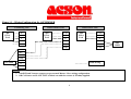
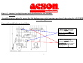
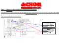
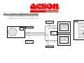
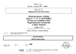
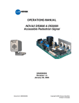
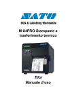
Multisplit Installation Manual
Model Reference:
A5CM2020ER
Model Reference – A5CM2020ER
Equipment - 2 off A5CM20ER matched with 1 off A5LC40CR
Configuration – Master / Slave Twinsplit
a) Mains Power
• Separate Power supplies are required to indoor and outdoor units.
• Power to each indoor unit should be 240v 1ph with a 5amp motor rated fuse
supply.
• Power to outdoor unit should be 420v 3ph with a 25amp per phase fuse
supply.
b) Interconnecting and Control Cables
• From Outdoor Unit to Indoor Master Unit = 3 Core
• Master Unit to Slave Unit control using 2 off Nim Boards and One off
Netware Controller.
• Slave Unit Outdoor Fan Sensor connection on PCB fitted with resistor.
c) Wiring Configuration
•
See Figure 1.1 on the following pages.
Connecting the Nim Controller and Boards.
MASTER UNIT
1. Plug the cable supplied with the Nim board into CN1 on the Nim and connect it to
CN4 on the master unit indoor pcb
2. Plug the Netware controller cable into CN2 on the Master Unit Nim board and
match the coloured wires to the corresponding coloured connections on the inside
back of the Netware controller.
Address the Master unit using the dip switches as follows:
3. Dip Switch marked DSW1 (eight switches)
LEAVE ALL SWITCHES DOWN (OFF)
4. Dip Switch Marked DSW2 (four switches)
LEAVE ALL SWITCHES DOWN (OFF)
This unit is now addressed as the master unit.
SLAVE UNIT
5. Plug the cable supplied with the Nim board into CN1 on the Nim and connect it to
CN4 on the slave unit indoor pcb
Address the Slave unit as follows:
6. Dip Switch marked DSW1 (eight switches)
LEAVE ALL SWITCHES DOWN (OFF)
7. Dip Switch marked DSW2 (four switches)
LEAVE SWITCH 1 / 2 / 3 SET DOWN (OFF)
MOVE SWITCH 4 UP (ON)
This unit is now addressed as the slave unit number 1
Connect the Nim Boards together as follows:
8. Connect a two core cable of about .75mm to CN3 on the Master unit Nim
board (connector is on top right of board) and note which cable plugs in to A
and which in to B as the connection has polarity.
9. Run the cable to the Slave unit Nim board and connect it in the same way.
MAKE SURE THAT THE CABLES ARE IN THE SAME CONNECTIONS
AS IN THE MASTER UNIT NIM BOARD.
The Nim Boards connection is now complete. Once power is applied the Master
unit will be controlled by the Netware controller and the Slave unit will copy the
function of the Master unit.
Figure 1.1 – Wiring Configuration for A5CM2020ER
Condensing Unit
R
3ph
Power
Feed
S
T
Indoor Slave Unit
Indoor Master Unit
1ph
Power
Feed
L/ L1
L/ L1
1ph
Power
Feed
N/L2
E
N/L2
E
N
4WV
4WV
E
OF
OF
Comp
Comp
A
4 WV
OF
Comp
NOT USED
L
Field Wiring
N
E
NOTES:
1. Nim PCB and Netware setup are as per normal Master / Slave wiring configuration.
2. OD Coil Sensor on SLAVE UNIT is linked out with the resistor (4.7Kohm) supplied.
4
NOT
USED
Figure 1.2 – Outdoor Unit High Pressure Switch Modification for A5CM2020ER.
(FOR UNITS WITHOUT PHASE PROTECTION BOARD)
A modification is required to ensure that the high pressure switch remains operational when using the A5LC40CR in a
multisplit application.
Carry out the modification on site as follows:
1. Remove Blue Wire from
contactor at point A2 and
Mains Neutral Terminal
and discard.
2. Remove Black High
Pressure Switch Wire from
Terminal A and re-connect
directly to point A2 on the
contactor.
5
Figure 1.3 – Outdoor Unit High Pressure Switch Modification for A5CM2020ER
(FOR UNITS FITTED WITH PHASE PROTECTION BOARD)
A modification is required to ensure that the high pressure switch remains operational when using the A5LC40CR in a
multisplit application.
Carry out the modification on site as follows:
1. Remove Blue Wire from
contactor at point A2 and
Mains Neutral Terminal
and discard.
2. Remove Black High
Pressure Switch Wire from
Terminal A and re-connect
directly to point A2 on the
contactor.
6
Figure 1.4 - Pipework Configuration for A5CM2020ER
•
•
Pipe sizes for the A5CM20ER are 1/4” Liquid & 1/2” Gas
Pipe Sizes for the A5LC40CR are 3/8” Liquid & 5/8” Gas
NOTES:
1/2” Gas
C/U
1.
A5CM20ER
Cassette
Master Unit
5/8” Gas
2.
1/4”
Liquid
A5CM20ER
Cassette
Slave Unit
3/8” Liquid
1/2” Gas
7
A reducing Tee is
necessary where
pipework is split
between each
cassette on BOTH
Liquid and Gas
Lines.
The distance from
the tee to each
indoor unit MUST
be more or less
equal to prevent
liquid flooding one
of the cassettes and
starving the other.