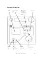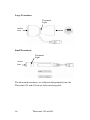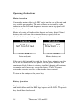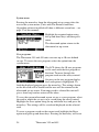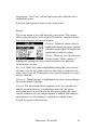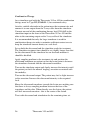
1
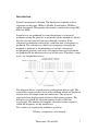
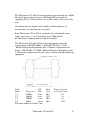
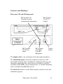
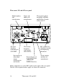
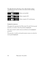
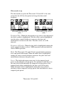
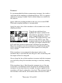
E M S P h ys i o L td .
Grove Technology Park
Downsview Road
Wantage
Oxfordshire OX12 9FE
England
User Manual
THERASONIC 355 & 455
Models 98 & 99
2
Therasonic 355 and 455
General Information
This manual provides the necessary information for the installation
and operation of the Therasonic 355 and 455 Units. These
instructions must be studied before putting the unit into operation.
The information contained in this manual is subject to change
without notice.
No part of this manual may be photocopied, reproduced or translated
into another language without the prior written consent of EMS
Physio Ltd.
The Therasonic 355 and 455 units are single and dual frequency
ultrasound therapy units. Both units may be mains only or
mains/battery powered.
Therapeutic ultrasound has been applied to a wide range of
conditions with successful outcomes. These include acute and
subacute traumatic and inflammatory conditions, chronic rheumatoid
and arthritic conditions, scar and excessive fibrous tissue and for
pain relief.
It is intended that the Therasonic 355 and 455 units are only used by
qualified healthcare professionals such as physiotherapists who have
received training in electrotherapy.
Record of Amendments
ISSUE
1
2
3
4
5
6
7
8
COMMENTS
Initial Issue
Revised
Revised
Revised
Revised
EMC Tables added
Protocols and Dose Algorithm added
Revised
Therasonic 355 and 455
DATE
27/02/2003
04/11/2003
09/02/2005
22/06/2006
01/10/2007
31/01/2008
31/03/2008
28/09/2010
3
EC Declaration of Conformity
EMS Physio Ltd
Grove Technology Park
Downsview Road
Wantage
Oxfordshire
OX12 9FE
United Kingdom
Declares that the following medical device is in
conformity with the essential requirements and
provisions of Council Directive 93/42/EEC and is
subject to the procedure set out in Annex 2 of Directive
93/42/EEC under the supervision of Notified Body
Number 0120, SGS United Kingdom Ltd.
Product Name
Therasonic 355 & 455
Model Numbers
99 & 98
Signature
4
Position
Technical Director
Date first issued
27th February 2003
Therasonic 355 and 455
Contents
page
1
Title
General Information
3
Record of Amendments
3
Declaration of Conformity to 93/42/EEC
4
Contents
5
Warranty
6
Introduction
7
Contraindications
9
Technical Specification
10
Controls and Markings
13
Installation
17
Operating Instructions
18
Protocols
27
Dose Algorithm
28
Maintenance
30
EMC Tables
31
Therasonic 355 and 455
5
Warranty
This EMS Physio Ltd., (hereinafter called the company) product is
warranted against defects in materials and workmanship for a period
of two years from the date of shipment. The Company will at its
option, repair or replace components which prove to be defective
during the warranty period, provided that the repairs or replacements
are carried out by the Company or its approved agents.
The Company will consider itself responsible for the effects on
safety, reliability and performance of the product:only if assembly operations, re-adjustments, modifications or
repairs are carried out by persons authorised by it,
only if the product is used in accordance with the instructions
for use,
only if the electrical installation of the relevant room complies
with the appropriate national requirements.
Should the product be returned to the Company for repair it must be
sent carriage paid.
Consumable items, for example, electrodes, electrode covers and
batteries, are excluded from the above warranty.
6
Therasonic 355 and 455
Introduction
Sound is mechanical vibration. The human ear responds to these
vibrations in the range 20 Hz to 20 kHz. Sound above 20 kHz is
called ultrasound. Therapeutic ultrasound is sound in the range 500
kHz to 5 MHz.
Sound waves are produced by some disturbance in a material
medium causing the particles or molecules of the medium to vibrate.
For this reason sound will not pass through a vacuum. If the
vibration is continuous and regular a constant tone or frequency is
produced. The vibration or sound wave propagates through the
medium as particles in the medium pass on their vibration to
neighbouring particles and series of compressions and rarefactions
are produced in the direction of travel of the wave. Therefore, sound
waves are longitudinal waves.
The diagram shows a sound wave travelling from left to right. The
vertical bars represent thin slices of the medium which are displaced
to form areas of compression and rarefaction. The sinewave
represents their displacement relative to their mean position. The
distance over which the vibration repeats itself is called the
wavelength. The number of complete vibrations in one second is
called the frequency of the sound wave.
The velocity of sound in the medium is given by:
Velocity = frequency x wavelength
Therasonic 355 and 455
7
Sound will travel faster through media where the molecules are
closer together and so the velocity is higher in solids than in liquids,
and higher in liquids than in gasses. For example, the velocity of
sound in stainless steel is approximately 5800 m/s, in water 1500 m/s
and in air only 330 m/s.
As the sound wave passes through the medium, causing molecules to
vibrate, some of the energy in the wave is converted from kinetic
energy to heat. For a collimated sonic beam the intensity, power per
unit area, therefore, decreases exponentially with the distance
travelled.
The attenuation of the beam is also dependent upon the frequency of
the sound. In solids the attenuation is proportional to frequency
whereas in liquids the attenuation is proportional to the square of the
frequency. The usual method of specifying the degree of attenuation
of ultrasound in different media is by the half depth. The half depth
is the distance the ultrasound must travel through the medium for its
intensity to be reduced to one half of its original value. Many
attempts have been made to measure the attenuation in various types
of tissue with varying results. It is perhaps more important to
remember which types of tissue have the highest absorption and
which the lowest. With the lowest absorption first the order is, fat,
muscle, skin, tendon, cartilage and bone. For soft tissue the half
depth is around 50 mm at 1 MHz and 15 mm at 3 MHz.
It is also important to remember that where there is a change in
medium or tissue type there will be both reflection and refraction of
the ultrasound beam. In particular, there is almost 100% reflection at
the interface of a solid or liquid to air at therapeutic ultrasound
frequencies. Any air bubbles in coupling medium will therefore
reduce the effective intensity of the ultrasound. Also bone reflects a
high percentage of incident ultrasound. It is important, therefore,
when applying ultrasound to keep the transducer orthogonal to the
surface of the treatment area, to keep the ultrasound transducer
moving and to use a good coupling medium to avoid unwanted
reflections and locally high intensities.
8
Therasonic 355 and 455
Contraindications
Tumours, as ultrasound affects tissue repair and could therefore
encourage growth
Infections, due to the risk of spreading the infection
Pregnancy, treatment over the pregnant uterus as ultrasound could
affect rapidly dividing cells
Radiotherapy, sites that have received radiotherapy treatment during
the last six months
Thrombosis and impaired circulation.
Areas of impaired sensation
Haemorrhage, due to the risk of increased bleeding, including
recently controlled bleeding and haematoma.
Haemophilia
Implanted devices such as cardiac pacemakers should be avoided
due to the possibility of affecting their operation. Also some plastics
used in replacement surgery may be affected by absorption of
ultrasound energy. Metal implants may lead to reflections, and as a
precaution low doses of ultrasound should be used near these.
Extreme care should be taken when treating areas near the eye
because of the danger of damage to the retina.
Similarly, extreme care should be taken near the ears and
reproductive organs
Therasonic 355 and 455
9
Technical Specification
General
Power Input
Battery (optional)
Classification (EN60601-1)
Mains Fuses
Size (height x width x depth)
Weight
Treatment Programs
Protocols (optional)
Dose Algorithm (optional)
Ultrasound
Frequency
Maximum Intensity
Maximum Output Power
Output Modes
Pulse Duration
Treatment Timer
Contact Monitor
100-240 Vac 50/60 Hz
Internal Rechargeable (NiMh)
Class 1, Type BF
2 x T630 mA (5 x 20 mm)
100 x 240 x 210 mm
2.2 kg (excluding battery)
10 user-defined set-ups
14 treatments
Calculates treatment settings from
entered parameters.
1.1 MHz ±5% and 3.4 MHz ±5%
1.5 W/cm2 in CW
3.0 W/cm2 in pulsed modes
6 W average (Mains operation only)
CW and pulsed 1:1, 1:2, 1:4 and 1:9
2 ms
0 to 30 minutes* (treatment linked)
Light on transducer
Large Ultrasound Transducer
ERA
4 cm2
BNR
<5
Beam Type
Collimated
Small Ultrasound Transducer
ERA
BNR
Beam Type
1MHz
0.6 cm2
<5
Divergent
3MHz
0.4 cm2
<5
Collimated
Transducers for use with the Therasonic 355 and 455 are fully
interchangeable and suitable for underwater treatment (IPx7 rated).
*
Prior to firmware version 1.12, the maximum treatment time was 20 minutes
10
Therasonic 355 and 455
The Therasonic 355 and 455 are designed to operate from any 50/60
Hz single phase supply between 100 and 240 Vac capable of
supplying 50 VA. Connection is via an IEC socket at the rear of the
unit.
All information on model, serial number, and month/year of
manufacture is located on the rear panel.
Each Therasonic 355 or 455 is supplied with a detachable mains
cable, spare fuses, a 4 cm2 treatment head, 180ml bottle
of Therasonic coupling medium and this manual.
The Therasonic 355 and 455 have been designed to meet the
requirements of BS EN 60601-1:1990 (BS5724:Part 1:1989)
"Medical Electrical Equipment, Part 1:General requirements for
Safety", BS EN 601-2-5:2000 "Medical Electrical Equipment, Part
2.5 Particular requirements for the safety of ultrasonic physiotherapy
equipment"
Pulse
Off
Mode
Frequency Time
1:1
250 Hz
2 ms
1:2
166 Hz
4 ms
1:4
100 Hz
8 ms
1:9
50 Hz
18 ms
The pulse width is fixed at 2 ms
Duty
Cycle
50%
33%
20%
10%
Therasonic 355 and 455
Temporal peak
to average ratio
2:1
3:1
5:1
10:1
11
Environmental Conditions for Transport and Storage
Temperature
-10 to +35 C
Relative Humidity
5 to 95%
Atmospheric Pressure
500 to 1060 hPa
Output Display
The Therasonic 355 and 455 display shows the temporal-peak
spatial-average ultrasound intensity and optionally the temporalaverage power or the temporal-peak power as selected
Accessories
Catalogue
Number
SLA9120
SLA9130
SLA9150
SLA9160
EMS502
EMS502A
EMS502B
EMS525
EMS157
EDC320
Description
Large Dual-frequency Transducer
Small Dual-frequency Transducer
Large Angled Dual-frequency Transducer
Combination Therapy Lead
EMS Coupling Medium (12 x 170ml bottles)
EMS Coupling Medium 1litre bottle
Dispenser Pump for 1 litre bottles
SoLo Shoulder Bag
SoLo Treatment Trolley
Protocol and Dose Algorithm Software
Supplied with each unit is a detachable mains lead complete suitable
for the country to which it is delivered. Replacement or additional
mains leads are shown below.
EMS Part Number
6-85
6-112
6-119
Description
UK mains lead
European mains lead
North America mains lead
For other countries contact EMS Physio Ltd. or the agent from
whom the unit was purchased.
12
Therasonic 355 and 455
Controls and Markings
Therasonic 355 and 455 front panel
IEC Symbol 348
Attention, consult
accompanying documents
IEC Symbol
878-01-36
Input
IEC Symbol
878-02-03
Type BF
Equipment
IEC Symbol
878-01-37
Output
Output
Socket
The output socket is for connection of the ultrasound transducer
The stimulation input is internally connected to the face of the
ultrasound transducer and is intended for combination therapy. Any
stimulator connected to the socket must be classified as type BF
according to EN 60601-1 for continued safety. A suitable connecting
lead is available from EMS Physio Ltd.
The infrared window is for the IrDA interface used for service and
calibration purposes.
Therasonic 355 and 455
13
Therasonic 355 and 455 rear panel
Model number
and
classification
CE mark
showing
conformity to
93/42/EEC
Description of
ultrasound
output
waveform for
each mode
Name and
address of
manufacturer
Ultrasound symbol
according to Health
and Welfare Canada
safety code 23
Ultrasound
frequency,
rated output
and intensity
Do not dispose of
as unsorted waste
(2006/96/EC
WEEE Directive)
IEC symbol 348
Attention, consult
accompanying
documents
Serial number
and date of
manufacture
Mains connection is via the IEC socket on the right of the rear panel.
Details of the required mains supply are above the connector.
14
Therasonic 355 and 455
Therasonic 355 and 455 top
LCD
up and down
keys
Power
key
IEC
Symbol
848-01-05
Stand-by
IEC Symbol
848-01-26
variability in
steps
Power
indicator
Therasonic 355 and 455
menu key
Control knob
15
Large Transducer
Treatment
Light
Active
face
Small Transducer
Treatment
Light
Active
face
The ultrasound transducers are calibrated independently from the
Therasonic 355 and 455 and are fully interchangeable.
16
Therasonic 355 and 455
Installation
Upon receipt, check for any visible damage which may have
occurred in transit. If any signs of damage are found then retain all
packing material and inform the carrier and the Company or its agent
from whom the unit was purchased.
If not already fitted, connect a suitable plug to the mains cable. The
plug must have provision for an EARTH (GROUND) connection.
The mains cable has the following colour code: BROWN is LIVE
(LINE), BLUE is NEUTRAL and GREEN/YELLOW is EARTH.
The Therasonic 355 and 455 units must only be connected to a mains
supply with a protective earth conductor. If the integrity of the earth
connection is in doubt, do not connect the unit to the mains supply.
Units fitted with an internal rechargeable battery may be used
powered by the battery only.
The Therasonic 355 and 455 units are supplied with a large (4 cm2)
transducer. An optional small transducer is available for the
Therasonic 455. Plug the transducer into the output socket on the
front of the unit. The plug has a raised square section on the top to
ensure that it cannot be inserted incorrectly. Push the transducer into
the holder adjacent to the handle at the rear of the unit.
Operation of the unit in close proximity (less than 1 metre) to
shortwave therapy equipment or radio-frequency mobile
communication equipment could result in the ultrasound output of
the Therasonic 355 or 455 being affected.
Therasonic 355 and 455
17
Operating Instructions
Mains Operation
Connect the mains cable to the IEC socket on the rear of the unit and
to a suitable power outlet. The unit will turn on in stand-by mode
indicated on the LCD and the power indicator on the top panel will
flash every 2 seconds.
Mains only units will indicate that there is no battery fitted. Mains /
battery units will show the estimated battery capacity left and
whether the battery is being charged.
Mains only unit
Mains / battery unit
If the unit is left in stand-by mode for longer than 5 minutes then the
LCD will be turned off to save power, but the power indicator will
continue to flash. If there is a battery installed, the unit will continue
to monitor and if necessary charge the battery. The LCD can be
restored by pressing any key or moving the rotary control.
To turn on the unit press the power key.
Battery Operation
For battery operation (mains / battery units only) press the power key
and hold it down until the EMS logo appears on the LCD. The power
key should then be released.
18
Therasonic 355 and 455
Power on sequence and general information
When the Therasonic 355 / 455 is turned on, the EMS company logo
is displayed on the LCD followed by the model (Therasonic 355 or
Therasonic 455). The unit will then give a short beep and display the
information screen showing the model number and software version.
Logo and model
Information screen
After approximately 3 seconds the unit will give another short beep
and display the main ultrasound set-up screen (unless the Protocol
and Dose Algorithm software is installed – see page 27 of this
manual)
Ultrasound set-up screen
(455)
Ultrasound set-up screen
(355)
At the bottom of the screen is the status bar.
The left side of the status bar shows the current power source.
Battery power
Mains power
Therasonic 355 and 455
19
The right side shows the battery status. If the unit has a battery
installed then the status bar shows an estimate of the remaining
battery capacity.
Battery not installed
Battery capacity 99%
Battery capacity 93% and charging
Standard key functions
Throughout the operation of the Therasonic 355 and 455, the up and
down keys are used to select the parameter highlighted.
The rotary control is used to increase and decrease the highlighted
parameter.
The menu key is used to exit from the current screen or to select the
menu option highlighted.
20
Therasonic 355 and 455
Ultrasound set-up
The ultrasound set-up for the Therasonic 355 and 455 is the same
except that the 455 has the option to change the ultrasound
frequency.
Ultrasound set-up screen
(455)
Ultrasound set-up screen
(355)
Treatment Time: When the ultrasound set-up screen is first displayed
the clock symbol is highlighted. With the clock symbol highlighted,
turn the rotary control clockwise to increase the time and
anticlockwise to decrease the time. The time can be set in 30s
intervals.
Frequency (455 only): When the freq label is highlighted turning the
rotary control clockwise selects 3 MHz operation and anticlockwise
selects 1MHz operation.
Mode: The Therasonic 355 and 455 units provide both continuous
wave and pulsed ultrasound. When the mode label is highlighted,
turning the rotary control clockwise increases the pulse ratio and
anticlockwise decreases the pulse ratio.
Power: The displayed output power may be the temporal-peak
power or the temporal-average power. In continuous mode these are
the same but for pulsed modes the temporal-average power is the
temporal peak power multiplied by the duty cycle of the pulse.
When the power label is highlighted turning the rotary control
clockwise selects temporal-average power and anticlockwise selects
temporal-peak power.
Therasonic 355 and 455
21
Treatment
It is recommended that before commencing treatment, the stainless
steel front of the transducer is disinfected using a 70% v/v aqueous
solution of isopropyl alcohol. Sterile alcohol wipes are suitable for
this purpose.
Apply sufficient coupling medium to the area to be treated: EMS
Therasonic coupling medium is recommended.
Apply the active face of the transducer to the treatment site via the
coupling medium.
Using the up and down keys,
highlight the output symbol on the
ultrasound set-up display. Turn the
rotary control clockwise to start
treatment. The output intensity will
increase in 0.1 W/cm2 steps. The
treatment indicator on the transducer
will light, the output symbol on the
LCD will flash and the treatment time will begin to count down.
Move the transducer over the treatment site in small circular paths
whilst setting the output intensity to the required level using the
rotary control.
If the transducer is not connected to the output socket or the
treatment time is zero then the unit will give a one second beep and
the output will not be energised.
Always keep the face of the transducer in contact with the treatment
area and always keep the transducer moving to avoid any standing
waves.
If the transducer face is lifted from the treatment site or if for any
reason there is insufficient contact between the transducer and the
treatment site for more than two seconds, the power applied to the
transducer will also be reduced to a low level. The treatment light on
the transducer will turn off, the treatment time will cease to count
22
Therasonic 355 and 455
down and the output intensity display will flash, indicating that the
required output cannot be delivered. When good contact is restored,
the treatment indicator on the transducer will light, the output display
will cease to flash and the timer will continue to count down.
If the output intensity is returned to zero using the rotary control,
before the treatment time has elapsed, the display will show the
treatment time remaining. When the intensity is increased again the
treatment will continue.
When the treatment time reaches 00:00, treatment is terminated. The
intensity and power displays will go to zero, ultrasonic power from
the transducer will be turned off, the treatment indicator will turn off
and the unit will give a one second beep. Remove the transducer
from the treatment site, wipe off any coupling medium and return the
transducer to the holder at the rear of the unit.
Remove the remaining coupling medium from the treatment site.
The transducers are also suitable for treatment using a water bath.
This is especially useful when treating areas which are not uniform
such as feet or hands. When using a water bath it is advisable to use
degassed water (water that has been boiled to remove any air and
then allowed to cool). After the part of the body has been immersed
in the water, remove any air bubbles that may have accumulated on
the skin. Set up the treatment parameters and then immerse the
transducer in the water before turning the output on. Hold the
transducer with its face approximately 1 cm away from the treatment
site and using the rotary control set the required intensity
remembering to keep the transducer moving in small circular paths
to prevent standing waves. At the end of the treatment turn off the
output control, remove the transducer from the water and dry both it
and the area treated.
Therasonic 355 and 455
23
System menu
Pressing the menu key from the ultrasound set-up screen takes the
user to the system menu. (Units with The Protocol and Dose
Algorithm software installed will show a different screen here – see
page 27 of this manual).
Highlight the required option using
the up and down keys and then press
menu.
The ultrasound option returns to the
ultrasound set-up screen.
User programs
The Therasonic 355 and 455 units can store up to 10 user defined
set-ups. To access the user programs select the option from the
system menu.
The LCD shows the 10 user programs
as file cards with the first program at
the front. To move through the
program cards use the rotary control.
On entry to the user program display
the Load option is highlighted. To
load the displayed program press the menu key. The settings shown
on the file card will be loaded and the user will be returned to the
ultrasound set-up screen. If an empty card is selected the unit will
give a short beep and no action will be taken.
To save the current ultrasound screen set-up as a user program, select
the card to which the set-up is to be saved using the rotary control.
Highlight the Save option using the up and down keys and press the
menu key. The settings will be saved and displayed on the selected
card.
To erase a program saved on the current card, highlight the Erase
option using the up and down keys. Pressing the menu key will erase
24
Therasonic 355 and 455
the program. “Not Used” will be displayed on the selected card to
confirm the action.
Select the Quit option to return to the system menu
Set-up
The set-up option is accessed from the system menu. This option
allows user preferences to be set for LCD contrast, sounder volume,
key-click, language and contact monitor.
Contrast: When the contrast label is
highlighted turning the rotary control
clockwise makes the LCD darker and
anticlockwise makes it lighter.
Volume: There are two volume levels
for the sounder. When volume is
highlighted, turning the rotary control clockwise sets high and
anticlockwise sets low.
Key-click: When key-click is highlighted turning the rotary control
clockwise sets the key-click on and an short beep is produced each
time a key is pressed. Turning the rotary control anticlockwise turns
the key-click off.
Language: When language is highlighted, the rotary control changes
the current display language.
Contact: The ultrasound contact monitor can be set to produce an
audible alarm when there is insufficient contact for the correct
ultrasound power to be delivered. In this option turning the rotary
control clockwise sets the contact monitor to audible and turning it
anticlockwise sets the monitor to standard (no audible alarm).
To exit set-up press the menu key.
Therasonic 355 and 455
25
Combination Therapy
Any stimulator used with the Therasonic 355 or 455 for combination
therapy must be Type BF (EN60601-1) for continued safety.
Attach a suitable electrode to the patient near the treatment site and
connect it to one output from the 2-way cable from the stimulator.
Connect one end of the combination therapy lead (SLA160) to the
stimulator input on the front of the Therasonic 355 or 455 and the
other to the remaining output on the 2-way cable of the stimulator.
It is recommended that only the large transducer is used for
combination therapy in order to maintain sufficient contact area to
keep the stimulator current density to a safe level.
Set up both the ultrasound and the stimulator ready for treatment.
The stimulator treatment time should be set slightly longer than that
for the ultrasound. If the stimulator has an electrode monitor it
should be disabled.
Apply coupling medium to the treatment site and position the
ultrasound transducer on patient so that the lesion point is between
the stimulator electrode and the ultrasound transducer.
Turn on the stimulator output and slowly increase the intensity until
the patient just feels the normal 'tingling' sensation associated with
the modality.
Turn on the ultrasound output. The patient may feel a slight increase
to the sensation. Increase the ultrasound intensity to the required
level.
Move the ultrasound transducer towards the lesion area making sure
that there is always coupling medium between the face of the
transducer and the skin. When directly over the lesion, the patient
will feel increased sensation - this is the centre of the lesion.
Treat with ultrasound and stimulation for the remaining time set.
26
Therasonic 355 and 455
Protocols and Dose Algorithm Software (optional accessory)
If this optional software is installed
(firmware versions 1.30/1.04 or
higher) this system menu screen will
appear after power-up. Pressing the
menu key with Ultrasound highlighted
will access the Ultrasound set-up
page. The up/down keys may be used
to select the other options – User Programs and Set-up as described
above and the extra two options of Protocols and the Dose
Algorithm.
Protocols
Highlighting Protocols in the system
menu window and pressing the menu
button will bring up the protocol
selection screen. The various different
treatment protocols can be selected by
turning the rotary dial. Pressing the
menu key will load the treatment settings for the selected protocol.
Note that the maximum available intensity will be preset for each
protocol to the recommended level for that treatment.
Before commencing treatment (by incrementing the output intensity)
it is possible to edit the settings if required (except for output
intensity). It is also possible to store an edited version of a protocol
as a user program, by pressing the menu key, selecting User
Programs and then selecting the program number and the Save
option. Upon re-loading these settings from a user program, it will be
found that the maximum intensity is no longer preset.
Therasonic 355 and 455
27
Dose Algorithm
From the System Menu screen, scrolling to Dose Algorithm and
pressing the menu button produces this screen:The lesion depth in cm can be
changed using the rotary control.
If an Ultrasound transducer is not connected this prompt screen will
appear:-
Plugging in an Ultrasound head at
this point will cause a return to the
Lesion Depth display.
Set the required lesion depth and press the menu button. This next
screen will appear:-
28
Therasonic 355 and 455
Select the relevant state using the rotary control and press the menu
button. This final screen will appear:-
After adjusting the treatment area
using the rotary control press the
menu button and the algorithm will
calculate and display the treatment
settings for that particular set of
input parameters. The maximum available intensity will also be
automatically set to the value calculated by the dose algorithm.
Again, it is possible to edit and/or store these settings as described
above in the protocols section. Increment the output intensity to
begin treatment.
Therasonic 355 and 455
29
Maintenance
The ultrasound transducers may be disinfected using a 70% v/v
aqueous solution of isopropyl alcohol. They are NOT suitable for
steam sterilisation or for disinfectants containing sodium
hypochlorite.
N.B. Isopropyl alcohol is flammable and should be kept away from
naked flames. Isopropyl alcohol must not be brought into contact
with eyes or mouth.
The unit may be cleaned by wiping over with a damp cloth. The use
of abrasive materials and cleaning solvents should be avoided.
Regularly (at least monthly) inspect all treatment leads, cables and
connectors for signs of damage. The ultrasonic output power should
be checked at least annually.
The mains fuses are located on the rear panel in a compartment
below the mains inlet. The compartment cannot be opened unless the
mains lead is removed from the IEC socket. Information on fuse type
and rating is given on the rear panel of the unit and in the Technical
Specification section of this manual.
If the mains fuses continue to blow then EMS Physio Ltd. qualified
Service personnel must be called in.
The Therasonic 355 and 455 have the option of an internal NiMh
rechargeable battery. Whenever the unit is connected to the mains
supply the battery is monitored and charged as necessary. This type
of battery has a limited life (typically 500 charge / discharge cycles).
This battery must only be replaced by authorised service personnel.
Do not mutilate, puncture, or dispose of batteries in fire. The
batteries can burst or explode, releasing hazardous chemicals.
Discard used batteries according to the manufacturer’s instructions
and in accordance with your local regulations.
There are no user serviceable parts inside the unit and it should
not be opened.
Full servicing instructions are available on request.
30
Therasonic 355 and 455
EMC Tables
1
2
3
4
6
7
8
Guidance and manufacturers declaration – electromagnetic emissions
The Solo Therasonic 355/455 is intended for use in the electromagnetic
environment specified below. The customer or the user of the 355/455 should
assure that it is used in such an environment.
Electromagnetic environment Emissions Test
Compliance
guidance
The 355/455 uses RF energy only for its
internal function. Therefore, its RF
RF emissions
Group 1
emissions are very low and are not
CISPR 11
likely to cause any interference in
nearby electronic equipment.
RF emissions
Class A
CISPR 11
Harmonic
not
The 355/455 is suitable for use in all
emissions
applicable
establishments other than domestic and
IEC 6100-3-2
those directly connected to the public
low-voltage power supply network that
Voltage
supplies buildings used for domestic
fluctuations
not
purposes.
Flicker emissions
applicable
IEC 61000-3-3
Therasonic 355 and 455
31
Guidance and manufacturers declaration – electromagnetic immunity
The Solo Therasonic 355/455 is intended for use in the electromagnetic environment
specified below. The customer or the user of the 355/455 should assure that it is used in
such an environment.
Electromagnetic
IEC 60601
Immunity test
Compliance level
Environment
test level
guidance
Floors should be wood,
Electrostatic
concrete or ceramic tile.
±6 kV contact
±6 kV contact
discharge
If floors are covered with
synthetic material, the
(ESD)
±8 kV air
±8 kV air
IEC 61000-4-2
relative humidity should
be at least 30%.
±2 kV for
±2 kV for power supply
power supply
Mains power quality
Electrical fast
lines
lines
should be that of a
transient/burst
typical commercial or
±1
kV
for
±1
kV
for
input/output
IEC61000-4-4
hospital environment.
lines
input/output
lines
±1 kV
differential
Mains power quality
Surge
mode
should be that of a
±1 kV differential mode
±2 kV common mode
typical commercial or
±2 kV
IEC61000-4-5
hospital environment.
common
mode
<5% UT
(>95% dip in
UT)
For 0,5 cycle
Voltage dips,
short
interruptions
and voltage
variations on
power supply
input lines
IEC 61000-4-11
40% UT
(60% dip in
UT)
For 5 cycles
70% UT
(30% dip in
UT)
For 25 cycles
<5% UT
(>95% dip in
UT)
For 5 sec
<5% UT
(>95% dip in UT)
For 0,5 cycle
40% UT
(60% dip in UT)
For 5 cycles
70% UT
(30% dip in UT)
For 25 cycles
<5% UT
(>95% dip in UT)
For 5 sec
Mains power quality
should be that of a
typical commercial or
hospital environment. If
the user of the 355/455
requires continued
operation during power
mains interruptions, it is
recommended that the
355/455 be powered
from an uninterruptible
power supply or a
battery.
Power frequency
magnetic field should be
at levels characteristic of
3 A/m
3 A/m
a typical location in a
typical commercial or
hospital environment.
NOTE UT is the a.c. mains voltage prior to application of the test level.
Power
frequency
(50/60 Hz)
Magnetic field
IEC 61000-4-8
32
Therasonic 355 and 455
Guidance and manufacturers declaration – Electromagnetic immunity.
The Solo Therasonic 355/455 is intended for use in the electromagnetic environment specified
below. The customer or user of the Solo Therasonic 355/455 should assure that it is used in
such an environment.
Immunity
Test
IEC 60601
Test level
Compliance
level
Electromagnetic Environment
Guidance
Portable and mobile RF communications
equipment should be used no closer to any part
of the Solo Therasonic 355/455 including cables,
than the recommended separation distance
calculated from the equation applicable to the
frequency of the transmitter.
Recommended separation distance
Conducted RF
IEC61000-4-6
3Vrms
150kHz to
80MHz
3V
Radiated RF
IEC61000-4-3
3V/m
3V/m
80MHz to
2.5GHz
d=3.5√P/V1
d=3.5√P/E1 80MHz to 800MHz
d=7√P/E1 800MHz to 2.5GHz
where P is the maximum output power rating of
the transmitter according to the manufacturer
and d is the recommended separation distance
in metres (m).
Field strengths from fixed RF transmitters, as
determined by an electromagnetic site surveya
should be less than the compliance level in each
frequency rangeb.
Interference may occur in the vicinity of
equipment marked with the following symbol:
NOTE 1 At 80MHz and 800MHz the higher frequency range applies.
NOTE 2 These guidelines may not apply in all situations. Electromagnetic propagation is
affected by absorption and reflection from structures, objects and people.
a
Field strengths from fixed transmitters, such as base stations for radio (cellular/cordless)
telephones and land mobile radios, amateur radio, AM and FM radio broadcast and TV
broadcast cannot be predicted theoretically with accuracy. To assess the electromagnetic
environment due to fixed RF transmitters, an electromagnetic site survey should be considered.
If the measured field strength in the location in which the Solo Therasonic 355/455 is used
exceeds the applicable RF compliance level above, the Solo Therasonic 355/455 should be
observed to verify normal operation. If abnormal performance is observed additional measures
may be necessary, such as re-orienting or relocating the Solo therasonic 355/455.
b
Over the frequency range 10kHz to 80Mhz, field strengths should be less than 3 V/m.
Therasonic 355 and 455
33
Recommended separation distances between portable and mobile RF
communications equipment and the Solo Therasonic 355/455
The Solo Therasonic 355/455 is intended for use in an electromagnetic environment in
which radiated RF disturbances are controlled. The customer or user of the 355/455 can
help prevent electromagnetic interference by maintaining a minimum distance between
portable and mobile RF communications equipment (transmitters) and the Solo 355/455 as
recommended below, according to the maximum output power of the communications
equipment.
150kHz to 80MHz
d=3.5√P/V1
80MHz to 800MHz
d=3.5√P/E1
800MHz to 2.5GHz
d=7√P/E1
0.01
0.12
0.12
0.23
0.1
0.38
0.38
0.73
1
1.2
1.2
2.3
10
3.8
3.8
7.3
100
12
12
23
For transmitters rated at a maximum output power not listed above, the recommended
separation distance d in meters (m) can be estimated using the equation applicable to the
frequency of the transmitter, where P is the maximum output power rating in watts (W)
according to the transmitter manufacturer.
NOTE 1 At 80MHz and 800MHz the separation distance for the higher frequency range
applies.
NOTE 2 These guidelines may not apply in all situations. Electromagnetic propagation is
affected by absorption and reflection from structures, objects and people.
34
Therasonic 355 and 455
Essential Requirements
Power Input
Ultrasound
Frequency
Maximum Intensity
Maximum Output Power
Output Modes
Pulse Duration
Treatment Timer
Large Transducer
Small Transducer
100-240V ac
1.1 MHz ±5% and 3.4 MHz ±5%
1.5 W/cm2 (±20%) in CW
3.0 W/cm2 (±20%) pulsed modes
6 W (±20%) average
CW and pulsed 1:1, 1:2, 1:4 and 1:9
2 ms (±10%)
0 to 30 minutes
ERA 4cm2 (±20%) (IEC61689), collimated
BNR<5
ERA 0.6cm2 (±20%) (IEC61689),
divergent at 1MHz
ERA 0.4cm2 (±20%) (IEC61689),
collimated at 3MHz
BNR<5
Therasonic 355 and 455
35