1
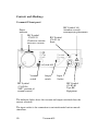
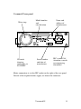
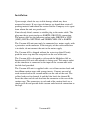
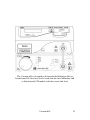
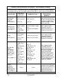
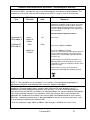
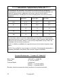
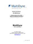
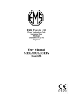
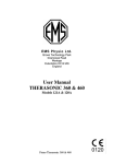
E M S P h ys i o L td .
Grove Technology Park
Downsview Road
Wantage
Oxfordshire OX12 9FE
England
User Manual
VACUUM 655
Model 115
2
Vacuum 655
General Information
This manual provides the necessary information for the installation
and operation of the Vacuum 655 unit.
These instructions must be studied before putting the unit into
operation.
The information contained in this manual is subject to change
without notice.
No part of this manual may be photocopied, reproduced or translated
into another language without the prior written consent of EMS
Physio Ltd.
The Vacuum 655 unit is designed for use with the Interferential 955
and 960 and the Multidyne 965 and 970 units.
The Vacuum 655 unit provides a convenient form of electrode
application for interferential therapy. The cup electrodes with their
sponge inserts are held in place by a partial vacuum. Both the
vacuum and the electrical connection to each cup are provided by a
single lead.
It is intended that the Vacuum 655 unit is only used by qualified
healthcare professionals such as physiotherapists who have received
training in electrotherapy.
Record of Amendments
ISSUE
1
2
3
4
5
6
COMMENTS
Initial Issue
Revised Company Name
Revised
EMC Tables added
Essential Performance list added
Declaration of conformity updated
Vacuum 655
DATE
14/12/2005
14/09/2006
01/10/2007
31/01/2008
16/09/2010
31/09/2012
3
EC Declaration of Conformity
EMS Physio Ltd
Grove Technology Park
Downsview Road
Wantage
Oxfordshire
OX12 9FE
United Kingdom
Declares that the following medical device is in
conformity with the essential requirements and
provisions of Council Directive 93/42/EEC and is
subject to the procedure set out in Annex 2 of Directive
93/42/EEC under the supervision of Notified Body
Number 0120, SGS United Kingdom Ltd.
Class IIa according to Annex IX of 93/42/EEC
Product Name
Vacuum 655
Model Numbers
115
Signature
4
Position
Quality Assurance Manager
Date
30 September 2012
First issued
14 December 2005
Vacuum 655
Contents
page
1
Title
General Information
3
Record of Amendments
3
Declaration of Conformity to 93/42/EEC
4
Contents
5
Warranty
6
Introduction
7
Contraindications
7
Technical Specification
8
Controls and Markings
10
Installation
14
Operating Instructions
16
Maintenance
18
EMC Tables
19
Vacuum 655
5
Warranty
EMS Physio Ltd., (hereinafter called the company) product is
warranted against defects in materials and workmanship for a period
of two years from the date of shipment. The Company will at its
option, repair or replace components which prove to be defective
during the warranty period, provided that the repairs or replacements
are carried out by the Company or its approved agents.
The Company will consider itself responsible for the effects on
safety, reliability and performance of the product:only if assembly operations, re-adjustments, modifications or
repairs are carried out by persons authorised by it,
only if the product is used in accordance with the instructions
for use,
only if the electrical installation of the relevant room complies
with the appropriate national requirements.
Should the product be returned to the Company for repair it must be
sent carriage paid.
Consumable items, for example, electrodes, electrode covers and
batteries, are excluded from the above warranty.
6
Vacuum 655
Introduction
The Vacuum 655 unit provides a convenient form of electrode
application for interferential therapy. The cup electrodes with their
sponge inserts are held in place by a partial vacuum. Both the
vacuum and the electrical connection to each cup are provided by a
single lead.
This method of electrode application is particularly suitable when
treating relatively flat, smooth areas of the body such as the back
where the cups may be attached quickly and easily. Also, this
method is useful when treating relatively immobile patients, as the
electrodes may be applied with the patient in a comfortable position
without having to be moved for the application of velcro bandages.
With the Vacuum 655 unit the vacuum may be set to a convenient
and comfortable level with a front panel control.
Connection to an interferential unit is made from the socket on the
front of the Vacuum 655 unit, using the link lead provided. Two or
four pole electrode applications may be used.
Both the vacuum and electrical connections are switched by the
vacuum unit.
A pulsed vacuum mode is provided to further reduce the likelihood
of bruising due to the vacuum. Two pulse rates are provided.
Contraindications
Vacuum electrodes should not be used on elderly patients with thin
papery skin leading to contact difficulty and bruising.
Vacuum electrodes are not suitable for patients who are taking
steroids because of the likelihood of bruising.
Vacuum 655
7
Technical Specification
General
Power Input
Classification (EN60601-1)
Mains Fuses
Size (height x width x depth)
Weight
Vacuum
Vacuum Modes
100-240 Vac 50/60 Hz
Class 1, Type BF
2 x T630 mA (5 x 20 mm)
65 x 210 x 190 mm
(excluding water trap)
1.5 kg
0 – 0.5 bar
Continuous,
Pulsed – 1 s period
Pulsed – 2 s period
The Vacuum 655 unit is designed to operate from any 50/60 Hz
single phase supply between 100 and 240 Vac capable of supplying
70 VA. Connection is via an IEC socket at the rear of the unit.
All information on model, serial number, and month/year of
manufacture is located on the rear panel.
Each Vacuum 655 unit is supplied with a detachable mains cable,
spare fuses, a set of four 60mm suction cups and suction leads, a link
lead for connection to an Interferential 955 or a Multidyne 965 unit
and this manual.
The Vacuum 655 unit has been designed to meet the requirements of
BS EN 60601-1:1990 (BS5724:Part 1:1989) "Medical Electrical
Equipment, Part 1:General requirements for Safety".
Environmental Conditions for Transport and Storage
Temperature
-10 to +35 C
Relative Humidity
5 to 95%
Atmospheric Pressure
500 to 1060 hPa
8
Vacuum 655
Accessories
Catalogue
Number
PMA3066
SLA3066
SLA3067
NC3068
NC3068A
NC3069
NC3069A
NC3070
EMS157
Description
Link Lead to Interferential 960 or Multidyne 970
Link Lead to Interferential 955 or Multidyne 965
Link Lead to connect to Medi-Link Interferential
Pair of 60mm suction cups (one yellow, one blue)
Pair of sponge inserts for 60mm suction cups
Pair of 100mm suction cups (one yellow, one blue)
Pair of sponge inserts for 100mm suction cups
Set of 4 suction leads
SoLo Treatment Trolley
Supplied with each unit is a detachable mains lead complete suitable
for the country to which it is delivered. Replacement or additional
mains leads are shown below.
EMS Part Number
6-85
6-112
6-119
Description
UK mains lead
European mains lead
North America mains lead
For other countries contact EMS Physio or the agent from whom the
unit was purchased.
Environmental
At the end its life, the Vacuum 655 should not be disposed of as
unsorted general waste. Advice on appropriate disposal is available
from EMS Physio Ltd.
Vacuum 655
9
Controls and Markings
Vacuum 655 front panel
IEC Symbol 348
Attention, consult
accompanying documents
Power
indicator
IEC Symbol
878-02-25
Clockwise rotation
increases vacuum
Vacuum
switch
IEC Symbol
878-01-36
Input
Output
switch
Input
Socket
IEC Symbol
878-02-03
Type BF
Equipment
IEC Symbol
878-02-08
"OFF" position of
vacuum control
The indicator lights above the vacuum and output switched show the
current selection.
The input socket is for connection to an interferential unit or muscle
stimulator.
10
Vacuum 655
Vacuum 655 rear panel
Water trap
CE mark
showing
conformity to
93/42/EEC
Model number
and
classification
Serial number
and date of
manufacture
Name and
address of
manufacturer
IEC symbol 348
Attention, consult
accompanying
documents
Mains connection is via the IEC socket on the right of the rear panel.
Details of the required mains supply are above the connector.
Vacuum 655
11
Vacuum 655 output panel
Channel A
suction outputs
IEC Symbol
878-02-03
Type BF
Equipment
12
Channel B
suction outputs
IEC Symbol
878-01-37
Output
Water trap
IEC Symbol 348
Attention, consult
accompanying documents
Vacuum 655
Vacuum 655 Accessories
Link Lead (SLA3066)
Suction Lead (2 blue, 2 Yellow NC3070)
Suction Cup (2 blue, 2 Yellow 2xNC3068)
Vacuum 655
13
Installation
Upon receipt, check for any visible damage which may have
occurred in transit. If any signs of damage are found then retain all
packing material and inform the carrier and the Company or its agent
from whom the unit was purchased.
If not already fitted, connect a suitable plug to the mains cable. The
plug must have provision for an EARTH (GROUND) connection.
The mains cable has the following colour code: BROWN is LIVE
(LINE), BLUE is NEUTRAL and GREEN/YELLOW is EARTH.
The Vacuum 655 unit must only be connected to a mains supply with
a protective earth conductor. If the integrity of the earth connection
is in doubt, do not connect the unit to the mains supply
The Vacuum 655 is shipped without the water trap fitted. Firmly
push the water trap into the receptacle on the rear of the unit.
The Vacuum 655 is designed to sit beneath the Multidyne 965 or
Interferential 955 unit with which it is being used. The output socket
of the stimulator is connected to the input of the vacuum unit with
the link lead provided.
The Vacuum 655 unit is supplied with a set of four suction leads and
four 60mm suction cups with sponge inserts. Connect one end of
each suction lead to the vacuum outlets on the side of the unit. The
yellow leads are for channel A and the blue leads for channel B.
Insert the other end of each lead into the connector at the rear of the
suction cups. The connectors at each end of the suction leads are a
simple push fit and provide both vacuum and electrical connection to
the cups.
14
Vacuum 655
The Vacuum 655 is designed to fit beneath the Multidyne 965 or
Interferential 955 but may also be used with the later Multidyne 960
or Interferential 970 models with the correct link lead.
Vacuum 655
15
Operating Instructions
Connect the mains cable to the IEC socket on the rear of the unit and
to a suitable power outlet. The unit will turn on with all the LED
indicators on. One by one the LED indicators will turn off to leave
only the power indicator, the continuous vacuum LED and the 2 pole
LED on. Make sure that the vacuum control is in the off position.
Insert the suction leads into the outlets on the side of the unit and the
suction cups as described in the installation section of this manual.
Make sure that the Vacuum 655 input is connected to the output
socket of the stimulator.
Switch on the stimulator being used with the Vacuum 655 and select
the required treatment according to its operating instructions. Do not
energise the output of the stimulator.
Wet the suction cup sponge inserts with water and squeeze until they
are wet but not dripping. In soft water areas it may be necessary to
add a small amount of sodium bicarbonate to the water to ensure low
contact impedance. Insert the sponges into the cups ready for
application to the patient.
Confirm that 2 pole is selected and advance the Vacuum Control to
greater than 50%. Attach the 2 pole suction cups (one yellow and
one blue) in turn by pressing them firmly on to the patient and
waiting for the vacuum to hold them. In areas with body hair it may
be necessary to wet the rim of each suction cup to effect a seal
between the cup and the skin.
When the 2 pole suction cups have been attached satisfactorily to the
patient and if a four-pole treatment is to be used, select 4 pole by
pressing the output switch – the 2 pole indicator will be extinguished
and the 4 pole indicator will light. Attach the two remaining suction
cups in the same way.
The vacuum may now be reduced to a comfortable level using the
vacuum control.
16
Vacuum 655
Should a pulsed vacuum mode of operation be desired press the
vacuum switch. Pressing once selects a one second pulse period and
pressing twice will selects a two second pulse period as shown by the
LED indicator. Pressing the vacuum switch again returns to
continuous vacuum. It is advisable to select pulsed operation before
reducing the vacuum significantly to prevent the suction cups
becoming detached in the low vacuum part of the pulse.
Having successfully applied the suction cups and set the vacuum
mode and level, energise the output of the stimulator.
If the suction cups become detached during treatment the stimulator
output must be de-energised before attempting to reconnect the cup
electrodes. With the Multidyne 965 and Interferential 955 units set to
constant current, the output will normally be terminated when the
cups become detached and an alarm will sound. In constant voltage
modes the output must be reduced to zero manually.
At the end of treatment, return the output control of the stimulator to
its off position before removing the suction cups. With the
Multidyne 965 and Interferential 955 units the output is
automatically set to zero at the end of the treatment time.
To remove the suction cups, return the Vacuum Control to the off
position. The cups will detach themselves as the vacuum under the
cups is vented to the atmosphere.
Note that the contact areas of the 60 mm and 100 mm suction cups
are approximately 25 and 50 cm2 respectively. The maximum
recommended current density is 2 mA/cm2 and hence the current
applied with the suction cups should not exceed 50 mA rms and 100
mA rms respectively. When using interferential therapy units this
corresponds to 70 and 140 mA peak for the 60 mm and 100 mm cups
respectively.
Excess water from the sponges is captured by the water trap on the
rear of the Vacuum 655. It is recommended that the water trap is
emptied between treatments. To remove the water trap for emptying,
firmly pull it away from the unit.
Vacuum 655
17
Maintenance
The suction cups and sponges may be disinfected using a 70% v/v
aqueous solution of isopropyl alcohol. They are NOT suitable for
steam sterilisation or treatment with disinfectants containing sodium
hypochlorite.
N.B. Isopropyl alcohol is flammable and should be kept away from
naked flames. Isopropyl alcohol must not be brought into contact
with eyes or mouth.
The Vacuum 655 may be cleaned by wiping over with a clean damp
cloth. The use of abrasive materials and cleaning solvents should be
avoided.
Regularly (at least monthly) inspect the suction leads, cups, cables
and connectors for damage.
The Vacuum 655 should be serviced at least annually by qualified
personnel.
If, during set-up, the front panel LEDs all begin to flash in unison,
this is an error message implying that the internal pressure sensor has
detected an out of range value. Switch the unit off, check that the
leads and cups are correctly connected and not obstructed, and restart the unit. If this error message persists, contact qualified service
personnel.
The mains fuses are located on the rear panel in a compartment
below the mains inlet. The compartment cannot be opened unless the
mains lead is removed from the IEC socket. Information on fuse type
and rating is given on the rear panel of the unit and in the Technical
Specification section of this manual.
If the mains fuses continue to blow then EMS qualified Service
personnel must be called in.
There are no user serviceable parts inside the unit and it should
not be opened.
Full servicing instructions are available on request.
18
Vacuum 655
EMC Tables
1
2
3
4
6
7
8
Guidance and manufacturers declaration – electromagnetic emissions
The Vacuum 655 is intended for use in the electromagnetic environment
specified below. The customer or the user of the 655 should assure that it is
used in such an environment.
Electromagnetic environment Emissions Test
Compliance
guidance
The 655 uses RF energy only for its
internal function. Therefore, its RF
RF emissions
Group 1
emissions are very low and are not
CISPR 11
likely to cause any interference in
nearby electronic equipment.
RF emissions
Class A
CISPR 11
Harmonic
not
The 655 is suitable for use in all
emissions
applicable
establishments other than domestic and
IEC 6100-3-2
those directly connected to the public
low-voltage power supply network that
Voltage
supplies buildings used for domestic
fluctuations
not
purposes.
Flicker emissions
applicable
IEC 61000-3-3
Vacuum 655
19
Guidance and manufacturers declaration – electromagnetic immunity
The Vacuum 655 is intended for use in the electromagnetic environment specified below.
The customer or the user of the 655 should assure that it is used in such an environment.
Immunity test
Electrostatic
discharge
(ESD)
IEC 61000-4-2
Electrical fast
transient/burst
IEC61000-4-4
IEC 60601
test level
±6 kV contact
±6 kV contact
±8 kV air
±8 kV air
±2 kV for
power supply
lines
±2 kV for power supply
lines
±1 kV for
input/output
lines
Surge
±1 kV line(s)
to line(s)
IEC61000-4-5
±2 kV line(s)
to earth
<5% UT
(>95% dip in
UT)
For 0,5 cycle
Voltage dips,
short
interruptions
and voltage
variations on
power supply
input lines
IEC 61000-4-11
Compliance level
40% UT
(60% dip in
UT)
For 5 cycles
70% UT
(30% dip in
UT)
For 25 cycles
<5% UT
(>95% dip in
UT)
For 5 sec
±1 kV for input/output
lines
±1 kV line(s) to line(s)
±2 kV line(s) to earth
<5% UT
(>95% dip in UT)
For 0,5 cycle
40% UT
(60% dip in UT)
For 5 cycles
70% UT
(30% dip in UT)
For 25 cycles
<5% UT
(>95% dip in UT)
For 5 sec
Electromagnetic
Environment
guidance
Floors should be wood,
concrete or ceramic tile.
If floors are covered with
synthetic material, the
relative humidity should
be at least 30%.
Mains power quality
should be that of a
typical commercial or
hospital environment.
Mains power quality
should be that of a
typical commercial or
hospital environment.
Mains power quality
should be that of a
typical commercial or
hospital environment. If
the user of the 655
requires continued
operation during power
mains interruptions, it is
recommended that the
655 be powered from an
uninterruptible power
supply or a battery.
Power frequency
magnetic field should be
at levels characteristic of
3 A/m
3 A/m
a typical location in a
typical commercial or
hospital environment.
NOTE UT is the a.c. mains voltage prior to application of the test level.
Power
frequency
(50/60 Hz)
Magnetic field
IEC 61000-4-8
20
Vacuum 655
Guidance and manufacturers declaration – Electromagnetic immunity.
The Vacuum 655 is intended for use in the electromagnetic environment specified below. The
customer or user of the Vacuum 655 should assure that it is used in such an environment.
Immunity
Test
IEC 60601
Test level
Compliance
level
Electromagnetic Environment
Guidance
Portable and mobile RF communications
equipment should be used no closer to any part
of the Vacuum 655, including cables, than the
recommended separation distance calculated
from the equation applicable to the frequency of
the transmitter.
Recommended separation distance
Conducted RF
IEC61000-4-6
3Vrms
150kHz to
80MHz
3V
Radiated RF
IEC61000-4-3
3V/m
3V/m
d=3.5√P/V1
d=3.5√P/E1 80MHz to 800MHz
d=7√P/E1 800MHz to 2.5GHz
where P is the maximum output power rating of
the transmitter according to the manufacturer
and d is the recommended separation distance
in metres (m).
80MHz to
2.5GHz
Field strengths from fixed RF transmitters, as
determined by an electromagnetic site surveya
should be less than the compliance level in each
frequency rangeb.
Interference may occur in the vicinity of
equipment marked with the following symbol:
NOTE 1 At 80MHz and 800MHz the higher frequency range applies.
NOTE 2 These guidelines may not apply in all situations. Electromagnetic propagation is
affected by absorption and reflection from structures, objects and people.
a
Field strengths from fixed transmitters, such as base stations for radio (cellular/cordless)
telephones and land mobile radios, amateur radio, AM and FM radio broadcast and TV
broadcast cannot be predicted theoretically with accuracy. To assess the electromagnetic
environment due to fixed RF transmitters, an electromagnetic site survey should be considered.
If the measured field strength in the location in which the Vacuum 655 is used exceeds the
applicable RF compliance level above, the Vacuum 655 should be observed to verify normal
operation. If abnormal performance is observed additional measures may be necessary, such
as re-orienting or relocating the Vacuum 655.
b
Over the frequency range 10kHz to 80Mhz, field strengths should be less than 3 V/m.
Vacuum 655
21
Recommended separation distances between portable and mobile RF
communications equipment and the Vacuum 655
The Vacuum 655 is intended for use in an electromagnetic environment in which radiated
RF disturbances are controlled. The customer or user of the 655 can help prevent
electromagnetic interference by maintaining a minimum distance between portable and
mobile RF communications equipment (transmitters) and the Vacuum 655 as
recommended below, according to the maximum output power of the communications
equipment.
150kHz to 80MHz
d=3.5√P/V1
80MHz to 800MHz
d=3.5√P/E1
800MHz to 2.5GHz
d=7√P/E1
0.01
0.12
0.12
0.23
0.1
0.38
0.38
0.73
1
1.2
1.2
2.3
10
3.8
3.8
7.3
100
12
12
23
For transmitters rated at a maximum output power not listed above, the recommended
separation distance d in meters (m) can be estimated using the equation applicable to the
frequency of the transmitter, where P is the maximum output power rating in watts (W)
according to the transmitter manufacturer.
NOTE 1 At 80MHz and 800MHz the separation distance for the higher frequency range
applies.
NOTE 2 These guidelines may not apply in all situations. Electromagnetic propagation is
affected by absorption and reflection from structures, objects and people.
Essential Performance – Vacuum 655, Model 115
Power Input
Vacuum
Vacuum Modes
100-240 Vac 50/60 Hz
0 – 0.5 bar (±20%)
Continuous,
Pulsed – 1 s period (±20%)
Pulsed – 2 s period (±20%)
Provides electrical connection from stimulator to vacuum electrodes.
22
Vacuum 655