1
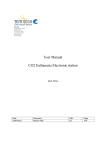
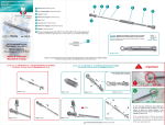
USER MANUAL
Each burner is individually inspected.
To light the burner, turn the control knob (n°5) anti-clockwise, and keep it
pressed. Bring a flame or a lighter device near the burner and wait for a few
seconds. After ignition, release the control knob.
To switch off the burner, turn completely the knob (n°5) clockwise.
INSTALLATION AND USER MANUAL
If the flame disappears it's probably due to a too high gas pressure. On the
contrary, when gas pressure is too low, flames have too much yellow tips.
In both cases, we recommend to have the hob checked and adjusted by a
specialist.
The hob must be installed and used in areas with adequate ventilation.
Always keep ventilation holes opened when using the hob. Never use the
hob as a room heater.
REF 53281 : Counter-top hob 1 burner on gimbals
CLEANING
REF 53282 : Counter-top hob 2 burners on gimbals
REF 53283 : Counter-top hob 2 burners with safety glass cover
REF 53284 : Counter-top hob 3 burners with safety glass cover
REF 53285 : 1 burner hob + sink set
REF 53286 : 2 burner hob + sink set
WWW.PLASTIMO.COM
Clean the hob with a suitable commercial product such as a dishwashing
liquid. Burners and knobs must be cleaned with cloth moistened with water :
do not use chimical nor a cleaner which contains abrasives.
INSPECTION AND MAINTENANCE OF THE APPLIANCE MUST
BE CARRIED OUT BY A LIQUID GAS SPECIALIST. A
CERTIFICATION OF THE JOB CARRIED OUT MUST BE ISSUED
AFTER ANY REPAIR OR MODIFICATION PERFORMED. NO
ALTERATIONS OR ADJUSTMENTS SHOULD BE MADE TO THIS
APPLIANCE WITHOUT THE AUTHORISATION OF THE
MANUFACTURER OR FROM ONE OF HIS OFFICIAL.
Réf. 53281: Hob 1 burner on gimbals
Réf. 53282 : Hob 2 burners on gimbals
Réf. 53283: 2 burners + glass cover
Réf. 53284 : 3 burners + glass cover
MOUNTING INSTRUCTIONS
MOUNTING INSTRUCTIONS
1. Fasten the hob on the work top with the 4
1. Install the pan clamps (1) and insert the wing
nut(s) n° 4 (cf. fig.1).
2. Fasten the gimbals on the hob with the screws,
nuts and washers supplied (cf. fig.1).
3. Fasten the gimbals on the work top with the screws supplied (cf. fig.2).
4. Insert the wing nut in the right gimbal to stop the swing (cf. fig.3).
5. Mount the knob(s) n°5.
The appliance must be connected to the gas supply with a non adjustable
pressure regulator which complies with ISO 10239 directive. This regulator
reduces the gas pressure between the gas cylinder and the appliance and
must be designed for the following standardized pressure :
BUTANE : 28 mbar (11.2 wg)
PROPANE : 37 mbar (14.8 wg)
screws and 4 cams supplied, as described on
figure 1.
2. Stick a shock absorber on the head of each front screw.
The appliance must be connected to the gas supply with a non adjustable
pressure regulator which complies with ISO 10239 directive. This regulator
reduces the gas pressure between the gas cylinder and the appliance and
must be designed for the following standardized pressure :
BUTANE : 28 mbar (11.2 wg)
PROPANE : 37 mbar (14.8 wg)
Figure 1 :
Figure 1 :
Réf. 53285: 1 burner hob + sink set
Réf. 53286 : 2 burners hob + sink set
MOUNTING INSTRUCTIONS
Figure 2 :
Figure 3 :
1.
Mount the control knob(s) n°1.
The appliance must be connected to the gas supply with a
non adjustable pressure regulator which complies with ISO
10239 directive. This regulator reduces the gas pressure
between the gas cylinder and the appliance and must be
designed for the following standardized pressure :
BUTANE : 28 mbar (11.2 wg)
PROPANE : 37 mbar (14.8 wg)