1
www.3grouterstore.co.uk
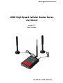
GWR High Speed Cellular Router Series
User Manual
version 1.1.
Date: June 2014.
UK SALES : 0800 508 8366
User Manual
Content
LIST OF FIGURES .........................................................................................................................................................4
LIST OF TABLES ...........................................................................................................................................................7
DESCRIPTION OF THE LTE ROUTER SERIES..............................................................................................................8
TYPICAL APPLICATION ...................................................................................................................................... 9
TECHNICAL PARAMETERS ................................................................................................................................ 10
PROTOCOLS AND FEATURES ............................................................................................................................. 11
PRODUCT OVERVIEW ..................................................................................................................................... 13
Front panel ........................................................................................................................................................13
Back panel .........................................................................................................................................................13
Top Panel...........................................................................................................................................................14
PUTTING INTO OPERATION .............................................................................................................................. 16
DECLARATION OF CONFORMITY ........................................................................................................................ 17
DEVICE CONFIGURATION ........................................................................................................................................18
DEVICE CONFIGURATION USING WEB APPLICATION ..........................................................................................18
ADD/REMOVE/UPDATE MANIPULATION IN TABLES ................................................................................................. 19
SAVE/RELOAD CHANGES ................................................................................................................................. 19
STATUS INFORMATION ................................................................................................................................... 20
Status – General ................................................................................................................................................20
Status – Network Information ..........................................................................................................................20
Status – DHCP ...................................................................................................................................................21
Status – WAN Information ................................................................................................................................21
Status – Firewall ................................................................................................................................................22
Status – Routes..................................................................................................................................................23
Status – Router Monitoring ..............................................................................................................................23
SETTINGS – NETWORK .................................................................................................................................... 24
SETTINGS – DHCP SERVER .............................................................................................................................. 25
SETTINGS – WAN SETTING .............................................................................................................................. 27
SETTINGS – WIRELESS .................................................................................................................................... 31
SETTINGS – ROUTING ..................................................................................................................................... 33
Port translation ............................................................................................................................................................... 34
SETTINGS – DYNAMIC ROUTING PROTOCOL ......................................................................................................... 35
Routing Information Protocol (RIP) ..................................................................................................................35
RIP routing engine for the GWR-HS Router....................................................................................................................... 36
Virtual Router Redundancy Protocol (VRRP) ....................................................................................................37
SETTINGS – VPN SETTINGS .............................................................................................................................. 39
Generic Routing Encapsulation (GRE) ..............................................................................................................39
GRE Keepalive.................................................................................................................................................................. 40
Internet Protocol Security (IPSec) .....................................................................................................................41
OpenVPN ...........................................................................................................................................................46
Point-to-Point Tunneling Protocol (PPTP)........................................................................................................50
Layer2 Tunneling Protocol (L2TP) ....................................................................................................................51
SETTINGS – FIREWALL – IP FILTERING ................................................................................................................. 53
SETTINGS – FIREWALL – MAC FILTERING............................................................................................................. 54
DMZ HOST ................................................................................................................................................ 55
SETTINGS – DYNDNS .................................................................................................................................... 56
SETTINGS – SERIAL PORT ................................................................................................................................ 58
Serial port over TCP/UDP settings ....................................................................................................................58
Modbus Gateway settings ................................................................................................................................60
SMS – SMS REMOTE CONTROL ....................................................................................................................... 62
SMS – Send SMS................................................................................................................................................63
MAINTENANCE ............................................................................................................................................. 64
Maintenance – Device Identity Settings...........................................................................................................64
Geneko GWR High Speed Router Series
2
User Manual
Maintenance – Administrator Password ..........................................................................................................64
Maintenance – Date/Time Settings ..................................................................................................................66
Maintenance – Diagnostics ..............................................................................................................................67
Maintenance – Update Firmware .....................................................................................................................67
Maintenance – Settings Backup .......................................................................................................................68
Import Configuration File ................................................................................................................................................ 68
Export Configuration File................................................................................................................................................. 68
Maintenance – Default Settings .......................................................................................................................69
Maintenance – System Reboot.........................................................................................................................69
MANAGEMENT – COMMAND LINE INTERFACE ....................................................................................................... 70
MANAGEMENT – REMOTE MANAGEMENT ............................................................................................................ 71
MANAGEMENT – CONNECTION MANAGER ........................................................................................................... 72
Getting started with the Connection Wizard ...................................................................................................72
MANAGEMENT – SIMPLE MANAGEMENT PROTOCOL (SNMP) ................................................................................... 76
MANAGEMENT – LOGS ................................................................................................................................... 77
LOGOUT ..................................................................................................................................................... 78
CONFIGURATION EXAMPLES ..................................................................................................................................79
GWR-HS ROUTER AS INTERNET ROUTER ............................................................................................................. 79
GRE TUNNEL CONFIGURATION BETWEEN TWO GWR-HS ROUTERS ............................................................................. 80
GRE TUNNEL CONFIGURATION BETWEEN GWR-HS ROUTER AND THIRD PARTY ROUTER.................................................... 84
IPSEC TUNNEL CONFIGURATION BETWEEN TWO GWR-HS ROUTERS ........................................................................... 87
Scenario #1 ........................................................................................................................................................88
Scenario #2 ........................................................................................................................................................94
IPSEC TUNNEL CONFIGURATION BETWEEN GWR-HS ROUTER AND CISCO ROUTER........................................................ 100
IPSEC TUNNEL CONFIGURATION BETWEEN GWR-HS ROUTER AND JUNIPER SSG FIREWALL ............................................. 105
OPENVPN TUNNEL BETWEEN GWR-HS ROUTER AND OPENVNP SERVER ................................................................... 115
PORTFORWARDING – EXAMPLE ....................................................................................................................... 118
SERIAL PORT – EXAMPLE ............................................................................................................................... 120
FIREWALL – EXAMPLE................................................................................................................................... 123
SMS MANAGEMENT – EXAMPLE ...................................................................................................................... 130
DEFINING KEEPALIVE FUNCTIONALITY ............................................................................................................... 131
APENDIX ..................................................................................................................................................................132
A. HOW TO ACHIEVE MAXIMUM SIGNAL STRENGTH WITH GWR-HS ROUTER?............................................................. 132
Antenna placement ........................................................................................................................................133
Antenna Options.............................................................................................................................................133
Geneko GWR High Speed Router Series
3
User Manual
List of Figures
Figure 1 – GWR-HS Router.................................................................................................................................................8
Figure 2 – GWR-HS Router front panel............................................................................................................................13
Figure 3 – GWR-HS Router back panel (without WiFi supported)..................................................................................14
Figure 4 – GWR-HSW Router back panel (WiFi supported) ............................................................................................14
Figure 5 – GWR-HS Router top panel side
Figure 6 – GWR-HSW Router top panel side ....15
Figure 7 – Declaration of conformity ..............................................................................................................................17
Figure 8 – User authentication ........................................................................................................................................18
Figure 9 – General router information ............................................................................................................................20
Figure 10 – Network Information....................................................................................................................................21
Figure 11 – DHCP Information ........................................................................................................................................21
Figure 12 – WAN Information..........................................................................................................................................22
Figure 13 – Firewall Information .....................................................................................................................................22
Figure 14 – Information about active routes ..................................................................................................................23
Figure 15 – Router monitoring........................................................................................................................................23
Figure 16 – Network parameters configuration page ....................................................................................................24
Figure 17 – DHCP Server configuration page .................................................................................................................26
Figure 18 – WAN Settings configuration page ...............................................................................................................27
Figure 19 – Wireless configuration page ........................................................................................................................31
Figure 20 – Routing configuration page.........................................................................................................................33
Figure 21 – RIP configuration page.................................................................................................................................35
Figure 22 – VRRP configuration page .............................................................................................................................37
Figure 23 – GRE tunnel parameters configuration page ................................................................................................40
Figure 24 – IPSec Summary screen .................................................................................................................................41
Figure 25 – IPSec Settings ...............................................................................................................................................42
Figure 26 – OpenVPN example .......................................................................................................................................46
Figure 27 – OpenVPN Summary screen ..........................................................................................................................46
Figure 28 – OpenVPN configuration page ......................................................................................................................49
Figure 29 – OpenVPN network topology........................................................................................................................49
Figure 30 – PPTP configuration page..............................................................................................................................50
Figure 31 – L2TP configuration page ..............................................................................................................................51
Figure 32 – Firewall configuration page .........................................................................................................................54
Figure 33 – MAC filtering configuration page ................................................................................................................55
Figure 34 – DMZ Host configuration page .....................................................................................................................55
Figure 35 – DynDNS settings...........................................................................................................................................56
Figure 36 – Serial Port Settings initial menu ...................................................................................................................58
Figure 37 – Serial Port configuration page .....................................................................................................................59
Figure 38 – Modbus gateway configuration page .........................................................................................................61
Figure 39 – SMS remote control configuration ..............................................................................................................63
Figure 40 – Send SMS ......................................................................................................................................................63
Figure 41 – Device Identity Settings configuration page...............................................................................................64
Figure 42 – Router Management configuration page....................................................................................................65
Figure 43 – Date/Time Settings configuration page ......................................................................................................66
Figure 44 – Diagnostic page............................................................................................................................................67
Figure 45 – Update Firmware page.................................................................................................................................67
Figure 46 – Export/Import the configuration on the router...........................................................................................68
Figure 47 – File download ...............................................................................................................................................68
Figure 48 – Default Settings page...................................................................................................................................69
Figure 49 – System Reboot page ....................................................................................................................................69
Figure 50 – Command Line Interface..............................................................................................................................70
Figure 51 – Remote Management...................................................................................................................................71
Figure 52 – Connection Manager....................................................................................................................................72
Figure 53 – Connection Wizard – Initial Step..................................................................................................................73
Geneko GWR High Speed Router Series
4
User Manual
Figure 54 – Connection Wizard – Router Detection .......................................................................................................74
Figure 55 – Connection Wizard – LAN Settings ..............................................................................................................74
Figure 56 – Connection Wizard – WAN Settings.............................................................................................................75
Figure 57 – SNMP configuration page ............................................................................................................................76
Figure 58 – Syslog configuration page ...........................................................................................................................77
Figure 59 – GWR-HS Router as Internet router ...............................................................................................................79
Figure 60 – GRE tunnel between two GWR-HS Routers .................................................................................................80
Figure 61 – Network configuration page for GWR-HS Router 1.....................................................................................80
Figure 62 – GRE configuration page for GWR-HS Router 1 ............................................................................................81
Figure 63 – Routing configuration page for GWR-HS Router 1......................................................................................81
Figure 64 – Network configuration page for GWR-HS Router 2.....................................................................................82
Figure 65 – GRE configuration page for GWR-HS Router 2 ............................................................................................82
Figure 66 – Routing configuration page for GWR-HS Router 2......................................................................................83
Figure 67 – GRE tunnel between Cisco router and GWR-HS Router ..............................................................................84
Figure 68 – Network configuration page........................................................................................................................85
Figure 69 – GRE configuration page ...............................................................................................................................86
Figure 70 – Routing configuration page.........................................................................................................................86
Figure 71 – IPSec tunnel between two GWR-HS Routers ...............................................................................................87
Figure 72 – Network configuration page for GWR-HS Router 1.....................................................................................88
Figure 73 – IPSEC configuration page I for GWR-HS Router 1 ........................................................................................89
Figure 74 – IPSec configuration page II for GWR-HS Router 1........................................................................................89
Figure 75 – IPSec configuration page III for GWR-HS Router 1.......................................................................................90
Figure 76 – IPSec start/stop page for GWR-HS Router 1.................................................................................................90
Figure 77 – Network configuration page for GWR-HS Router 2.....................................................................................91
Figure 78 – IPSEC configuration page I for GWR-HS Router 2 ........................................................................................92
Figure 79 – IPSec configuration page II for GWR-HS Router 2........................................................................................92
Figure 80 – IPSec configuration page III for GWR-HS Router 2.......................................................................................92
Figure 81 – IPSec start/stop page for GWR-HS Router 2.................................................................................................93
Figure 82 – Network configuration page for GWR-HS Router 1.....................................................................................94
Figure 83 – IPSEC configuration page I for GWR-HS Router 1 ........................................................................................95
Figure 84 – IPSEC configuration page II for GWR-HS Router 1 .......................................................................................96
Figure 85 – IPSEC configuration page III for GWR-HS Router 1 ......................................................................................96
Figure 86 – IPSec start/stop page for GWR-HS Router 1.................................................................................................96
Figure 87 – Network configuration page for GWR-HS Router 2.....................................................................................97
Figure 88 – IPSEC configuration page I for GWR-HS Router 2 ........................................................................................98
Figure 89 – IPSEC configuration page II for GWR-HS Router 2 .......................................................................................98
Figure 90 – IPSEC configuration page III for GWR-HS Router 2 ......................................................................................99
Figure 91 – IPSec start/stop page for GWR-HS Router 1.................................................................................................99
Figure 92 – IPSec tunnel between GWR-HS Router and Cisco Router .........................................................................100
Figure 93 – Network configuration page for GWR-HS Router......................................................................................100
Figure 94 – IPSEC configuration page I for GWR-HS Router.........................................................................................102
Figure 95 – IPSec configuration page II for GWR-HS Router ........................................................................................102
Figure 96 – IPSec configuration page III for GWR-HS Router .......................................................................................103
Figure 97 – IPSec start/stop page for GWR-HS Router..................................................................................................103
Figure 98 – IPSec tunnel between GWR-HS Router and Cisco Router .........................................................................105
Figure 99 – Network configuration page for GWR-HS Router......................................................................................106
Figure 100 – IPSEC configuration page I for GWR-HS Router.......................................................................................107
Figure 101 – IPSec configuration page II for GWR-HS Router ......................................................................................107
Figure 102 – IPSec configuration page III for GWR-HS Router .....................................................................................107
Figure 103 – IPSec start/stop page for GWR-HS Router ...............................................................................................108
Figure 104 – Network Interfaces (list) ...........................................................................................................................109
Figure 105 – Network Interfaces (edit)..........................................................................................................................109
Figure 106 – AutoKey Advanced Gateway....................................................................................................................110
Figure 107 – Gateway parameters ................................................................................................................................110
Figure 108 – Gateway advanced parameters ...............................................................................................................111
Geneko GWR High Speed Router Series
5
User Manual
Figure 109 – AutoKey IKE ..............................................................................................................................................111
Figure 110 – AutoKey IKE parameters...........................................................................................................................112
Figure 111 – AutoKey IKE advanced parameters..........................................................................................................112
Figure 112 – Routing parameters..................................................................................................................................113
Figure 113 – Policies from untrust to trust zone...........................................................................................................113
Figure 114 – Policies from trust to untrust zone...........................................................................................................114
Figure 115 – Multipoint OpenVPN topology ................................................................................................................115
Figure 116 – OpenVPN application settings .................................................................................................................116
Figure 117 – OpenVPN GWR-HS settings......................................................................................................................117
Figure 118 – Static routes on GWR-HS ..........................................................................................................................118
Figure 119 – Starting OpenVPN application .................................................................................................................118
Figure 120 – OpenVPN status on PC .............................................................................................................................118
Figure 121 – OpenVPN status on GWR-HS....................................................................................................................118
Figure 122– Portforwarding example ...........................................................................................................................119
Figure 123– GWR-HS portforwarding configuration ....................................................................................................119
Figure 124– Transparent serial connection ..................................................................................................................120
Figure 125– GWR-HS Serial port settings......................................................................................................................120
Figure 126– GWR-HS settings for Serial-to-IP conversion ............................................................................................121
Figure 127- Virtual COM port application .....................................................................................................................122
Figure 128– Settings for virtual COM port ....................................................................................................................122
Figure 129 – Firewall example.......................................................................................................................................124
Figure 130 – Initial firewall configuration on GWR-HS .................................................................................................124
Figure 131 – Filtering of Telnet traffic ...........................................................................................................................125
Figure 132 – Filtering of ICMP traffic.............................................................................................................................126
Figure 133 – Allowing ICMP traffic ................................................................................................................................126
Figure 134 – IPSec firewall rules ....................................................................................................................................127
Figure 135 – Allowing WEB access ................................................................................................................................128
Figure 136 – Outbound rule for WEB access.................................................................................................................129
Figure 137 – Complete firewall configuration ..............................................................................................................130
Figure 138– Configuration page for SMS management...............................................................................................131
Figure 139– Configuration page for GSM keepalive ....................................................................................................132
Geneko GWR High Speed Router Series
6
User Manual
List of Tables
Table 1 – Technical parameters.......................................................................................................................................10
Table 2 – GWR-HS Router features ..................................................................................................................................12
Table 3 – Network parameters ........................................................................................................................................24
Table 4 – DHCP Server parameters .................................................................................................................................25
Table 5 – WAN parameters ..............................................................................................................................................29
Table 6 – Advanced WAN Settings..................................................................................................................................31
Table 7 – Wireless Settings ..............................................................................................................................................32
Table 8 – Routing parameters .........................................................................................................................................34
Table 9 – RIP parameters .................................................................................................................................................36
Table 10 – VRRP parameters............................................................................................................................................38
Table 11 – GRE parameters..............................................................................................................................................40
Table 12 – IPSec Summary...............................................................................................................................................42
Table 13 – IPSec Parameters............................................................................................................................................45
Table 14 – OpenVPN parameters ....................................................................................................................................48
Table 15 – PPTP parameters ............................................................................................................................................51
Table 16 – L2TP parameters ............................................................................................................................................52
Table 17 – Firewall parameters .......................................................................................................................................54
Table 18 - MAC filtering parameters ...............................................................................................................................55
Table 19 – DynDNS parameters ......................................................................................................................................57
Table 20 – Serial Port over TCP/UDP parameters ...........................................................................................................59
Table 21 – Modbus gateway parameters........................................................................................................................60
Table 22 – Device Identity parameters ...........................................................................................................................64
Table 23 – Router Management......................................................................................................................................65
Table 24 – Date/time parameters....................................................................................................................................66
Table 25 – Command Line Interface parameters............................................................................................................70
Table 26 – Remote Management parameters ................................................................................................................71
Table 27 – SNMP parameters ..........................................................................................................................................76
Table 28 – Syslog parameters..........................................................................................................................................78
Geneko GWR High Speed Router Series
7
User Manual
Description of the LTE Router Series
GWR-HS routers represent a robust solution designed to provide remote connectivity across cellular
networks. Low transmission delay and very high data rates offered by existing cellular networks completely
eliminate the need for expensive wired infrastructure. GWR-HS series brings scalability of even most demanding
corporate networks on highest possible level. Installing a reliable, high performance backup solution for existing
land lines or satellite networks is now a simple task thanks to modern cellular networks. Therefore, no matter if the
goal is to provide primary internet access or backup solution for already existing network GWR-HS router series
represents a top rated solution.
Figure 1 – GWR-HS Router
There are practically no limits when it comes to possible application of GWR-HS routers. Wired
infrastructure is no longer necessary for building scalable and high performance systems. GWR-HS routers will
reduce the costs and speed up the ROI process for each one of possible applications. The list of most common
GWR-HS router applications is presented bellow.
Geneko GWR High Speed Router Series
8
User Manual
Typical application
Data collection and system supervision
• Extra–high voltage equipment monitoring,
• Running water, gas pipe line supervision,
• Centralized heating system supervision,
• Environment protection data collection,
• Flood control data collection,
• Alert system supervision,
• Weather station data collection,
• Power Grid,
• Oilfield,
• Light Supervision,
• Solar PV Power Solutions.
Financial and department store
• Connection of ATM machines to central site,
• Vehicle based bank service,
• POS,
• Vending machine,
• Bank office supervision.
Security
• Traffic control,
• Video Surveillance Solutions,
Other
• Remote Office Solution,
• Remote Access Solution.
There are numerous variations of each and every one of above listed applications. Therefore GENEKO
formed highly dedicated, top rated support team that can help you analyze your requirements and existing system,
chose the right topology for your new system, perform initial configuration and tests and monitor the complete
system after installation. Enhance your system performance and speed up the ROI with high quality cellular routers
and all relevant knowledge of GWR-HS support team behind you.
Geneko GWR High Speed Router Series
9
User Manual
Technical Parameters
EMC
LVD
Complies with
standards
R&TTE
Directive 2004/108/EC
EN 301 489–1 V1.6.1(2005–09)
EN 301 489–7 V1.3.1(2005–11)
EN 60950–1:2001(1st Ed.) and/or EN 60950–1:2001
Directive 1999/05/EC
ETSI EN 301 511 V9.0.2
EN 301 908–1 & EN 301 908–2(v2.2.1)
Directive 2002/95/EC
RoHS
EU Commission 2005/618/EC, 2005/717/EC, 2005/747/EC,
2006/310/EC, 2006/690/EC, 2006/691/EC and 2006/692/EC
Ethernet interface
Connector RJ–45
Standard: IEEE 802.3
Physical layer: 10/100Base–T
Speed: 10/100Mbps
Mode: full or half duplex
Other interfaces
1 x UART(RS–232C)
1 x USB Host
RF characteristics
RF Connector
Status LED
GWR402
GPRS
EDGE
UMTS
HSPA
LTE
LTE: 800/900/1800/2100/2600 MHz
UMTS/HSDPA/HSUPA: 900/2100MHz
GSM/GPRS/EDGE: Quad band, 850/900/1800/1900MHz
GPRS/EDGE multi–slot class 12, mobile station class B
LTE DL: 100 Mbps; UL: 50 Mbps
HSPA+ DL: 42 Mbps; UL: 5.76 Mbps
HSUPA DL: 7.2Mbps, HSDPA: UL: 5.76Mbps
UMTS DL: 384Kbps, UL: 384Kbps
EDGE DL: 236.8Kbps, UL: 236.8Kbps
GPRS DL: 85.6Kbps, UL: 85.6Kbps
SMA, 50Ω
Ethernet activity/network traffic
Power on
GSM link activity
Signal quality
WiFi
Power requirements
9 – 12VDC / 1000mA
Environmental
Operation: –10° C to 55° C (14° F to 131° F)
Storage: –20° C to +85° C (–4° F to +185° F)
Relative humidity: 5% to 95% (non–condensing)
Dimensions and
weight
Width/Length/Height: 95mm/135mm/35mm
Weight: 380g
Table 1 – Technical parameters
Geneko GWR High Speed Router Series
10
User Manual
Protocols and features
Features
Short description
Network
Routing
DHCP Server:
•
Static lease reservation
•
Address exclusions
RIPv2
VRRP
WiFi (for GWR402HSW models)
IP forwarding
DMZ support
SNMP v1,2c
NTP(RFC1305)
DynDNS
Firewall:
•
NAT
•
PAT
•
IP filtering
•
MAC filtering
Serial over TCP/UDP
Modbus serial/IP gateway
Static
DHCP Server support.
The Routing Information Protocol is a dynamic routing protocol used
in local and wide area networks.
VRRP protocol Increases the availability and reliability of routing
paths via automatic default gateway
WiFi interface with two modes supported – Access point and Station
IP, TCP, UDP packets from WAN to LAN.
DMZ host is a host on the internal network that has all ports exposed,
except those ports otherwise forwarded.
Simple Network Management Protocol is used in network
management systems to monitor network–attached devices for
conditions that warrant administrative attention.
The Network Time Protocol is a protocol for synchronizing the clocks
of router.
Client for various dynamic DNS services. This is a small utility for
updating your host name for the any of the dynamic DNS service
offered at: http://www.ez–ip.net, http://www.justlinux.com,
http://www.dhs.org, http://www.dyndns.org, http://www.ods.org,
http://www.dyn.ca, http://www.tzo.com, http://www.easydns.com,
http://www.dyns.cx, http://www.zoneedit.com, http://www.no–
ip.com.
IP address / Network filtering
Serial to Ethernet converter
The serial server will perform conversion from Modbus/TCP to
Modbus/RTU, allowing polling by a Modbus/TCP master. The
Modbus IP–Serial Gateway carries out translation between
Modbus/TCP and Modbus/RTU. This means that Modbus serial slaves
can be directly attached to the unit's serial ports without any external
protocol converters.
VPN
GRE
GRE keepalive
GRE – max. number of tunnels
IPSec pass–through
IPsec
Data integrity
IKE features
Generic Routing Encapsulation is a tunneling protocol that can
encapsulate a wide variety of network layer protocol packet types
inside IP tunnels.
•
Keepalive for GRE tunnels,
•
Cisco compliant.
50
ESP tunnels.
Internet Protocol Security is a suite of protocols for securing IP
communications by authenticating and encrypting each IP packet of
a data stream.
•
HMAC–MD5, SHA–1,
•
Authentication and key management.
•
Perfect Forward Secrecy,
•
Diffie–Hellman Group 1,2,5,14
•
DPD for constant connection,
•
NAT Traversal,
•
Send Initial Contact,
•
IP Payload Compression Protocol.
Geneko GWR High Speed Router Series
11
User Manual
IPSec keepalive
IPSec IKE failover
IPSec tunnel failover
IPSec – max. number of tunnels
OpenVPN
OpenVPN – max. number of tunnels
PPTP client
PPTP– max. number of tunnels
L2TP
L2TP– max. number of tunnels
Keepalive messages for IPSec tunnel state detecting.
Defines number of failed IKE negotiation attempts before failover.
Switches to another provider because of poor tunnel performance.
5
OpenVPN site to site graphical user interface (GUI) implementation
allows connecting two remote networks via point–to–point
encrypted tunnel. OpenVPN implementation offers a cost–effective
simply configurable alternative to other VPN technologies.
5
Point-to-Point Tunneling Protocol client PPTP uses a control channel
over TCP and a GRE tunnel operating to encapsulate PPP packets.
5
L2TP is suitable for Layer-2 tunneling
5
GSM/UMTS features
Dual SIM support
SIM card detection
PIN enabler
SIM Failover
Advanced CHAT script settings
Auto–reconnect or manual
GSM/UMTS keepalive
For operator backup.
Status of active SIM card.
Enable locking of SIM card with PIN code.
Automatic change of SIM card after defined number of failed
attempts.
Advanced chat settings for ppp connection.
Selection between automatic and manual re–connection.
Keepalive messages for link state detecting.
Management
User–friendly WEB GUI
CLI:
•
SSH
•
telnet
•
serial
Traffic and event log
RADIUS client
HTTP based.
Remote management over SSH.
Remote management over Telnet.
Log tracing.
Authentication via remote RADIUS server
Maintenance
Diagnostic
Settings backup
Factory default settings
Ping utility.
Export of configuration.
External taster and configuration application.
Table 2 – GWR-HS Router features
Geneko GWR High Speed Router Series
12
User Manual
Product Overview
Front panel
•
•
•
•
•
On the front panel (Figure 2) the following connectors are located:
one RJ45 connector – Ethernet port for connection into local computer network,
one RJ45 connector for RS232 serial communication,
reset button,
one USB connector for connection of additional device,
Power supply connector.
•
•
Ethernet connector LED:
ACT (yellow) on – Network traffic detected (off when no traffic detected),
Network Link (green LED) on – Ethernet activity or access point engaged.
Figure 2 – GWR-HS Router front panel
The Reset button can be used for a warm reset or a reset to factory defaults.
Warm reset: If the GWR-HS Router is having problem connecting to the Internet, press and hold the reset
button for a second using the tip of a pen.
Reset to Factory Default: To restore the default settings of the GWR-HS Router, hold the RESET button
pressed for a few seconds. Restoration of the default configuration will be signaled by blinks of the first and last
signal strength LED on the top panel. This will restore the factory defaults and clear all custom settings of the GWRHS Router. You can also reset the GWR-HS Router to factory defaults using the Maintenance > Default Settings
screen.
Back panel
On the back panel of device (Figure 3 and Figure 4) the following connectors are located:
• slot for SIM cards,
• SMA connector for connection of the GSM/UMTS/LTE antenna.
Geneko GWR High Speed Router Series
13
User Manual
Figure 3 – GWR-HS Router back panel (without WiFi supported)
Figure 4 – GWR-HSW Router back panel (WiFi supported)
Top Panel
There is a sequence of 8 LED indicators on the top of this device by which the indication of the system
current state, WiFi state, device power supply and presence of GSM/UMTS/LTE network as well as signal level is
performed.
Geneko GWR High Speed Router Series
14
User Manual
Figure 5 – GWR-HS Router top panel side
Figure 6 – GWR-HSW Router top panel side
LED Indicator Description:
1.
2.
3.
Cell. Link (green LED) will blink when connection is active
WiFi (green LED) will blink when WiFi interface is enabled
Power status (green LED) on – Power supply. Power status LED will blink when the GWR-HS Router is in
initializing state.
4.
Signal strength LED indicator:
•
–107 or less dBm = Unacceptable (1 LED),
•
–107 to –98 dBm = Weak (2 LED),
•
–98 to –87 dBm = Moderate (3 LED),
•
–87 to –76 dBm = Good (4 LED),
•
–76 or better dBm = Excellent (5 LED).
•
0 is not known or not detectable (running LED).
Signal strength LED will blink when GPRS/EDGE/HSPA/HSPA+/LTE connection is not active. When
connection is active Signal strength LED is on. Reset condition will be indicated by blinks of the first and
last Signal strength LED. When signal quality is not known or not detectable there will be running LED
indication.
Geneko GWR High Speed Router Series
15
User Manual
Putting Into Operation
Before putting the GWR-HS Router in operation it is necessary to connect all components needed for the
operation:
• GSM antenna,
• Ethernet cable and
• SIM card must be inserted.
And finally, device should have powered up using power supply adaptor.
Power consumption of GWR-HS router is 2W in standby and 3W in burst mode.
SIM card must not be changed, installed or taken out while device operates. This procedure is
performed when power supply is not connected.
Geneko GWR High Speed Router Series
16
User Manual
Declaration of conformity
Figure 7 – Declaration of conformity
Geneko GWR High Speed Router Series
17
User Manual
Device Configuration
There are two methods which can be used to configure the GWR-HS Router. Administrator can use
following methods to access router:
•
•
Web browser,
Command line interface.
Default access method is by web interface. This method provides administrator full set of privileges for
configuring and monitoring the router. Configuration, administration and monitoring of the GWR-HS Router can be
performed through the web interface. The default IP address of the router is 192.168.1.1. Another method is by
command line interface. This method has limited options for configuring the GWR-HS Router but still represents a
very powerful tool when it comes to router setup and monitoring. Another document deals with CLI commands
and instructions.
Device configuration using web application
The GWR-HS Router’s web–based utility allows you to set up the Router and perform advanced
configuration and troubleshooting. This chapter will explain all of the functions in this utility.
For local access to the GWR-HS Router’s web–based utility, launch your web browser, and enter the
Router’s default IP address, 192.168.1.1, in the address field. A login screen prompts you for your User name and
Password. Default administration credentials are admin/admin.
If you want to use web interface for router administration please enter IP address of router into web
browser. Please disable Proxy server in web browser before proceed.
Figure 8 – User authentication
After successfully finished process of authentication of Username/Password you can access Main Configuration
Menu.
You can set all parameters of the GWR-HS Router using web application. All functionalities and parameters
are organized within few main tabs (windows).
Geneko GWR High Speed Router Series
18
User Manual
Add/Remove/Update manipulation in tables
To Add a new row (new rule or new parameter) in the table please do following:
• Enter data in fields at the bottom row of the table (separated with a line).
• After entering data in all fields click Add link.
To Update the row in the table:
•
Change data directly in fields you want to change.
To Remove the row from the table:
• Click Remove link to remove selected row from the table.
Save/Reload changes
To save all the changes in the form press Save button. By clicking Save data are checked for validity. If they are not
valid, error message will be displayed. To discard changes press the Reload button. By clicking Reload, previous
settings will be loaded in the form.
Geneko GWR High Speed Router Series
19
User Manual
Status Information
The GWR-HS Router’s Status menu provides general information about router as well as real–time network
information. Status information is divided into following categories:
General Information,
Network Information (LAN),
DHCP,
WAN Information,
Firewall
Routes
Router Monitoring
Status – General
General Information Tab provides general information about device type, device firmware version, kernel
version, CPU vendor, Up Time since last reboot, hardware resources utilization and MAC address of LAN port.
Screenshot of General Router information is shown at Figure 9. Data in Status menu are read only and cannot be
changed by user. If you want to refresh screen data press Refresh button.
SIM Card detection is performed only at time booting the system, and you can see the status of SIM slot by
checking the Enable SIM Card Detection option.
Figure 9 – General router information
Status – Network Information
Network Information Tab provides information about Ethernet port and Ethernet traffic statistics in bytes)
Screenshot of Network Router information is shown in Figure 10.
Geneko GWR High Speed Router Series
20
User Manual
Figure 10 – Network Information
Status – DHCP
DHCP Information Tab provides information about DHCP clients with IP addresses gained from DHCP
server, MAC addresses, expiration period, and lease status.
Figure 11 – DHCP Information
Status – WAN Information
WAN Information Tab provides information about GPRS/EDGE/HSPA/HSPA+/LTE connection and traffic
statistics. WAN information menu has three submenus which provide information about:
GPRS/EDGE/HSPA/HSPA+/LTE mobile module(manufacturer and model),
Mobile operator and signal quality,
Mobile traffic statistics (in bytes)
Screenshot of WAN information from the router is shown in Figure 12.
Geneko GWR High Speed Router Series
21
User Manual
Figure 12 – WAN Information
As a primary and secondary DNS are always displayed DNS servers assigned by provider. They are not
necessarily used by the router. If Local DNS is configured it has priority to those DNS servers.
Status – Firewall
Firewall Information Tab provides information about active firewall and MAC filtering rules divided in
three groups: INPUT, FORWARD and OUTPUT chain. Each of these groups has packet counter which can be cleared
with one of three displayed button: Reset INPUT, Reset FORWARD and Reset OUTPUT.
Figure 13 – Firewall Information
Geneko GWR High Speed Router Series
22
User Manual
Status – Routes
Routes Tab provides information about currently active routes on the router. The same information can be
previewed on Routing page in first routing table.
Figure 14 – Information about active routes
Status – Router Monitoring
Router Monitoring Tab provides summarized information about router, router’s interfaces and traffic
statistics.
Figure 15 – Router monitoring
Geneko GWR High Speed Router Series
23
User Manual
Settings – Network
Click Network Tab, to open the LAN network screen. Use this screen to configure LAN TCP/IP settings.
Network Tab Parameters
Label
Description
Use the following IP
address
Choose this option if you want to manually configure TCP/IP parameters of Ethernet
port.
Type the IP address of your GWR-HS Router in dotted decimal notation. 192.168.1.1
is the factory default IP address.
The subnet mask specifies the network number portion of an IP address. The GWRHS Router support sub–netting. You must specified subnet mask for your LAN TCP/IP
settings.
IP Address
Subnet Mask
Primary Local DNS
IP address of your primary local DNS server
Secondary local DNS
IP address of your secondary local DNS server
Local Gateway
All incoming packets are forwarded to IP address defined in this field
Reload
Click Reload to discard any changes and reload previous settings.
Save
Click Save button to save your changes back to the GWR-HS Router. Whether you
make changes or not, router will reboot every time you click Save.
Table 3 – Network parameters
In the Figure 16 you can see screenshot of Network Tab configuration menu.
Figure 16 – Network parameters configuration page
Geneko GWR High Speed Router Series
24
User Manual
Settings – DHCP Server
The GWR-HS Router can be used as a DHCP (Dynamic Host Configuration Protocol) server on your network.
A DHCP server automatically assigns available IP addresses to computers on your network. If you choose to enable
the DHCP server option, all of the computers on your LAN must be set to obtain an IP address automatically from a
DHCP server. (By default, Windows computers are set to obtain an IP automatically.)
To use the GWR-HS Router as your network’s DHCP server, click DHCP Server Tab for DHCP Server setup.
The GWR-HS Router has built–in DHCP server capability that assigns IP addresses and DNS servers to systems that
support DHCP client capability.
DHCP Server Parameters
Label
Description
Enable DHCP Server
DHCP (Dynamic Host Configuration Protocol) allows individual clients (workstations) to
obtain TCP/IP configuration at startup from a server.
When configured as a server, the GWR-HS Router provides TCP/IP configuration for the
clients. To activate DHCP server, click check box Enable DHCP Server. To setup DHCP
server fill in the IP Starting Address and IP Ending Address fields.
Uncheck Enable DHCP Server check box to stop the GWR-HS Router from acting as a
DHCP server. When Unchecked, you must have another DHCP server on your LAN, or
else the computers must be manually configured.
IP Starting Address
(From)
This field specifies the first of the contiguous addresses in the IP address pool.
IP Ending Address (To)
This field specifies last of the contiguous addresses in the IP address pool.
Lease Duration
This field specifies DHCP session duration time.
Primary DNS,
Secondary DNS
This field specifies IP addresses of DNS server that will be assigned to systems that
support DHCP client capability.
Select None to stop the DHCP Server from assigning DNS server IP address. When you
select None, computers must be manually configured with proper DNS IP address.
Select Used by ISP to have the GWR-HS Router assign DNS IP address to DHCP clients.
DNS address is provided by ISP (automatically obtained from WAN side). This option is
available only if GSM connection is active. Please establish GSM connection first and
then choose this option.
Select Used Defined to have the GWR-HS Router assign DNS IP address to DHCP clients.
DNS address is manually configured by user.
Static Lease Reservation
This field specifies IP addresses that will be dedicated to specific DHCP Client based on
MAC address. DHCP server will always assign same IP address to appropriate client.
Address Exclusions
This field specifies IP addresses that will be excluded from the pool of DHCP IP address.
DHCP server will not assign this IP to DHCP clients.
Add
Click Add to insert (add) new item in table to the GWR-HS Router.
Remove
Click Remove to delete selected item from table.
Save
Click Save to save your changes back to the GWR-HS Router.
Reload
Click Reload to discard any changes and reload previous settings.
Table 4 – DHCP Server parameters
Geneko GWR High Speed Router Series
25
User Manual
Figure 17 – DHCP Server configuration page
Geneko GWR High Speed Router Series
26
User Manual
Settings – WAN Setting
Click WAN Settings Tab, to open the Wireless screen. Use this screen to configure the GWR-HS Router
GPRS/EDGE/HSPA/HSPA+/LTE parameters (Figure 18).
Figure 18 – WAN Settings configuration page
WAN Settings
Label
Description
Provider
This field specifies name of mobile operator. You can setup any name for provider.
Authentication
This field specifies password authentication protocol. Select the appropriate protocol
from drop down list. (PAP, CHAP, PAP – CHAP).
Username
This field specifies Username for client authentication at GSM/UMTS network. Mobile
provider will assign you specific username for each SIM card.
Password
This field specifies Password for client authentication at GSM/UMTS network. Mobile
provider will assign you specific password for each SIM card.
APN
This field specifies APN.
Connection Type
Specifies the type of connection router will try to establish. There are eight available
options:: Automatic (LTE preferred), UMTS 3G only, GSM 2G only, UMTS 3G preferred,
GSM 2G preferred, GSM and UMTS only, LTE only and finally LTE,UMTS,GSM.
Dial String
This field specifies Dial String for GSM/UMTS/LTE modem connection initialization. In
most cases you have to change only APN field based on parameters obtained from
Geneko GWR High Speed Router Series
27
User Manual
Mobile Provider. This field cannot be altered.
PIN enabled
Option used when SIM card is locked with PIN code
Enable Roaming
By enabling this option router will be able to connect to roaming network.
Option that allows a user to lock a SIM card for a desired operator by specifying PLMN
Enable operator locking id of the operator. This option is very useful in border areas since you can avoid
roaming expenses.
Number of retries
Number of unsuccessful connection attempts after which router switches to second
SIM
Enable Failover
(SIM2 Only)
Check this field in order to enable failover feature. This feature is used when both SIM
are enabled. You specify the amount of time after which Failover feature brings down
current WAN connection (SIM2) and brings up previous WAN connection (SIM1).
Persistent connection
Keep connection alive, after Do not exit after a connection is terminated. Instead try to
reopen the connection.
Reboot after failed
connections
Reboot after n consecutive failed connection attempts.
Enable SIM1/SIM2
keepalive
Make some traffic periodically in order to maintain connection active. You can set
keepalive interval value in minutes.
Ping target
This field specifies the target IP address for periodical traffic generated using ping in
order to maintain the connection active.
Ping interval
This field specifies ping interval for keepalive option.
Advanced ping interval This field specifies the time interval of advanced ping proofing.
Advanced ping wait for
This field specifies the timeout for advanced ping proofing.
a response
Maximum number of
failed packets
This field specifies maximum number of failed packets in percent before keepalive
action is performed.
Keepalive action
This menu provides a choice between two possible keepalive actions in case
maximum number of failed packets is exceeded. If Switch SIM option is selected router
will try to establish the connection using the other SIM card after the maximum
number of failed packets is exceeded. If Current SIM option is selected router will only
restart the PPP connection.
Enable SIM1/SIM2 data
Enable traffic data limit per SIM.
limit
Traffic limit
SIM1/SIM2 data limit
action
Current traffic
Defines maximum data amount transferred over SIM card. When traffic limit is reached
SIM card cannot be longer used for network connection. Traffic limit can be defined in
units of KB (from 1 to 1024), MB (from 1 to 1024) or GB (from 1 to 1024).
In case of reaching defined data traffic limit one of two possible actions will be
performed:
1) Switch SIM – switches network connection from the SIM card on which data traffic
limit has been reached to another SIM card,
2) Disconnect – disconnects network connection over the SIM card on which data
traffic limit has been reached.
Displays amount of traffic that has been transferred over SIM card from the moment of
enabling "SIM data limit" option.
In order to refresh the displayed value in the "Current traffic" field please click on
Refresh.
Geneko GWR High Speed Router Series
28
User Manual
Reset current traffic
value
Click on Reset resets a value of the current traffic to zero.
Reset current traffic
value on specified day
of the month
Every month, on the specified day, a value of the current traffic will be reset to zero.
The day of reset is specified by ordinal number.
Mobile status
Displays data related to mobile connection. (current WAN address, uptime, connection
status…)
Reload
Click Reload to discard any changes and reload previous settings.
Save
Click Save to save your changes back to the GWR-HS Router.
Switch SIM
Click Switch SIM try to establish the connection using the other SIM card.
Refresh
Click Refresh to see updated mobile network status.
Connect/
Disconnect
Click Connect/Disconnect to connect or disconnect from mobile network.
Table 5 – WAN parameters
Figure 18 shows screenshot of GSM/UMTS tab configuration menu. GSM/UMTS menu is divided into two parts.
•
Upper part provides all parameters for configuration GSM/UMTS connection. These parameters can be
obtained from Mobile Operator. Please use exact parameters given from Mobile Operator.
•
Bottom part is used for monitoring status of GSM/UMTS connection (create/maintain/destroy GSM/UMTS
connection). Status line show real–time status: connected/disconnected.
If your SIM Card credit is too low, the GWR-HS Router will performed periodically connect/disconnect actions.
WAN Settings(advanced)
Label
Description
Enable
This field specifies if Advanced WAN settings is enabled at the GWR-HS Router.
Accept Local IP Address
With this option, pppd will accept the peer's idea of our local IP address, even if the
local IP address was specified in an option.
Accept Remote IP
Address
With this option, pppd will accept the peer's idea of its (remote) IP address, even if the
remote IP address was specified in an option.
Idle time before
disconnect ( sec)
Specifies that pppd should disconnect if the link is idle for n seconds. The link is idle
when no data packets are being sent or received.
Refuse PAP
With this option, pppd will not agree to authenticate itself to the peer using PAP.
Require PAP
Require the peer to authenticate using PAP (Password Authentication Protocol)
authentication.
Refuse CHAP
With this option, pppd will not agree to authenticate itself to the peer using CHAP.
Require CHAP
Require the peer to authenticate using CHAP (Challenge Handshake Authentication
Protocol) authentication.
Max. CHAP challenge
transmissions
CHAP restart interval
sec
Set the maximum number of CHAP challenge transmissions to n (default 10).
Set the CHAP restart interval (retransmission timeout for challenges) to n seconds
(default 3).
Geneko GWR High Speed Router Series
29
User Manual
Refuse MS–CHAP
With this option, pppd will not agree to authenticate itself to the peer using MS–CHAP.
Refuse MS–CHAPv2
With this option, pppd will not agree to authenticate itself to the peer using MS–
CHAPv2.
Refuse EAP
With this option, pppd will not agree to authenticate itself to the peer using EAP.
Enables connection debugging facilities. If this option is selected, pppd will log the
contents of all control packets sent or received in a readable form.
Set the MTU (Maximum Transmit Unit) value to n. Unless the peer requests a smaller
Maximum Transmit
value via MRU negotiation, pppd will request that the kernel networking code send
Unit ( bytes)
data packets of no more than n bytes through the PPP network interface.
Set the MRU (Maximum Receive Unit) value to n. Pppd will ask the peer to send
Maximum Receive Unit
packets of no more than n bytes. The value of n must be between 128 and 16384; the
(bytes)
default is 1500.
Connection debugging
VJ–Compression
Disable Van Jacobson style TCP/IP header compression in both directions.
VJ–Connection–ID
Compression
Disable the connection–ID compression option in Van Jacobson style TCP/IP header
compression. With this option, pppd will not omit the connection–ID byte from Van
Jacobson compressed TCP/IP headers.
Protocol Field
Compression
Address/Control
Compression
Predictor–1
Compression
Disable protocol field compression negotiation in both directions.
Disable Address/Control compression in both directions.
Disable or enable accept or agree to Predictor–1 compression.
BSD Compression
Disable or enable BSD–Compress compression.
Deflate Compression
Disable or enable Deflate compression.
Disable CCP (Compression Control Protocol) negotiation. This option should only be
required if the peer is buggy and gets confused by requests from pppd for CCP
negotiation.
Magic Number
Disable magic number negotiation. With this option, pppd cannot detect a looped–
back line. This option should only be needed if the peer is buggy.
negotiation
Enables the “passive” option in the LCP. With this option, pppd will attempt to initiate
Passive Mode
a connection; if no reply is received from the peer, pppd will then just wait passively
for a valid LCP packet from the peer, instead of exiting, as it would without this option.
With this option, pppd will not transmit LCP packets to initiate a connection until a
Silent Mode
valid LCP packet is received from the peer (as for the “passive” option with ancient
versions of pppd).
Append domain name Append the domain name d to the local host name for authentication purposes.
Show PAP password in When logging the contents of PAP packets, this option causes pppd to show the
password string in the log message.
log
Time to wait before re– Specifies how many seconds to wait before re–initiating the link after it terminates.
initiating the link (sec) The holdoff period is not applied if the link was terminated because it was idle.
If this option is given, pppd will presume the peer to be dead if n LCP echo–requests
are sent without receiving a valid LCP echo–reply. If this happens, pppd will terminate
LCP–Echo–Failure
the connection. This option can be used to enable pppd to terminate after the physical
connection has been broken (e.g., the modem has hung up) in situations where no
hardware modem control lines are available.
If this option is given, pppd will send an LCP echo–request frame to the peer every n
seconds. Normally the peer should respond to the echo–request by sending an echo–
LCP–Echo–Interval
reply. This option can be used with the lcp–echo–failure option to detect that the peer
is no longer connected.
Compression Control
Protocol negotiation
Use Peer DNS
With this option enabled, router resolves addresses using ISP’s DNS servers.
Geneko GWR High Speed Router Series
30
User Manual
Modem Initialization
String
This field provides an option to directly specify AT commands.
Reset Location
Information
By enabling this option router will erase LOCI Elementary File in SIM card. This will
cause SIM card to scan all available networks when registering.
Table 6 – Advanced WAN Settings
Settings – Wireless
-for GWR-HSW router typeThis option is used for enabling Wireless local coverage. Router can work in Access Point – AP mode to
collect wireless clients or in Station mode where router is connected as wireless client to other router. In following
figure are represented wireless settings.
Figure 19 – Wireless configuration page
Each field is described in the table below
Wireless Settings
Label
Mode
SSID
Authentication Type
Passphrase
Channel
Description
Select for enabling wireless Access Point or Station.
SSID is a case sensitive, up to 32 alphanumeric characters length name that identifies
a wireless network
Choose Wi-Fi Protected Access II Pre-shared key mode (recommended), or Open
access
Password for WPA2-PSK. Input from 8 to 63 printable characters
Select one from list of legally allowed Wireless LAN channels using IEEE 802.11, or
Auto for automatic channel selection
Geneko GWR High Speed Router Series
31
User Manual
802.11 Protocol
Power Save
Beacon Interval
DTIM
Preamble
802.11b has a maximum raw data rate of 11 Mbit/s. 802.11bg mixed mode operates
at a maximum physical layer bit rate of 54 Mbit/s, or about 22 Mbit/s average
throughput. 802.11bgn mixed mode has a maximum raw data rate of 72.2 Mbit/s
None disables the use of power save modes and forces chip to remain in Active
mode. Fast forces chip to remain in Fast Power Save mode where it will enter 802.11
power save mode after 2 seconds of WLAN inactivity. Full forces chip to remain in
Full Power Save mode where it is always in 802.11 power save mode. Auto restores
control of Power Save mode to the factory default
This is the time interval between beacon transmissions
This value determines the interval of the Delivery Traffic Indication Message (DTIM)
in beacon Intervals
The radio preamble is a section of data at the head of a packet. The length of the
preamble can affect the time it takes to transmit data by increasing the packet
overhead
Max Stations
Maximum number of clients allowed to connect to Access Point
Reload
Click Reload to discard any changes and reload previous settings
Save
Click Save button to save your changes back to the Geneko Router. Whether you
make changes or not, router will reboot every time you click Save
Table 7 – Wireless Settings
Geneko GWR High Speed Router Series
32
User Manual
Settings – Routing
The static routing function determines the path that data follows over your network before and after it
passes through the GWR-HS Router. You can use static routing to allow different IP domain users to access the
Internet through the GWR-HS Router. Static routing is a powerful feature that should be used by advanced users
only. In many cases, it is better to use dynamic routing because it enables the GWR-HS Router to automatically
adjust to physical changes in the network’s layout.
The GWR-HS Router is a fully functional router with static routing capability. Figure 20 shows screenshot of
Routing page.
Figure 20 – Routing configuration page
Use this menu to setup all routing parameters. Administrator can perform following operations:
• Create/Edit/Remove routes (including default route),
• Port translation – Reroute TCP and UPD packets to desired destination inside the network.
Routing Settings
Label
Enable
Dest Network
Netmask
Gateway
Description
Routing Table
This check box allows you to activate/deactivate this static route.
This parameter specifies the IP network address of the final destination. Routing is
always based on network number. If you need to specify a route to a single host, use
a subnet mask of 255.255.255.255 in the subnet mask field to force the network
number to be identical to the host ID.
This parameter specifies the IP netmask address of the final destination.
This is the IP address of the gateway. The gateway is a router or switch (next hope)
on the same network segment as the device’s LAN or WAN port. The gateway helps
forward packets to their final destinations.
For every routing rule enter the IP address of the gateway. Please notice that ppp0
interface has only one default gateway (provided by Mobile operator) and because
of that that there is no option for gateway when you choose ppp0 interface.
Geneko GWR High Speed Router Series
33
User Manual
Metric
Metric represents the “cost” of transmission for routing purposes. IP routing uses
hop count as the measurement of cost, with a minimum of 1 for directly connected
networks. Enter a number that approximates the cost for this link. The number need
not be precise, but it must be between 1 and 15. In practice, 2 or 3 is usually a good
number.
Interface
Interface represents the “exit” of transmission for routing purposes. In this case br0
represents LAN interface, eth2 wireless interface and ppp0 represents GSM/UMTS
mobile interface of the GWR-HS Router.
TCP/UDP Traffic forwarding
Enable
This check box allows you to activate/deactivate this static port translation.
Protocol
Destination IP
Choose between TCP and UDP protocol.
Select interface where portforwarding is done. Portforwarding from outside (WAN)
interface to inside (LAN) interface is done on PPP, and in reverse direction on br0
interface.
This field specifies IP address of the incoming traffic.
Destination Netmask
This field specifies netmask for the previous address.
Destination Port
This is the TCP/UDP port of application.
Forward to IP
This filed specifies IP address where packets should be forwarded.
Forward to port
Specify TCP/UDP port on which the traffic is going to be forwarded.
Add
Click Add to insert (add) new item in table to the GWR-HS Router.
Delete
Click Remove to delete selected item from table.
Reload
Click Reload to discard any changes and reload previous settings.
Save
Click Save to save your changes back to the GWR-HS Router. After pressing Save
button it make take more than 10 seconds for router to save parameters and become
operational again.
Interface
Table 8 – Routing parameters
Port translation
For incoming data, the GWR-HS Router forwards IP traffic destined for a specific port, port range or
GRE/IPsec protocol from the cellular interface to a private IP address on the Ethernet “side” of the GWR-HS Router.
Geneko GWR High Speed Router Series
34
User Manual
Settings – Dynamic Routing Protocol
Dynamic routing performs the same function as static routing except it is more robust. Static routing
allows routing tables in specific routers to be set up in a static manner so network routes for packets are set. If a
router on the route goes down the destination may become unreachable. Dynamic routing allows routing tables in
routers to change as the possible routes change.
Routing Information Protocol (RIP)
The Routing Information Protocol (RIP) is a dynamic routing protocol used in local and wide area networks.
As such it is classified as an interior gateway protocol (IGP) using the distance–vector routing algorithm. The
Routing Information Protocol provides great network stability, guaranteeing that if one network connection goes
down the network can quickly adapt to send packets through another connection.
Click RIP Tab, to open the Routing Information Protocol screen. Use this screen to configure the GWR-HS
Router RIP parameters (Figure 21).
Figure 21 – RIP configuration page
Geneko GWR High Speed Router Series
35
User Manual
RIP Settings
Label
Description
Hostname
Password
Enable log
Port to bind at
Routing Manager
Prompt name that will be displayed on telnet console.
Login password.
Enable log file.
Local port the service will listen to.
Hostname
Password
Port to bind at
RIPD
Prompt name that will be displayed on telnet console of the Routing Information
Protocol Manager.
Login password.
Local port the service will listen to.
Routing Information Protocol Status
Start
Start RIP.
Stop
Stop RIP.
Restart
Restart RIP.
Save
Reload
Click Save to save your changes back to the GWR-HS Router.
Click Reload to discard any changes and reload previous settings.
Table 9 – RIP parameters
RIP routing engine for the GWR-HS Router
Use telnet to enter in global configuration mode.
telnet 192.168.1.1 2602 // telnet to eth0 at TCP port 2602///
To enable RIP, use the following commands beginning in global configuration mode:
router# router rip
To associates a network with a RIP routing process, use following commans:
router# network [A.B.C.D/Mask]
By default, the GWR-HS Router receives RIP version 1 and version 2 packets. You can configure the GWR-HS
Router to receive an send only version 1. Alternatively, you can configure the GWR-HS Router to receive and send
only version 2 packets. To configure GWR-HS Router to send and receive packets from only one version, use the
following command:
router# rip version [1|2]
// Same as other router //
Enable route redistribution:
router# redistribute kernel // Redistribute routes defined on WEB interface //
router# redistribute static // Redistribute routes defined locally in RIP configuration //
router# redistribute connected // Redistribute directly connected routes //
Disable RIP update (optional):
Geneko GWR High Speed Router Series
36
User Manual
router# passive–interface ppp_0
router# no passive–interface ppp_0
RIP is commonly used over Ethernet interface and PPP interface should be set up as passive.
Routing protocols use several timer that determine such variables as the frequency of routing updates, the
length of time before a route becomes invalid, an other parameters. You can adjust these timer to tune routing
protocol performance to better suit your internetwork needs. Use following command to setup RIP timer:
router# timers basic [UPDATE–INTERVAL] [INVALID] [TIMEOUT] [GARBAGE–COLLECT]
router# no timers basic
Configure interface for RIP protocol
router# interface greX
router# ip rip send version [VERSION]
router# ip rip receive version [VERSION]
Disable rip authentication at all interface.
Router(interface)# no ip rip authentication mode [md5|text]
Debug commands:
router# debug rip
router# debug rip events
router# debug rip packet
router# terminal monitor
Virtual Router Redundancy Protocol (VRRP)
VRRP is a protocol which elects a master server on a LAN and the master answers to a 'virtual ip address'. If
it fails a backup server takes over the ip address. In following screen are represented VRRP settings.
Figure 22 – VRRP configuration page
Geneko GWR High Speed Router Series
37
User Manual
VRRP
Label
Enabled
Virtual Router ID
Password
Virtual IP address
Description
This option is selected to enable VRRP service
Virtual Router IDentifier (VRID) [1-255] is the same for all physical routers for virtual
router with this ID in the network
Routers have a priority of between 1-255 and the router with the highest priority will
become the master
Enter authentication password as hexkey [0-9a-fA-F]+
Ip address(es) of the virtual server
Reload
Save
Click Reload to discard any changes and reload previous settings
Click Save to save changes
Priority
Table 10 – VRRP parameters
Geneko GWR High Speed Router Series
38
User Manual
Settings – VPN Settings
Virtual private network (VPN) is a communications network tunneled through another network and
dedicated to a specific network. One common application of VPN is secure communication through the public
Internet, but a VPN need not have explicit security features, such as authentication or content encryption. VPNs, for
example, can be used to separate the traffic of different user communities over an underlying network with strong
security features.
A VPN may have best–effort performance, or may have a defined Service Level Agreement (SLA) between
the VPN customer and the VPN service provider. Generally, a VPN has a topology more complex than point–to–
point. The distinguishing characteristics of VPNs are not security or performance, but that they overlay other
network(s) to provide a certain functionality that is meaningful to a user community.
Generic Routing Encapsulation (GRE)
Originally developed by Cisco, generic routing encapsulation (GRE) is now a standard, defined in RFC 1701,
RFC 1702, and RFC 2784. GRE is a tunneling protocol used to transport packets from one network through another
network.
If this sounds like a virtual private network (VPN) to you, that’s because it theoretically is: Technically, a GRE
tunnel is a type of a VPN — but it isn’t a secure tunneling method. However, you can encrypt GRE with an
encryption protocol such as IPSec to form a secure VPN. In fact, the point–to–point tunneling protocol (PPTP)
actually uses GRE to create VPN tunnels. For example, if you configure Microsoft VPN tunnels, by default, you use
PPTP, which uses GRE.
Solution where you can use GRE protocol:
• You need to encrypt multicast traffic. GRE tunnels can carry multicast packets — just like real network
interfaces — as opposed to using IPSec by itself, which can’t encrypt multicast traffic. Some examples of
multicast traffic are OSPF, EIGRP. Also, a number of video, VoIP, and streaming music applications use
multicast.
• You have a protocol that isn’t routable, such as NetBIOS or non–IP traffic over an IP network. You could use
GRE to tunnel IPX/AppleTalk through an IP network.
• You need to connect two similar networks connected by a different network with different IP addressing.
Click VPN Settings Tab, to open the VPN configuration screen. In the Figure 23 you can see screenshot of
GRE Tab configuration menu.
Label
Enable
Local Tunnel Address
Local Tunnel Netmask
Tunnel Source
Tunnel Destination
Interface
KeepAlive Enable
Period
Retries
Add
Remove
VPN Settings / GRE Tunneling Parameters
Description
This check box allows you to activate/deactivate VPN/GRE traffic.
This field specifies IP address of virtual tunnel interface.
This field specifies the IP netmask address of virtual tunnel. This field is unchangeable,
always 255.255.255.252
This field specifies IP address or hostname of tunnel source.
This field specifies IP address or hostname of tunnel destination.
This field specifies GRE interface. This field gets from the GWR-HS Router.
Check for keepalive enable.
Defines the time interval (in seconds) between transmitted keepalive packets. Enter a
number from 3 to 60 seconds.
Defines the number of times retry after failed keepalives before determining that the
tunnel endpoint is down. Enter a number from 1 to 10 times.
Click Add to insert (add) new item in table to the GWR-HS Router.
Click Remove to delete selected item from table.
Geneko GWR High Speed Router Series
39
User Manual
Reload
Save
Click Reload to discard any changes and reload previous settings.
Click Save to save your changes back to the GWR-HS Router.
Table 11 – GRE parameters
Figure 23 – GRE tunnel parameters configuration page
GRE Keepalive
GRE tunnels can use periodic status messages, known as keepalives, to verify the integrity of the tunnel
from end to end. By default, GRE tunnel keepalives are disabled. Use the keepalive check box to enable this feature.
Keepalives do not have to be configured on both ends of the tunnel in order to work; a tunnel is not aware of
incoming keepalive packets. You should define the time interval (in seconds) between transmitted keepalive
packets. Enter a number from 1 to 60 seconds, and the number of times to retry after failed keepalives before
determining that the tunnel endpoint is down. Enter a number from 1 to 10 times.
Geneko GWR High Speed Router Series
40
User Manual
Internet Protocol Security (IPSec)
Internet Protocol Security (IPSec) is a protocol suite for securing Internet Protocol communication by
authenticating and encrypting each IP packet of a data stream.
Click VPN Settings - IPSec, to open the VPN configuration screen. At the Figure 24 – IPSec Summary screen
you can see IPSec Summary. This screen gathers information about settings of all defined IPSec tunnels. Up to 5
IPSec tunnels can be defined on GWR-HS router.
If you cannot use IP address as a peer identifier at one side of the tunnel (private IP subnet) aggressive
mode has to be utilized.
IPSec Summary and IPSec Settings are briefly displayed in following figures and tables.
Figure 24 – IPSec Summary screen
VPN Settings / IPSec Summary
Label
Description
Tunnels Used
Maximum number of
tunnels
This is the number of IPSec tunnels being defined.
No
Name
This filed indicates the number of the IPSec tunnel.
Field shows the Tunnel Name that you gave to the IPSec tunnel.
This field shows if tunnel is enabled or disabled. After clicking on Start button, only
enabled tunnels will be started.
Field indicates status of the IPSec tunnel. Click on Refresh button to see current status
of defined IPSec tunnels.
This field shows both Phase 1 and Phase 2 details, Encryption method (DES/3DES/AES),
Authentication method (MD5/SHA1), and DH Group number (1/2/5) that you have
defined in the IPSec Setup section.
Field shows the chosen mode of IPSec and options from IPSec Advanced section by
displaying the first letters of enabled options.
Field shows the IP address and subnet mask of the Local Group.
Field displays the IP address and subnet mask of the Remote Group.
Field shows the IP address of the Remote Device.
This link opens screen where you can change the tunnel’s settings.
Click on this link to delete the tunnel and all settings for that particular tunnel
Field displays connection mode of the current tunnel.
Connect – IPSec tunnel initiating side in negotiation process.
Wait – IPSec tunnel responding side in negotiation process.
Set IPSec log level.
Enabled
Status
Enc/Auth/Grp
Advanced
Local Group
Remote Group
Remote Gateway
Action - Edit
Action - Delete
Connection mode
Log level
Add New Tunnel
This is the maximum number of tunnels which can be defined.
Click on this button to add a new Device–to–Device IPSec tunnel. After you have added
the tunnel, you will see it listed in the Summary table.
Geneko GWR High Speed Router Series
41
User Manual
Start
Stop
Refresh
This button starts the IPSec negotiations between all defined and enabled tunnels. If
the IPSec is already started, Start button is replaced with Restart button.
This button will stop all IPSec started negotiations.
Click on this button to refresh the Status field in the Summary table.
Table 12 – IPSec Summary
To create a tunnel click Add New Tunnel button. Depending on your selection, the Local Group Setup and
Remote Group Setup settings will differ. Proceed to the appropriate instructions for your selection.
Figure 25 – IPSec Settings
Geneko GWR High Speed Router Series
42
User Manual
VPN Settings / IPSec Settings
Label
Description
Tunnel Number
This number will be generated automatically and it represents the tunnel number.
Tunnel Name
Enter a name for the IPSec tunnel. This allows you to identify multiple tunnels and does
not have to match the name used at the other end of the tunnel.
Enable
Check this box to enable the IPSec tunnel.
Local Security gateway
type
When SIM Card is selected the WAN (or Internet) IP address of the Router automatically
appears. If the Router is not yet connected to the GSM/UMTS network this field is
without IP address.
Local ID Type
Authentication identity for one of the participant. Can be an IP address or fully–
qualified domain name preceded by @.
IP Address From
Select SIM card over which the tunnel is established.
Local Security Group
Type
Select the local LAN user(s) behind the Router that can use this IPSec tunnel. Select the
type you want to use: IP or Subnet.
NOTE: The Local Security Group Type you select should match the Remote Security Group
Type selected on the IPSec device at the other end of the tunnel.
IP Address
Only the computer with a specific IP address will be able to access the tunnel.
Subnet Mask
Enter the subnet mask.
Remote Security
Gateway Type
Select the remote IP address behind the Router at the other end that can use this IPSec
tunnel. Select the type you want to use: IP or Subnet
IP Address
Only the computer with a specific IP address will be able to access the tunnel.
Remote ID Type
Authentication identity for one of the participant. Can be an IP address or fully–
qualified domain name preceded by @.
Remote Security Group
Type
Select the remote IP address/hostname behind the Router at the other end that can use
this IPSec tunnel. Select the type you want to use: IP Only or hostname.
NOTE: The Remote Security Group Type you select should match the Local Security Group
Type selected on the IPSec device at the other end of the tunnel.
IP Address
Only the computer with a specific IP address will be able to access the tunnel.
Subnet Mask
Enter the subnet mask.
IPSec Setup
In order to establish an encrypted tunnel, the two ends of an IPSec tunnel must agree
on the methods of encryption, decryption and authentication. This is done by sharing a
key to the encryption code. For key management, the Router uses only IKE with
Preshared Key mode.
Key Exchange mode
IKE with Preshared Key
IKE is an Internet Key Exchange protocol used to negotiate key material for Security
Association (SA). IKE uses the Preshared Key to authenticate the remote IKE peer. Both
ends of IPSec tunnel must use the same mode of key management.
Mode
One of following IPSec modes can be choosed: MAIN or AGGRESSIVE
Phase 1 DH Group
Phase 1 is used to create the SA. DH (Diffie–Hellman) is a key exchange protocol used
during Phase 1 of the authentication process to establish pre–shared keys. There are
three groups of different prime key lengths. Group 1 is 768 bits, Group 2 is 1024 bits
and Group 5 is 1536 bits long. If network speed is preferred, select Group 1. If network
security is preferred, select Group 5.
Phase 1 Encryption
Select a method of encryption: DES (56–bit), 3DES (168–bit) or AES–128 (128–bit). The
method determines the length of the key used to encrypt or decrypt ESP packets. AES–
128 is recommended because it is the most secure. Make sure both ends of the IPSec
tunnel use the same encryption method.
Phase 1 Authentication
Select a method of authentication: MD5 or SHA1. The authentication method
determines how the ESP packets are validated. MD5 is a one–way hashing algorithm
Geneko GWR High Speed Router Series
43
User Manual
that produces a 128–bit digest. SHA1 is a one–way hashing algorithm that produces a
160–bit digest. SHA1 is recommended because it is more secure. Make sure both ends
of the IPSec tunnel use the same authentication method.
Phase 1 SA Life Time
Configure the length of time IPSec tunnel is active in Phase 1. The default value is
28800 seconds. Both ends of the IPSec tunnel must use the same Phase 1 SA Life Time
setting.
If the Perfect Forward Secrecy (PFS) feature is enabled, IKE Phase 2 negotiation will
generate new key material for IP traffic encryption and authentication, so hackers using
Perfect Forward Secrecy
brute force to break encryption keys will not be able to obtain future IPSec keys. Both
ends of the IPSec tunnel must enable this option in order to use the function.
Phase 2 DH Group
If the Perfect Forward Secrecy feature is disabled, then no new keys will be generated,
so you do not need to set the Phase 2 DH Group. There are three groups of different
prime key lengths. Group 1 is 768 bits, Group 2 is 1024 bits, and Group 5 is 1536 bits
long. If network speed is preferred, select Group 1. If network security is preferred,
select Group 5. You do not have to use the same DH Group that you used for Phase 1,
but both ends of the IPSec tunnel must use the same Phase 2 DH Group.
Phase 2 Encryption
Phase 2 is used to create one or more IPSec SAs, which are then used to key IPSec
sessions. Select a method of encryption: NULL, DES (56–bit), 3DES (168–bit) or AES–128
(128–bit). It determines the length of the key used to encrypt or decrypt ESP packets.
AES–128 is recommended because it is the most secure. Both ends of the IPSec tunnel
must use the same Phase 2 Encryption setting.
NOTE: If you select a NULL method of encryption, the next Phase 2 Authentication method
cannot be NULL and vice versa.
Select a method of authentication: NULL, MD5 or SHA1. The authentication method
determines how the ESP packets are validated. MD5 is a one–way hashing algorithm
that produces a 128–bit digest. SHA1 is a one–way hashing algorithm that produces a
Phase 2 Authentication 160–bit digest. SHA1 is recommended because it is more secure. Both ends of the IPSec
tunnel must use the same Phase 2 Authentication setting.
NOTE: If you select a NULL method of authentication, the previous Phase 2 Encryption
method cannot be NULL.
Phase 2 SA Life Time
Configure the length of time an IPSec tunnel is active in Phase 2. The default is 3600
seconds. Both ends of the IPSec tunnel must use the same Phase 2 SA Life Time setting.
Preshared Key
This specifies the pre–shared key used to authenticate the remote IKE peer. Enter a key
of keyboard and hexadecimal characters, e.g., Ay_%4222 or 345fa929b8c3e. This field
allows a maximum of 1023 characters and/or hexadecimal values. Both ends of the
IPSec tunnel must use the same Preshared Key.
NOTE: It is strongly recommended that you periodically change the Preshared Key to
maximize security of the IPSec tunnels.
Enable IKE failover
Enable IKE failover option which try periodically to •eestablish security association.
IKE SA retry
Number of IKE retries, before failover.
Restart PPP After IKE SA
With this option enabled PPP connection is restarted when IKE SA retry reaches defined
Retry Exceeds Specified
number of failed attempts. After restart SIM1 is used for connection.
Limit
Enable tunnel failover
Enable tunnel failover. If there is more than one tunnel defined, this option will failover
to other tunnel in case that selected one fails to established connection.
Ping IP or Hostname
IP address/Hostname at remote side of tunnel which will be pinged in order to
determine current state.
Ping interval
Specify time period in seconds between two ping.
Packet size
Specify packet size for ping message.
Geneko GWR High Speed Router Series
44
User Manual
Advanced Ping Interval Time interval between advanced ping packets.
Advanced Ping Wait For
Advanced ping proofing timeout.
A Response
Maximum number of
failed packets
Set percentage of failed packets until failover action is performed.
Compress (IP Payload
Compression Protocol
(IP Comp))
IP Payload Compression is a protocol that reduces the size of IP datagram. Select this
option if you want the Router to propose compression when it initiates a connection.
Dead Peer Detection
(DPD)
When DPD is enabled, the Router will send periodic HELLO/ACK messages to check the
status of the IPSec tunnel (this feature can be used only when both peers or IPSec
devices of the IPSec tunnel use the DPD mechanism). Once a dead peer has been
detected, the Router will disconnect the tunnel so the connection can be re–
established. Specify the interval between HELLO/ACK messages (how often you want
the messages to be sent). The default interval is 20 seconds.
NAT Traversal
Both the IPSec initiator and responder must support the mechanism for detecting the
NAT router in the path and changing to a new port, as defined in RFC 3947.
NOTE: NAT–T function is enabled by default and cannot be disabled. The default interval for
keep–alive packets is 20 seconds.
Send initial contact
The initial–contact status message may be used when one side wishes to inform the
other that this is the first SA being established with the remote system. The receiver of
this Notification Message might then elect to delete any existing SA's it has for the
sending system under the assumption that the sending system has rebooted and no
longer has access to the original SA's and their associated keying material.
NOTE: Send initial contact function is enabled by default and cannot be disabled.
Back
Click Back to return on IPSec Summary screen.
Reload
Click Reload to discard any changes and reload previous settings.
Save
Click Save to save your changes back to the GWR-HS Router. After that router
automatically goes back and begin negotiations of the tunnels by clicking on the Start.
Table 13 – IPSec Parameters
Geneko GWR High Speed Router Series
45
User Manual
OpenVPN
OpenVPN site to site allows connecting two remote networks via point–to–point encrypted tunnel.
OpenVPN implementation offers a cost–effective simply configurable alternative to other VPN technologies.
OpenVPN allows peers to authenticate each other using a pre–shared secret key, certificates, or
username/password. When used in a multiclient–server configuration, it allows the server to release an
authentication certificate for every client, using signature and Certificate authority. It uses the OpenSSL encryption
library extensively, as well as the SSLv3/TLSv1 protocol, and contains many security and control features. The server
and client have almost the same configuration. The difference in the client configuration is the remote endpoint IP
or hostname field. Also the client can set up the keepalive settings. For successful tunnel creation a static key must
be generated on one side and the same key must be uploaded on the opposite side.
Figure 26 – OpenVPN example
Click VPN Settings -OpenVPN, to open the VPN configuration screen. At the Figure 24 – IPSec Summary
screen you can see OpenVPN Summary. This screen gathers information about settings of all defined OpenVPN
tunnels. Up to 5 OpenVPN tunnels can be defined on GWR-HS router.
OpenVPN Summary and OpenVPN Settings are briefly displayed in following figures and tables.
Figure 27 – OpenVPN Summary screen
Geneko GWR High Speed Router Series
46
User Manual
OpenVPN
Label
Description
IP Filtering
Tunnel Number
Automatically assigned number of the tunnel.
Tunnel Name
This field specifies tunnel name.
Enable
Check this setting in order to enable OpenVPN tunnel.
Allow access from the following devices
Interface Type
There are two modes of OpenVPN tunnel, routed and bridged mode.
For routed mode select option TUN, and for bridged TAP
Authenticate Mode
Choose one of the following options:
• none (Select this option if you do not want to use any kind of
authentication),
• pre–shared secret (Select this option if you want to use PSK as a
authentication method),
• username/password (Select this option if you want to use
username/password along with CA Certificate as a authentication method),
• X.509 cert. (client) (Select this option if you want to use X.509 certificates as
a authentication method in client mode),
• X.509 cert. (server) (Select this option if you want to use X.509 certificates as
a authentication method in server mode).
Encryption Cipher
Encrypt packets with cipher algorithm. The default is BF-CBC, an abbreviation for
Blowfish in Cipher Block Chaining mode. Blowfish has the advantages of being fast,
very secure, and allowing key sizes of up to 448 bits. Blowfish is designed to be used
in situations where keys are changed infrequently. OpenVPN supports the CBC
cipher mode.
Hash Algorithm
Authenticate packets with HMAC using message digest algorithm. The default is
SHA1. HMAC is a commonly used message authentication algorithm (MAC) that uses
a data string, a secure hash algorithm, and a key, to produce a digital signature.
OpenVPN's usage of HMAC is to first encrypt a packet, then HMAC the resulting
ciphertext. In TLS mode, the HMAC key is dynamically generated and shared
between peers via the TLS control channel. If OpenVPN receives a packet with a bad
HMAC it will drop the packet. HMAC usually adds 16 or 20 bytes per packet. Set none
to disable authentication.
NOTE: Depending on the options selected in the previous steps, some of the following options will be available
for configuration.
Protocol
Selection between TCP in server or client mode and UDP protocol in connect or wait
mode.
TCP/UDP port
Depending on the selected protocol, port number should be specified.
LZO Compression
Check the box to enable fast adaptive LZO compression.
NAT Rules
Enables NAT through the tunnel.
Keep Alive
Check the box if you want to use keepalive.
Ping Interval
This field specifies the target IP address for periodical traffic generated using ping in
Geneko GWR High Speed Router Series
47
User Manual
order to maintain the connection active.
Ping Timeout
This field specifies ping interval for keepalive option.
Pre–shared Secret
Generate or Paste the Pre–shared Secret. You have an additional option to Export the
PSK.
Max Fragment Size
If you select UDP protocol whether in connect or wait mode you must specify Max
Fragment Size (default is 1300 bytes). If you prefer to keep fragmentation disabled
enter 0
Renegotiate interval
Specify renegotiate interval if username/password is selected as authentication
method.
CA Certificate
Specify the CA Certificate.
Username
Specify the username.
Password
Specify the password.
Local Certificate
Specify the local certificate.
Local Private Key
Specify the local private key.
DH Group
Choose the DH Group from the following: 786 bits, 1024 bits, 1536 bits, 2048 bits.
Remote Host or IP
Address
Specify server IP address or hostname.
Redirect Gateway
This option allows usage of OpenVPN tunnel as a default route.
Tunnel Interface
Configuration
Pull tunnel interface configuration from server side.
Manual configuration
Local Interface IP
Address
Specify the IP address of the local VPN tunnel endpoint.
Remote Interface IP
Address
Specify the IP address of the remote VPN tunnel endpoint.
Pull from server
Network Topology
Specify topology of OpenVPN interfaces – NET30, P2P or SUBNET
Back
Click Back to return on IPSec Summary screen.
Reload
Click Reload to discard any changes and reload previous settings.
Save
Click Save to save your changes back to the GWR-HS Router. After that router
automatically goes back and begin negotiations of the tunnels by clicking on the
Start button.
Table 14 – OpenVPN parameters
Geneko GWR High Speed Router Series
48
User Manual
Figure 28 – OpenVPN configuration page
Figure 29 – OpenVPN network topology
Geneko GWR High Speed Router Series
49
User Manual
Point-to-Point Tunneling Protocol (PPTP)
The Geneko Router can be used as a PTPP (Point-to-Point Tunneling Protocol) client. PPTP uses a control
channel over TCP and a GRE tunnel operating to encapsulate PPP packets.
Figure 30 – PPTP configuration page
Label
Number
Enable
Tunnel Name
PPTP Server IP Address
or Hostname
Remote network
Remote netmask
Domain
Username
Password
VPN Settings / PPTP Tunneling Parameters
Description
Selected tunnel number. Number of PPTP tunnels is limited to 5
Option for tunnel enabling
Unique tunnel identifier
IPv4 address of remote PPTP server
Maxfail
Debug
After the tunnel is established, route to this network will be added
Netmask of remote subnet to route
Some PPTP servers require domain name for authentication
Username to authenticate local user to remote server
Password to authenticate local user to remote server
This option should be leaved enabled to use default MPPE (Microsoft encryption) and
MPPC (Microsoft compression) protocols
If this option is enabled, tunnel will try to reconne
ct
Max number of retries to reconnect. 0 for infinite retries
Enable extra information in system log
Edit
Delete
Edit is used to edit selected tunnel from the table
Delete is used to delete selected tunnel from table
Encryption
Persist
Geneko GWR High Speed Router Series
50
User Manual
Reload
Reload is used to discard any changes and reload previous settings
Save
Save is used to create new, or save changes to existing tunnel
Table 15 – PPTP parameters
Layer2 Tunneling Protocol (L2TP)
The GWR-HS router can be used as a L2TP peer. L2TP is suitable for Layer-2 tunneling. Static tunnels are
useful to establish network links across IP networks when the tunnels are fixed. L2TP tunnels can carry data of more
than one session. Each session is identified by a session id and its parent tunnel's tunnel id. A tunnel must be
created before a session can be created in the tunnel.
Figure 31 – L2TP configuration page
Label
Number
Enable
Tunnel Name
Local IP address
Tunnel ID
UDP Source Port
VPN Settings / L2TP Tunneling Parameters
Description
Selected tunnel number. Number of PPTP tunnels is limited to 5
Option for tunnel enabling
Unique tunnel identifier
IP address of the local interface is used for the tunnel. This address must be the address
of a local interface
Tunnel ID is a 32-bit integer value. Uniquely identifies the tunnel. The value used must
match the peer tunnel id value being used at the peer
UDP source port is used for the tunnel. Must be present when UDP encapsulation is
Geneko GWR High Speed Router Series
51
User Manual
selected. Ignored when IP encapsulation is selected
Session ID is a 32-bit integer value. Uniquely identifies the session being created. The
Session ID
value used must match the peer_session id value being used at the peer
Optional cookie value is assigned to the session. This is a 4 or 8 byte value, specified as
8 or 16 hex digits, e.g. 014d3636deadbeef. The value must match the peer cookie value
Cookie
set at the peer. The cookie value is carried in L2TP data packets and is checked for
expected value at the peer. Default is to use no cookie
Peer IP Address
IP address of the remote peer
Peer tunnel ID is a 32-bit integer value assigned to the tunnel by the peer. The value
Peer Tunnel ID
used must match the tunnel ID value being used at the peer
UDP destination port is used for the tunnel. Must be present when UDP encapsulation
UDP Destination Port
is selected. Ignored when IP encapsulation is selected
Peer session ID is a 32-bit integer value assigned to the session by the peer. The value
Peer Session ID
used must match the session ID value being used at the peer
Optional peer cookie value is assigned to the session. This is a 4 or 8 byte value,
specified as 8 or 16 hex digits, e.g. 014d3636deadbeef. The value must match the
Peer Cookie
cookie value set at the peer. It tells the local system what cookie value to expect to find
in received L2TP packets. Default is to use no cookie
Encapsulation
Encapsulation type of the tunnel. Valid values for encapsulation are: UDP, IP
The two interfaces can be configured with IP addresses if only IP data is to be carried.
To carry non-IP data, the L2TP network interface is added to a bridge instead of being
Bridge
assigned its own IP address. Since raw ethernet frames are then carried inside the
tunnel, the MTU of the L2TP interfaces must be set to allow space for those headers
Interface IP Address
Local private P-t-P IP address
Peer Interface IP Address Remote private P-t-P IP address
MTU
MTU of the L2TP interface. Default 1446 for bridged or 1488 for Layer 3 tunnel
Edit
Delete
Edit is used to edit selected tunnel from the table
Delete is used to delete selected tunnel from table
Reload
Reload is used to discard any changes and reload previous settings
Save
Save is used to create new, or save changes to existing tunnel
Table 16 – L2TP parameters
Geneko GWR High Speed Router Series
52
User Manual
Settings – Firewall – IP Filtering
TCP/IP traffic flow is controlled over IP address and port number through router’s interfaces in both
directions. With firewall options it is possible to create rule which exactly matches traffic of interest. Traffic can be
blocked or forward depending of action selected. It is important when working with firewall rules to have in mind
that traffic for router management should always be allowed to avoid problem with unreachable router. Firewall
rules are checked by priority from the first to the last. Rules which are after matching rule are skipped.
Firewall
Label
Description
Enable
Add New Rule
Firewall General Settings
This field specifies if Firewall is enabled at the router
Applies configured rules to router
Name
Firewall rules
Firewall rules are evaluated from the top down. The first rule to match is executed
immediately and the rest are skipped
Description of applied rule
Enabled
This field specifies if rule is enabled in the firewall
Priority
Chain
Service
Protocol
Port
ICMP-type (ICMP
protocol is selected)
Protocol number
(Custom protocol is
selected)
Input Interface
Output Interface
Source address
Destination address
Inverted destination
address rule logic
Packet state
Policy
Reject-with
There are three options available in this section: INPUT (for traffic going to the
interface), OUTGOING (for traffic originated at the router going out of the interface)
and FORWARD (for traffic routed from one interface to another, originated outside
the router)
Predefined list of well-known ports and Custom option for user defined services
Type of protocol – TCP, UDP, UDPLITE, AH, SCTP, ESP, ICMP, Custom
Number of port. Four options are available (FULL/UNDEF-all port numbers, RANGE for range of ports, CSV multiport - for defining more than one noncontinuous port
numbers, CUSTOM-for single port)
List of ICMP packet types are displayed. ICMP is filtered in general or by specific type.
Protocol number is chosen between 1 and 255
Selection of firewall input inspection interface (when OUTPUT chain is selected this
field cannot be chosen)
Selection of firewall output inspection interface (when INPUT chain is selected this
field cannot be chosen)
This field specifies packets with source IP address on which firewall rule is applied
This field specifies packets with destination IP address on which firewall rule is
applied
For defined IP address in Source or Destination IP address inverts logic of the filter.
Instead of applying firewall rule on defined IP addresses all IP addresses EXCEPT
defined are covered by firewall rule.
Selection of traffic by packet state. INVALID is for unrecognized packet state traffic
Options for firewall rule action: ACCEPT (forward traffic), REJECT (deny traffic with
ICMP error returned), DROP (drop traffic)
Select the reject type of the rule. The default error message is to send a port-
Geneko GWR High Speed Router Series
53
User Manual
unreachable to the host. This field is visible only if selected policy is REJECT.
Distributed DoS
Enable
Maximum average
matching rate
Maximum initial
number of packets to
match
This box enables Distributed DOS
Maximum average matching rate: specified as a number, with an optional time unit:
second, minute, hour, or day; the default is 3/hour
Maximum initial number of packets to match: this number gets recharged by one
every time the limit specified above is not reached, up to this number; the default is
5
Action
Back
Click Back to return on firewall home page
Reload
Click Reload to discard any changes and reload previous settings
Save
Click Save to save your changes back to the GWR-HS Router
Add New Rule
Apply Rules
New rule to firewall table is added
Save changes to table of firewall rules
Table 17 – Firewall parameters
Figure 32 – Firewall configuration page
Settings – Firewall – MAC Filtering
MAC filtering can be used to restrict which Ethernet devices can send packets to the router. If MAC filtering
is enabled, only Ethernet packets with a source MAC address that is configured in the MAC Filter table will be
allowed. If the source MAC address is not in the MAC Filter table, the packet will dropped.
Geneko GWR High Speed Router Series
54
User Manual
MAC Filtering Settings
Label
Enable MAC Filtering
Enable
Name
MAC address
Description
This field specifies if MAC Filtering is enabled at the router
Enable MAC filtering for a specific MAC address
Field shows the Rule Name that is given to the MAC filtering rule
The Ethernet MAC source address to allow
Reload
Click Reload to discard any changes and reload previous settings
Save
Click Save to save changes back to the GWR-HS router
Table 18 - MAC filtering parameters
Figure 33 – MAC filtering configuration page
DMZ Host
Demilitarized Zone (DMZ) allows one IP Address to be exposed to the Internet. Because some applications
require multiple TCP/IP ports to be open, DMZ provides this function by forwarding all the ports to one computer
at the same time. In the other words, this setting allows one local user to be exposed to the Internet to use a
special–purpose services such as Internet gaming, Video–conferencing and etc. It is recommended that you set
your computer with a static IP if you want to use this function.
Figure 34 – DMZ Host configuration page
Geneko GWR High Speed Router Series
55
User Manual
Settings – DynDNS
Dynamic DNS is a domain name service allowing to link dynamic IP addresses to static hostname. To start
using this feature firstly you should register to DDNS service provider. Section of the web interface where you can
setup DynDNS parameters is shown in Figure 35.
Figure 35 – DynDNS settings
DynDNS
Label
Description
Enable DynDNS Cilent
Enable DynDNS Client.
Service
The type of service that you are using, try one of: no–ip, dhs, pgpow, dyndns,
dyndns–static, dyndns–custom, ods, easydns, dyns, justlinux and zoneedit.
Custom Server IP
The server IP to connect to.
Custom Server port
The server port to connect to.
Hostname
String to send as host parameter.
Username
User ID
Password
User password.
Update cycle
Defines interval between updates of the DynDNS client. Default and minimum value
for all DynDNS services, except No–IP service, is 86400 seconds. Update cycle value
for No–IP service is represented in minutes and minimum is 1 minute.
Number of tries
Number of tries (default: 1) if network problem.
Geneko GWR High Speed Router Series
56
User Manual
Timeout
The amount of time to wait on I/O (network problem).
Period
Time between update retry attempts, default value is 1800.
Reload
Click Reload to discard any changes and reload previous settings.
Save
Click Save to save your changes back to the GWR-HS Router.
Table 19 – DynDNS parameters
Geneko GWR High Speed Router Series
57
User Manual
Settings – Serial Port
Using the router’s serial port it is possible to perform serial–to–ethernet conversion (Serial port over
TCP/UDP) and ModbusRTU–to–TCP conversion (Modbus gateway). Initial Serial Port Settings page is shown in
figure bellow. By default above described features are disabled. Selecting one of two possible applications of Serial
port opens up additional options available for configuration.
Figure 36 – Serial Port Settings initial menu
Serial port over TCP/UDP settings
The GWR-HS Router provides a way for a user to connect from a network connection to a serial port. It
provides all the serial port setup, a configuration file to configure the ports, a control login for modifying port
parameters, monitoring ports, and controlling ports. The GWR-HS Router supports RFC 2217 (remote control of
serial port parameters).
Label
Serial Port over TCP/UDP Settings
Description
Bits per second
The unit and attached serial device, such as a modem, must agree on a speed or
baud rate to use for the serial connection. Valid baud rates are 300, 1200, 2400, 4800,
9600, 19200, 38400, 57600 or 115200.
Data bits
Indicates the number of bits in a transmitted data package.
Parity
Checks for the parity bit. None is the default.
Stop bits
Flow control
The stop bit follows the data and parity bits in serial communication. It indicates the
end of transmission. The default is 1.
Flow control manages data flow between devices in a network to ensure it is
processed efficiently. Too much data arriving before a device is prepared to manage
it causes lost or retransmitted data. None is the default.
Protocol
Choose which protocol to use [TCP/UDP].
Mode
Select server mode in order to listen for incoming connection, or client mode to
establish one.
Bind to TCP/UDP port
Number of the TCP/UDP port to accept connections for this device. (Only on server
side)
Server IP address
Specify server IP address. (Only on client side).
Geneko GWR High Speed Router Series
58
User Manual
Connect to TCP/UDP port
Type of socket
Number of the TCP/UDP port to accept connections from this device. (Only on client
side).
Either raw or telnet. Raw enables the port and transfers all data like between the port
and the log. Telnet enables the port and runs the telnet protocol on the port to set
up telnet parameters.
Enable local echo
Enable the local echo feature.
Enable timeout
After defined period of inactivity port is closed, default is 1 hour
Check TCP connection
Enable connection checking.
Kepalive idle time
Set keepalive idle time in seconds.
Kepalive interval
Set time period between checking.
Log level
Set importance level of log messages.
Reload
Click Reload to discard any changes and reload previous settings.
Save
Click Save button to save your changes back to the GWR-HS Router and
activate/deactivate serial to Ethernet converter.
Table 20 – Serial Port over TCP/UDP parameters
Click Serial Port Tab to open the Serial Port Configuration screen. Use this screen to configure the GWR-HS
Router serial port parameters (Figure 37).
Figure 37 – Serial Port configuration page
Geneko GWR High Speed Router Series
59
User Manual
Modbus Gateway settings
The serial server will perform conversion from Modbus/TCP to Modbus/RTU, allowing polling by a
Modbus/TCP master. The Modbus IPSerial Gateway carries out translation between Modbus/TCP and Modbus/RTU.
This means that Modbus serial slaves can be directly attached to the unit's serial ports without any external
protocol converters.
Click Serial Port Tab to open the Modbus Gateway configuration screen. Choose Modbus Gateway options
to configure Modbus. At the Figure 38 – Modbus gateway configuration page you can see screenshot of Modbus
Gateway configuration menu.
Modbus Gateway Parameters
Label
Bits per second
Data bits
Parity
Stop bits
Flow control
Description
The unit and attached serial device, such as a modem, must agree on a speed or
baud rate to use for the serial connection. Valid baud rates are 300, 1200, 2400, 4800,
9600, 19200, 38400, 57600 or 115200.
Indicates the number of bits in a transmitted data package. Valid data bits are: 8 and
7.
Checks for the parity bit. Valid parity are: none, even and odd. None is the default.
The stop bit follows the data and parity bits in serial communication. It indicates the
end of transmission. Valid stop bits are: 1 and 2. The default is 1.
Flow control manages data flow between devices in a network to ensure it is
processed efficiently. Too much data arriving before a device is prepared to manage
it causes lost or retransmitted data. None is the default.
TCP accept port
This field determines the TCP port number that the serial server will listen for
connections on. The value entered should be a valid TCP port number. The default
Modbus/TCP port number is 502.
Connection timeout
When this field is set to a value greater than 0, the serial server will close connections
that have had no network receive activity for longer than the specified period.
Transmission mode
Select RTU, based on the Modbus slave equipment attached to the port.
Response timeout
This is the timeout (in milliseconds) to wait for a response from a serial slave device
before retrying the request or returning an error to the Modbus master.
Maximum number of
retries
Should no valid response be received from a Modbus slave, the value in this field
determines the number of times the serial server will retransmit request before
giving up.
Log level
Set importance level of log messages.
Reload
Click Reload to discard any changes and reload previous settings.
Save
Click Save button to save your changes back to the GWR-HS Router and
activate/deactivate serial to Ethernet converter.
Table 21 – Modbus gateway parameters
Geneko GWR High Speed Router Series
60
User Manual
Figure 38 – Modbus gateway configuration page
Geneko GWR High Speed Router Series
61
User Manual
SMS – SMS Remote Control
SMS remote control feature allows users to execute a short list of predefined commands by sending SMS
messages to the router. GWR-HS router series implement following predefined commands:
1. In order to establish PPP connection, user should send SMS containing following string:
:PPP–CONNECT
After the command is executed, router sends a confirmation SMS with “OK” if the command is executed
without errors or “ERROR” if something went wrong during the execution of the command.
2.
In order to disconnect the router from PPP, user should send SMS containing following string:
:PPP–DISCONNECT
After the command is executed, router sends a confirmation SMS with “OK” if the command is executed
without errors or “ERROR” if something went wrong during the execution of the command.
3.
In order to reestablish (reconnect the router) the PPP connection, user should send SMS containing
following string:
:PPP–RECONNECT
After the command is executed, router sends a confirmation SMS with “OK” if the command is executed
without errors or “ERROR” if something went wrong during the execution of the command.
4.
In order to obtain the current router status, user should send SMS containing following string:
:PPP–STATUS
After the command is executed, router sends one of the following status reports to the user:
– CONNECTING
– CONNECTED, WAN_IP: {WAN IP address or the router}
– DISCONNECTING
– DISCONNECTED
5.
In order to establish PPP connection over the other SIM card, user should send SMS containing following
string:
:SWITCH-SIM
After the command is executed, router sends a confirmation SMS with “OK” if the command is executed
without errors or “ERROR” if something went wrong during the execution of the command.
6.
In order to restart whole router user should send SMS containing following string:
:REBOOT
After the command is executed, router sends a confirmation SMS with “OK” if the command is executed
without errors or “ERROR” if something went wrong during the execution of the command.
Remote control configuration page is presented on the following figure. In order to use this feature, user
must enable the SMS remote control and specify the list of SIM card numbers that will be used for SMS remote
control. The SIM card number should be entered in the following format: {Country Code}{Mobile Operator
Prefix}{Phone Number} (for example +38164111222). SMS service centre number can be obtained automatically
(option “Use default SMSC is enabled”) or manually by entering number under field “Custom SMSC”.
As presented in the figure configuration should be performed separately for both SIM cards. After the
configuration is entered, user must click on Save button in order to save the configuration.
Geneko GWR High Speed Router Series
62
User Manual
Figure 39 – SMS remote control configuration
SMS – Send SMS
SMS send feature allows users to send SMS message from WEB interface. In following picture is page from
where SMS can be sent. There are two required fields on this page: Phone number and Message.
Figure 40 – Send SMS
SMS Gateway is used for sending SMS with GET query. Command format is following:
192.168.1.1/cgi/send_exec.lua?group=sms&phone=%2B38164112233&message="hello
world"&auth="YWRtaW46YWRtaW4="
Field marked with red are changeable . First field is phone number where is sent SMS to. Second field is message
itself. Third field is authorization (username:password) encrypted in BASE64. Link for online BASE64 encryption is
following http://www.base64encode.org. Username and password has to be written in format
username:password.
Geneko GWR High Speed Router Series
63
User Manual
Maintenance
The GWR-HS Router provides administration utilities via web interface. Administrator can setup basic
router’s parameters, perform network diagnostic, update software or restore factory default settings.
Maintenance – Device Identity Settings
Within Device Identity Settings Tab there is an option to define name, location of device and description
of device function. These data are kept in device permanent memory. Device Identity Settings window is shown on
Figure 41.
Device Identity Settings
Label
Description
Name
Description
Location
This field specifies name of the GWR-HS Router.
This field specifies description of the GWR-HS Router. Only for information purpose.
This field specifies location of the GWR-HS Router. Only for information purpose.
Save
Reload
Click Save button to save your changes back to the GWR-HS Router.
Click Reload to discard any changes and reload previous settings.
Table 22 – Device Identity parameters
Figure 41 – Device Identity Settings configuration page
Maintenance – Administrator Password
By Administrator Password Tab it is possible to activate and deactivates device access system through
Username and Password mechanism. Within this menu change of authorization data Username/Password is also
done. Administer Password Tab window is shown on Figure 42.
NOTE: The password cannot be recovered if it is lost or forgotten. If the password is lost or
forgotten, you have to reset the Router to its factory default settings; this will remove all of your
configuration changes.
Geneko GWR High Speed Router Series
64
User Manual
Figure 42 – Router Management configuration page
Administrator Password
Label
Description
Enable Password
Authentication
Username
By this check box you can activate or deactivate function for authentication when
you access to web/console application.
This field specifies Username for user (administrator) login purpose.
Old password configured on router. The default is admin when you first power up
the GWR-HS Router.
New password for GWR-HS Router. Your password must have 20 or fewer characters
and cannot contain any space.
Re–enter the new password to confirm it.
Old Password
New Password
Confirm Password
EnableRADIUS
Authentication
Enable
Server
Port
Activation or deactivation of function for authentication via remote RADIUS server
Shared Secret
Enable or disable usage of this radius server
Remote radius server IP address or hostname
Remote RADIUS server port
Remote RADIUS server shared secret
Timeout
Remote RADIUS server timeout in seconds [1-60]
HTTP
HTTPS
HTTP/HTTPS
WEB GUI Timeout
Bind HTTP to specified port
Bind HTTPS to specified port
Bind HTTP and HTTPS to specified port
WEB session timeout
Save
Reload
Click Save button to save your changes back to the GWR-HS Router.
Click Reload to discard any changes and reload previous settings.
Table 23 – Router Management
Geneko GWR High Speed Router Series
65
User Manual
Maintenance – Date/Time Settings
To set the local time, select Date/Time Settings using the Network Time Protocol (NTP) automatically or
Set the local time manually. Date and time setting on the GWR-HS Router are done through window Date/Time
Settings.
Figure 43 – Date/Time Settings configuration page
Date/Time Settings
Label
Description
Manually
From time server
Sets date and time manually as you specify it.
Sets the local time using the Network Time Protocol (NTP) automatically.
This field species Date and Time information. You can change date and time by
changing parameters.
Date and time setting on the basis of PC calendar.
Choose the time protocol.
Time server IP address.
Time/Date
Sync Clock With Client
Time Protocol
Time Server Address
Automatically
synchronize NTP
Update time every
Time Zone
Save
Reload
Setup automatic synchronization with time server.
Time interval for automatic synchronization.
Enables daylight saving time and GMT offset based on TZ database
Click Save button to save your changes back to the GWR-HS Router.
Click Reload to discard any changes and reload previous settings.
Table 24 – Date/time parameters
Geneko GWR High Speed Router Series
66
User Manual
Maintenance – Diagnostics
The GWR-HS Router provide built–it tool, which is used for troubleshooting network problems. The ping
test bounces a packet of machine on the Internet back to the sender. This test shows if the GWR-HS Router is able to
connect the remote host. If users on the LAN are having problems accessing service on the Internet, try to ping the
DNS server or other machine on network.
Click Diagnostic tab to provide basic diagnostic tool for testing network connectivity. Insert valid IP
address in Hostname box and click Ping. Every time you click Ping router sends four ICMP packets to destination
address.
Before using this tool make sure you know the device or host’s IP address.
Figure 44 – Diagnostic page
Maintenance – Update Firmware
You can use this feature to upgrade the GWR-HS Router firmware to the latest version. If you need to
download the latest version of the GWR-HS Router firmware, please visit Geneko support site. Follow the on–screen
instructions to access the download page for the GWR-HS Router.
If you have already downloaded the firmware onto your computer, click Browse button, on Update
firmware Tab, to look for the firmware file. After selection of new firmware version through Browse button,
mechanism the process of data transfer from firmware to device itself should be started. This is done by Upload
button. The process of firmware transfer to the GWR-HS device takes a few minutes and when it is finished the user
is informed about transfer process success.
NOTE: The Router will take a few minutes to upgrade its firmware. During this process, do not power
off the Router or press the Reset button.
Figure 45 – Update Firmware page
In order to activate new firmware version it is necessary that the user performs system reset. In the process
of firmware version change all configuration parameters are not changed and after that the system continues to
operate with previous values.
Geneko GWR High Speed Router Series
67
User Manual
Maintenance – Settings Backup
This feature allows you to make a backup file of complete configuration or some part of the configuration
on the GWR-HS Router. In order to backup the configuration, you should select the part of configuration you would
like to backup. The list of available options is presented on the Figure 46. To use the backup file, you need to import
the configuration file that you previously exported.
Figure 46 – Export/Import the configuration on the router
Import Configuration File
To import a configuration file, first specify where your backup configuration file is located. Click Browse, and then
select the appropriate configuration file.
After you select the file, click Import. This process may take up to a minute. Restart the Router in order to changes
will take effect.
Export Configuration File
To export the Router’s current configuration file select the part of the configuration you would like to backup and
click Export.
Figure 47 – File download
Select the location where you want to store your backup configuration file. By default, this file will be called
confFile.bkg, but you may rename it if you wish. This process may take up to a minute.
Geneko GWR High Speed Router Series
68
User Manual
Maintenance – Default Settings
Use this feature to clear all of your configuration information and restore the GWR-HS Router to its factory
default settings. Only use this feature if you wish to discard all the settings and preferences that you have
configured.
Click Default Setting to have the GWR-HS Router with default parameters. Keep network settings check–
box allows user to keep all network settings after factory default reset. System will be reset after pressing Restore
button.
Figure 48 – Default Settings page
Maintenance – System Reboot
If you need to restart the Router, Geneko recommends that you use the Reboot tool on this screen. Click
Reboot to have the GWR-HS Router reboot. This does not affect the router’s configuration.
Figure 49 – System Reboot page
Geneko GWR High Speed Router Series
69
User Manual
Management – Command Line Interface
CLI (command line interface) is a user text–only interface to a computer's operating system or an
application in which the user responds to a visual prompt by typing in a command on a specified line and then
receives a response back from the system.
In other words, it is a method of instructing a computer to perform a given task by "entering" a command. The
system waits for the user to conclude the submitting of the text command by pressing the Enter or Return key. A
command–line interpreter then receives, parses, and executes the requested user command.
On router's Web interface, in Management menu, click on Command Line Interface tab to open the
Command Line Interface settings screen. Use this screen to configure CLI parameters Figure 50 – Command Line
Interface.
Figure 50 – Command Line Interface
Command Line Interface
Label
Description
CLI Settings
CLI service on serial port This option is configured on Serial port configuration page
Enable telnet service
Enable or disable CLI via telnet service
Enable SSH service
Enable or disable CLI via SSH service
View Mode Username
Username is predefined to admin
View Mode Password
Password for View mode
Confirm Password
Confirm password for View mode
View Mode Timeout
Inactivity timeout for View mode in minutes. After timeout, session will auto logout
Inactivity timeout for Edit mode in seconds. Note that Username and Password for
Edit Mode Timeout
Edit mode are the same as Web interface login parameters. After timeout, session will
auto logout
Save
Reload
Click Save to save your changes back to the GWR-HS Router.
Click Reload to discard any changes and reload previous settings.
Table 25 – Command Line Interface parameters
Geneko GWR High Speed Router Series
70
User Manual
Detailed instructions related to CLI are located in other document (Command_Line_Interface.pdf file on CD that
goes with the router). You will find detailed specifications of all commands you can use to configure the router and
monitor routers performance.
Management – Remote Management
Remote Management Utility is a standalone Windows application with many useful options for
configuration and monitoring of GWR-HS routers. More information about this utility can be found in other
document (Remote_Management.pdf). In order to use this utility user has to enable Remote Management on the
router Figure 51.
Figure 51 – Remote Management
Command Line Interface
Label
Enable Remote
Management
Protocol
Bind to
TCP port
Username
Password
Save
Reload
Description
Enable or disable Remote Management.
Choose between Geneko and Sarian protocol.
Specify the interface.
Specify the TCP port.
Specify the username.
Specify the password.
Click Save to save your changes back to the GWR-HS Router.
Click Reload to discard any changes and reload previous settings.
Table 26 – Remote Management parameters
Geneko GWR High Speed Router Series
71
User Manual
Management – Connection Manager
Enabling Connection Manager will allow Connection Wizard (located on setup CD that goes with the
router) to guide you step–by–step through the process of device detection on the network and setup of the PC–to–
device communication. Thanks to this utility user can simply connect the router to the local network without
previous setup of the router. Connection Wizard will detect the device and allow you to configure some basic
functions of the router. Connection Manager is enabled by default on the router and if you do not want to use it
you can simply disable it Figure 52.
Figure 52 – Connection Manager
Getting started with the Connection Wizard
Connection Wizard is installed through few very simple steps and it is available immediately upon the
installation. After starting the wizard you can choose between two available options for configuration:
•
•
GWR-HS Router’s Ethernet port – With this option you can define LAN interface IP address and subnet
mask.
GWR-HS router’s Ethernet port and GPRS/EDGE/HSPA/HSPA+/LTE network connection – Selecting
this option you can configure parameters for LAN and WAN interface
Geneko GWR High Speed Router Series
72
User Manual
Figure 53 – Connection Wizard – Initial Step
Select one of the options and click Next. On the next screen after Connection Wizard inspects the network (whole
broadcast domain) you’ll see a list of routers present in the network, with following information:
-
Serial number,
Model,
Ethernet IP,
Firmware version,
Pingable (if Ethernet IP address of the router is in the same IP subnet as PC interface then this field will be
marked, i.e. you can access router over web interface).
Geneko GWR High Speed Router Series
73
User Manual
Figure 54 – Connection Wizard – Router Detection
When you select one of the routers from the list and click Next you will get to the following screen.
Figure 55 – Connection Wizard – LAN Settings
If you selected to configure LAN and WAN interface click, upon entering LAN information click Next and you will be
able to setup WAN interface.
Geneko GWR High Speed Router Series
74
User Manual
Figure 56 – Connection Wizard – WAN Settings
After entering the configuration parameters if you mark option Establish connection router will start with
connection establishment immediately when you press Finish button. If not you have to start connection
establishment manually on the router’s web interface.
Geneko GWR High Speed Router Series
75
User Manual
Management – Simple Management Protocol (SNMP)
SNMP, or Simple Network Management Protocol, is a network protocol that provides network
administrators with the ability to monitor the status of the Router and receive notification of any critical events as
they occur on the network. The Router supports SNMP v1/v2c and all relevant Management Information Base II
(MIBII) groups. The appliance replies to SNMP Get commands for MIB II via any interface and supports a custom MIB
for generating trap messages.
Figure 57 – SNMP configuration page
SNMP Settings
Label
Description
Enable SNMP
SNMP is enabled by default. To disable the SNMP agent, click this option to unmark.
Get Community
Service Port
Create the name for a group or community of administrators who can view SNMP
data. The default is public. It supports up to 64 alphanumeric characters.
Sets the port on which SNMP data has been sent. The default is 161. You can specify
port by marking on user defined and specify port you want SNMP data to be sent.
Service Access
Sets the interface enabled for SNMP traps. The default is Both.
Reload
Click Reload to discard any changes and reload previous settings.
Save
Click Save button to save your changes back to the GWR-HS Router and
enable/disable SNMP.
Table 27 – SNMP parameters
Geneko GWR High Speed Router Series
76
User Manual
Management – Logs
Syslog is a standard for forwarding log messages in an IP network. The term "syslog" is often used for both
the actual syslog protocol, as well as the application or library sending syslog messages.
Syslog is a client/server protocol: the syslog sender sends a small (less than 1KB) textual message to the
syslog receiver. Syslog is typically used for computer system management and security auditing. While it has a
number of shortcomings, syslog is supported by a wide variety of devices and receivers across multiple platforms.
Because of this, syslog can be used to integrate log data from many different types of systems into a central
repository.
Figure 58 – Syslog configuration page
The GWR-HS Router supports this protocol and can send its activity logs to an external server.
Syslog Settings
Label
Description
Disable
Mark this option in order to disable Syslog feature.
Local syslog
Start logging facility locally.
Remote + local syslog
Mark this option in order to enable logging on remote machine.
Service Server IP
Service Port
Remote Syslog
The GWR-HS Router can send a detailed log to an external Syslog server. The Router’s
Syslog captures all log activities and includes this information about all data
transmissions: every connection source and destination IP address, IP service, and
number of bytes transferred. Enter the Syslog server name or IP address.
Sets the port on which Syslog data has been sent. The default is 514.
You can specify port by marking on user defined and specify port you want Syslog
data to be sent.
Geneko GWR High Speed Router Series
77
User Manual
User defined
Set manually port number.
Default
Use standard port number for this service. [514]
Log to
Local syslog
Local – Syslog file is stored locally on the router
USB Flash – Syslog file is stored on flash memory attached to USB interface
Syslog file size
Set log size on one of the six predefined values. [10/20/50/100/200/500]kb
Event log
Choose which events to be stored. You can store System, Ipsec events or both of
them.
Enable syslog saver
Save logs periodically on filesystem.
Save log every
Set time duration between two saves.
Reload
Click Reload to discard any changes and reload previous settings.
Save
Click Save button to save your changes back to the GWR-HS Router and
enable/disable Syslog.
Table 28 – Syslog parameters
Logout
The Logout tab is located on the down left–hand corner of the screen. Click this tab to exit the web–based
utility. (If you ex it the web–based utility, you will need to re–enter your User Name and Password to log in and then
manage the Router.)
Geneko GWR High Speed Router Series
78
User Manual
Configuration Examples
GWR-HS Router as Internet Router
The GWR-HS Routers can be used as Internet router for a single user or for a group of users (entire LAN). NAT
function is enabled by default on the GWR-HS Router. The GWR-HS Router uses Network Address Translation (NAT)
where only the mobile IP address is visible to the outside world. All outgoing traffic uses the GWR-HS Router mobile
IP address.
Figure 59 – GWR-HS Router as Internet router
•
•
•
•
•
•
•
•
•
Click Network Tab, to open the LAN NETWORK screen. Use this screen to configure LAN TCP/IP settings.
Configure IP address and Netmask.
•
IP address: 10.1.1.1,
•
Netmask: 255.255.255.0.
Press Save to accept the changes.
Use SIM card with a dynamic/static IP address, obtained from Mobile Operator. (Note the default gateway
may show, or change to, an address such as 10.0.0.1; this is normal as it is the GSM/UMTS provider’s
network default gateway).
Click WAN Settings Tab to configure parameters necessary for GSM/UMTS connection. All parameters
necessary for connection configuration should be provided by your mobile operator.
Check the status of GSM/UMTS connection (WAN Settings Tab). If disconnected please click Connect
button.
Check Routing Tab to see if there is default route (should be there by default).
Router will automatically add default route via ppp0 interface.
Optionally configure IP Filtering and TCP service port settings to block any unwanted incoming traffic.
Configure the GWR-HS Router LAN address (10.1.1.1) as a default gateway address on your PCs. Configure
valid DNS address on your PCs.
Geneko GWR High Speed Router Series
79
User Manual
GRE Tunnel configuration between two GWR-HS Routers
GRE tunnel is a type of a VPN tunnel, but it is not a secure tunneling method. Simple network with two
GWR-HS Routers is illustrated on the diagram below (Figure 60). Idea is to create GRE tunnel for LAN to LAN (site to
site) connectivity.
Figure 60 – GRE tunnel between two GWR-HS Routers
The GWR-HS Routers requirements:
•
Static IP WAN address for tunnel source and tunnel destination address;
•
Source tunnel address should have static WAN IP address;
•
Destination tunnel address should have static WAN IP address;
GSM/UMTS APN Type: For GSM/UMTS networks GWR-HS Router connections may require a Custom APN. A
Custom APN allows for various IP addressing options, particularly static IP addresses, which are needed for most
VPN connections. A custom APN should also support mobile terminated data that may be required in most site–to–
site VPNs.
The GWR-HS Router 1 configuration:
•
Click Network Tab, to open the LAN NETWORK screen. Use this screen to configure LAN TCP/IP settings.
Configure IP address and Netmask.
•
IP Address: 192.168.4.1,
•
Subnet Mask: 255.255.255.0,
•
Press Save to accept the changes.
Figure 61 – Network configuration page for GWR-HS Router 1
•
Use SIM card with a static IP address, obtained from Mobile Operator. (Note the default gateway may show,
or change to, an address such as 10.0.0.1; this is normal as it is the GSM/UMTS provider’s network default
gateway).
Geneko GWR High Speed Router Series
80
User Manual
•
•
•
Click WAN Settings Tab to configure parameters necessary for GSM/UMTS connection. All parameters
necessary for connection configuration should be required from mobile operator.
Check the status of GSM/UMTS connection (WAN Settings Tab). If disconnected please click Connect
button.
Click VPN Settings > GRE to configure GRE tunnel parameters:
•
Enable: yes,
•
Local Tunnel Address: 10.10.10.1,
•
Local Tunnel Netmask: 255.255.255.252 (Unchangeable, always 255.255.255.252),
•
Tunnel Source: 10.251.49.2 (select HOST from drop down menu if you want to use host name as
peer identifier),
•
Tunnel Destination: 10.251.49.3 (select HOST from drop down menu if you want to use host name
as peer identifier),
•
KeepAlive enable: no,
•
Period:(none),
•
Retries:(none),
•
Press ADD to put GRE tunnel rule into GRE table.
•
Press Save to accept the changes.
Figure 62 – GRE configuration page for GWR-HS Router 1
•
Click Routing on Settings Tab to configure GRE Route. Parameters for this example are:
•
Destination Network: 192.168.2.0,
•
Netmask: 255.255.255.0,
•
Interface: gre_x.
Figure 63 – Routing configuration page for GWR-HS Router 1
•
•
Optionally configure IP Filtering and TCP service port settings to block any unwanted incoming traffic.
On the device connected on GWR-HS router 1 setup default gateway 192.168.4.1
The GWR-HS Router 2 configuration:
•
Click Network Tab, to open the LAN NETWORK screen. Use this screen to configure LAN TCP/IP settings.
Configure IP address and Netmask.
•
IP Address: 192.168.2.1,
•
Subnet Mask: 255.255.255.0,
•
Press Save to accept the changes.
Geneko GWR High Speed Router Series
81
User Manual
Figure 64 – Network configuration page for GWR-HS Router 2
•
•
•
•
Use SIM card with a static IP address, obtained from Mobile Operator. (Note the default gateway may show,
or change to, an address such as 10.0.0.1; this is normal as it is the GSM/UMTS provider’s network default
gateway).
Click WAN Settings Tab to configure parameters necessary for GSM/UMTS connection. All parameters
necessary for connection configuration should be required from mobile operator.
Check the status of GSM/UMTS connection (WAN Settings Tab). If disconnected please click Connect
button.
Click VPN Settings > GRE to configure GRE tunnel parameters:
•
Enable: yes,
•
Local Tunnel Address: 10.10.10.2,
•
Local Tunnel Netmask: 255.255.255.252 (Unchangeable, always 255.255.255.252),
•
Tunnel Source: 10.251.49.3 (select HOST from drop down menu if you want to use host name as
peer identifier),
•
Tunnel Destination: 10.251.49.2 (select HOST from drop down menu if you want to use host name
as peer identifier),
•
KeepAlive enable: no,
•
Period:(none),
•
Retries:(none),
•
Press ADD to put GRE tunnel rule into GRE table,
•
Press Save to accept the changes.
Figure 65 – GRE configuration page for GWR-HS Router 2
•
Configure GRE Route. Click Routing on Settings Tab. Parameters for this example are:
•
Destination Network: 192.168.4.0,
•
Netmask: 255.255.255.0.
Geneko GWR High Speed Router Series
82
User Manual
Figure 66 – Routing configuration page for GWR-HS Router 2
•
•
Optionally configure IP Filtering and TCP service port settings to block any unwanted incoming traffic.
On the device connected on GWR-HS router 2 setup default gateway 192.168.2.1.
Geneko GWR High Speed Router Series
83
User Manual
GRE Tunnel configuration between GWR-HS Router and third party router
GRE tunnel is a type of a VPN tunnels, but it isn't a secure tunneling method. However, you can encrypt
GRE packets with an encryption protocol such as IPSec to form a secure VPN.
On the diagram below (Figure 67) is illustrated simple network with two sites. Idea is to create GRE tunnel
for LAN to LAN (site to site) connectivity.
Figure 67 – GRE tunnel between Cisco router and GWR-HS Router
GRE tunnel is created between Cisco router with GRE functionality on the HQ Site and the GWR-HS Router
on the Remote Network. In this example, it is necessary for both routers to create tunnel interface (virtual interface).
This new tunnel interface is its own network. To each of the routers, it appears that it has two paths to the remote
physical interface and the tunnel interface (running through the tunnel). This tunnel could then transmit
unroutable traffic such as NetBIOS or AppleTalk.
The GWR-HS Router uses Network Address Translation (NAT) where only the mobile IP address is visible to
the outside. All outgoing traffic uses the GWR-HS Router WAN/VPN mobile IP address. HQ Cisco router acts like
gateway to remote network for user in corporate LAN. It also performs function of GRE server for termination of GRE
tunnel. The GWR-HS Router act like default gateway for Remote Network and GRE server for tunnel.
1.
HQ router requirements:
HQ router require static IP WAN address,
Router or VPN appliance has to support GRE protocol,
Tunnel peer address will be the GWR-HS Router WAN's mobile IP address. For this reason, a static mobile
IP address is preferred on the GWR-HS Router WAN (GPRS) side,
•
Remote Subnet is remote LAN network address and Remote Subnet Mask is subnet of remote LAN.
•
•
•
Geneko GWR High Speed Router Series
84
User Manual
2.
The GWR-HS Router requirements:
Static IP WAN address,
Peer Tunnel Address will be the HQ router WAN IP address (static IP address),
Remote Subnet is HQ LAN IP address and Remote Subnet Mask is subnet mask of HQ LAN.
•
•
•
GSM/UMTS APN Type: For GSM/UMTS networks GWR-HS Router connections may require a Custom APN. A
Custom APN allows for various IP addressing options, particularly static IP addresses, which are needed for most
VPN connections. A custom APN should also support mobile terminated data that may be required in most site–to–
site VPNs.
Cisco router sample Configuration:
Interface FastEthernet 0/1
ip address 10.2.2.1 255.255.255.0
description LAN interface
interface FastEthernet 0/0
ip address 172.29.8.4 255.255.255.0
description WAN interface
interface Tunnel0
ip address 10.10.10.2 255.255.255.252
tunnel source FastEthernet0/0
tunnel destination 172.29.8.5
ip route 10.1.1.0 255.255.255.0 tunnel0
The GWR-HS Router Sample Configuration:
•
Click Network Tab, to open the LAN NETWORK screen. Use this screen to configure LAN TCP/IP settings.
Configure IP address and Netmask.
•
IP Address: 10.1.1.1,
•
Subnet Mask: 255.255.255.0,
•
Press Save to accept the changes.
Figure 68 – Network configuration page
•
•
•
•
Use SIM card with a dynamic/static IP address, obtained from Mobile Operator. (Note the default gateway
may show, or change to, an address such as 10.0.0.1; this is normal as it is the GSM/UMTS provider’s
network default gateway).
Click WAN Settings Tab to configure parameters necessary for GSM/UMTS connection. All parameters
necessary for connection configuration should be required from mobile operator.
Check the status of GSM/UMTS connection (WAN Settings Tab). If disconnected please click Connect
button.
Click VPN Settings > GRE Tunneling to configure new VPN tunnel parameters:
•
Enable: yes,
•
Local Tunnel Address: 10.10.10.1,
•
Local Tunnel Netmask: 255.255.255.252 (Unchangeable, always 255.255.255.252),
Geneko GWR High Speed Router Series
85
User Manual
•
•
•
•
•
•
•
Tunnel Source: 172.29.8.5,
Tunnel Destination: 172.29.8.4,
KeepAlive enable: no,
Period:(none),
Retries:(none),
Press ADD to put GRE tunnel rule into VPN table,
Press Save to accept the changes.
Figure 69 – GRE configuration page
•
Configure GRE Route. Click Routing on Settings Tab. Parameters for this example are:
•
Destination Network: 10.2.2.0,
•
Netmask: 255.255.255.0.
Figure 70 – Routing configuration page
•
Optionally configure IP Filtering and TCP service port settings to block any unwanted incoming traffic.
User from remote LAN should be able to communicate with HQ LAN.
Geneko GWR High Speed Router Series
86
User Manual
IPSec Tunnel configuration between two GWR-HS Routers
IPSec tunnel is a type of a VPN tunnels with a secure tunneling method. Simple network with two GWR-HS Routers
is illustrated on the diagram below Figure 71. Idea is to create IPSec tunnel for LAN to LAN (site to site) connectivity.
Figure 71 – IPSec tunnel between two GWR-HS Routers
The GWR-HS Routers requirements:
•
Static IP WAN address for tunnel source and tunnel destination address,
•
Dynamic IP WAN address must be mapped to hostname with DynDNS service (for synchronization with
DynDNS server SIM card must have internet access),
GSM/UMTS APN Type: For GSM/UMTS networks GWR-HS Router connections may require a Custom APN.
A Custom APN allows for various IP addressing options, particularly static IP addresses, which are needed for most
VPN connections. A custom APN should also support mobile terminated data that may be required in most site–to–
site VPNs.
For the purpose of detailed explanation of IPSec tunnel configuration , two scenarios will be examined and network
illustrated in the Figure 62 will be used for both scenarios.
Geneko GWR High Speed Router Series
87
User Manual
Scenario #1
Router 1 and Router 2 , presented in the Figure 64, have firmware version that provides two modes of negotiation in
IPSec tunnel configuration process:
•
•
Aggressive,
Main,
In this scenario, aggressive mode will be used. Configurations for Router 1 and Router 2 are listed below.
The GWR-HS Router 1 configuration:
Click Network Tab, to open the LAN NETWORK screen. Use this screen to configure LAN TCP/IP settings.
Configure IP address and Netmask:
•
IP Address: 10.0.10.1,
•
Subnet Mask: 255.255.255.0,
•
Press Save to accept the changes.
Figure 72 – Network configuration page for GWR-HS Router 1
•
•
•
•
Use SIM card with a static IP address, obtained from Mobile Operator.
Click WAN Settings Tab to configure parameters necessary for GSM/UMTS connection. All parameters
necessary for connection configuration should be required from mobile operator.
Check the status of GSM/UMTS connection (WAN Settings Tab). If disconnected please click Connect
button.
Click VPN Settings > IPSEC to configure IPSEC tunnel parameters. Click Add New Tunnel button to create
new IPSec tunnel. Tunnel parameters are:
•
Add New Tunnel
•
Tunnel Name: IPsec tunnel,
•
Enable: true,
• Local Group Setup
•
Local Security Gateway Type: SIM card,
•
Local ID Type: IP Address,
•
IP Address From: SIM 1 (WAN connection is established over SIM 1),
•
Local Security Group Type: Subnet,
•
IP Address: 10.0.10.0,
•
Subnet Mask: 255.255.255.0.
• Remote Group Setup
•
Remote Security Gateway Type: IP Only,
•
IP Address: 172.29.8.5,
•
Remote ID Type: IP Address,
•
Remote Security Group Type: IP,
•
IP Address: 192.168.10.1.
•
IPSec Setup
Key Exchange Mode: IKE with Preshared key,
Mode: aggressive,
•
•
Geneko GWR High Speed Router Series
88
User Manual
•
•
•
•
•
•
•
•
•
•
•
•
Phase 1 DH group: Group 2,
Phase 1 Encryption: 3DES,
Phase 1 Authentication: MD5,
Phase 1 SA Life Time: 28800,
Perfect Forward Secrecy: true,
Phase 2 DH group: Group 2,
Phase 2 Encryption: 3DES,
Phase 2 Authentication: MD5,
Phase 2 SA Life Time: 3600,
Preshared Key: 1234567890.
Failover
•
Enable Tunnel Failover: false,
Advanced
•
Compress(Support IP Payload Compression Protocol(IPComp)): false,
•
Dead Peer Detection(DPD): false,
•
NAT Traversal: true,
•
Send Initial Contact: true.
Figure 73 – IPSEC configuration page I for GWR-HS Router 1
Figure 74 – IPSec configuration page II for GWR-HS Router 1
NOTE : Options NAT Traversal and Send Initial Contact are predefined
Geneko GWR High Speed Router Series
89
User Manual
Figure 75 – IPSec configuration page III for GWR-HS Router 1
Click Start button on Internet Protocol Security page to initiate IPSEC tunnel.
NOTE: Firmware version used in this scenario also provides options for Connection mode of IPSec tunnel.
If connection mode Connect is selected that indicates side of IPSec tunnel which sends requests for establishing of
the IPSec tunnel.
If connection mode Wait is selected that indicates side of IPSec tunnel which listens and responses to IPSec
establishing requests from Connect side.
Figure 76 – IPSec start/stop page for GWR-HS Router 1
Click Start button and after that Connect button on Internet Protocol Security page to initiate IPSEC tunnel
•
On the device connected on GWR-HS router 1 setup default gateway 10.0.10.1
The GWR-HS Router 2 configuration:
•
Click Network Tab, to open the LAN NETWORK screen. Use this screen to configure LAN TCP/IP settings.
Configure IP address and Netmask.
•
IP Address: 192.168.10.1,
•
Subnet Mask: 255.255.255.0,
Press Save to accept the changes.
Geneko GWR High Speed Router Series
90
User Manual
Figure 77 – Network configuration page for GWR-HS Router 2
•
•
•
•
Use SIM card with a static IP address, obtained from Mobile Operator.
Click WAN Settings Tab to configure parameters necessary for GSM/UMTS connection. All parameters
necessary for connection configuration should be required from mobile operator.
Check the status of GSM/UMTS connection (WAN Settings Tab). If disconnected please click Connect
button.
Click VPN Settings > IPSEC to configure IPSEC tunnel parameters. Click Add New Tunnel button to create
new IPSec tunnel. Tunnel parameters are:
•
Add New Tunnel
•
Tunnel Name: IPsec tunnel,
•
Enable: true.
• Local Group Setup
•
Local Security Gateway Type: SIM card,
•
Local ID Type: IP Address,
•
IP Address From: SIM 1 (WAN connection is established over SIM 1),
•
Local Security Group Type: IP,
•
IP Address: 192.168.10.1.
• Remote Group Setup
•
Remote Security Gateway Type: IP Only,
•
IP Address: 172.29.8.4,
•
Remote ID Type: IP Address,
•
Remote Security Group Type: Subnet,
•
IP Address: 10.0.10.0,
•
Subnet: 255.255.255.0.
• IPSec Setup
•
Keying Mode: IKE with Preshared key,
•
Mode: aggressive,
•
Phase 1 DH group: Group 2,
•
Phase 1 Encryption: 3DES,
•
Phase 1 Authentication: MD5,
•
Phase 1 SA Life Time: 28800,
•
Perfect Forward Secrecy: true,
•
Phase 2 DH group: Group 2,
•
Phase 2 Encryption: 3DES,
•
Phase 2 Authentication: MD5,
•
Phase 2 SA Life Time: 3600,
•
Preshared Key: 1234567890.
• Failover
Enable Tunnel Failover: false.
• Advanced
•
Compress(Support IP Payload Compression Protocol(IPComp)): false,
•
Dead Peer Detection(DPD): false,
•
NAT Traversal: true,
•
Send Initial Contact: true,
Press Save to accept the changes.
Geneko GWR High Speed Router Series
91
User Manual
Figure 78 – IPSEC configuration page I for GWR-HS Router 2
Figure 79 – IPSec configuration page II for GWR-HS Router 2
NOTE : Options NAT Traversal and Send Initial Contact are predefined.
Figure 80 – IPSec configuration page III for GWR-HS Router 2
Geneko GWR High Speed Router Series
92
User Manual
Click Start button on Internet Protocol Security page to initiate IPSEC tunnel.
NOTE: Firmware version used in this scenario also provides options for Connection mode of IPSec tunnel.
If connection mode Connect is selected that indicates side of IPSec tunnel which sends requests for establishing of
the IPSec tunnel.
If connection mode Wait is selected that indicates side of IPSec tunnel which listens and responses to IPSec
establishing requests from Connect side.
Figure 81 – IPSec start/stop page for GWR-HS Router 2
Click Start button and after that Wait button on Internet Protocol Security page to initiate IPSEC tunnel.
•
On the device connected on GWR-HS router 2 setup default gateway 192.168.10.1.
Geneko GWR High Speed Router Series
93
User Manual
Scenario #2
Router 1 and Router 2, presented in the Figure 64, are configured with IPSec tunnel in Main mode.
Configurations for Router 1 and Router 2 are listed below.
The GWR-HS Router 1 configuration:
Click Network Tab, to open the LAN NETWORK screen. Use this screen to configure LAN TCP/IP settings. Configure
IP address and Netmask:
•
•
•
IP Address: 10.0.10.1
Subnet Mask: 255.255.255.0
Press Save to accept the changes.
Figure 82 – Network configuration page for GWR-HS Router 1
•
•
•
•
Use SIM card with a static IP address, obtained from Mobile Operator.
Click WAN Settings Tab to configure parameters necessary for GSM/UMTS connection. All parameters
necessary for connection configuration should be required from mobile operator.
Check the status of GSM/UMTS connection (WAN Settings Tab). If disconnected please click Connect
button.
Click VPN Settings > IPSEC to configure IPSEC tunnel parameters. Click Add New Tunnel button to create
new IPSec tunnel. Tunnel parameters are:
•
Add New Tunnel
•
Tunnel Name: IPsec tunnel,
•
Enable: true.
• IPSec Setup
•
Keying Mode: IKE with Preshared key,
•
Mode: main
•
Phase 1 DH group: Group 2,
•
Phase 1 Encryption: 3DES,
•
Phase 1 Authentication: MD5,
•
Phase 1 SA Life Time: 28800,
•
Perfect Forward Secrecy: true,
•
Phase 2 DH group: Group 2,
•
Phase 2 Encryption: 3DES,
•
Phase 2 Authentication: MD5,
•
Phase 2 SA Life Time: 3600,
•
Preshared Key: 1234567890.
• Local Group Setup
•
Local Security Gateway Type: SIM card,
•
Local ID Type: IP Address
•
IP Address From: SIM 1 (WAN connection is established over SIM 1),
•
Local Security Group Type: Subnet,
•
IP Address: 10.0.10.0,
•
Subnet Mask: 255.255.255.0.
• Remote Group Setup
Geneko GWR High Speed Router Series
94
User Manual
•
•
•
•
•
•
•
Remote Security Gateway Type: IP Only,
IP Address: 172.29.8.5,
Remote ID Type: IP Address
Remote Security Group Type: IP,
IP Address: 192.168.10.1.
Failover
•
Eanble IKE failover: false,
•
Enable Tunnel Failover: false.
Advanced
•
Compress(Support IP Payload Compression Protocol(IPComp)): false,
•
Dead Peer Detection(DPD): false,
•
NAT Traversal: true,
•
Send Initial Contact: true.
Figure 83 – IPSEC configuration page I for GWR-HS Router 1
Geneko GWR High Speed Router Series
95
User Manual
Figure 84 – IPSEC configuration page II for GWR-HS Router 1
Figure 85 – IPSEC configuration page III for GWR-HS Router 1
NOTE: Firmware version used in this scenario also provides options for Connection mode of IPSec tunnel.
If connection mode Connect is selected that indicates side of IPSec tunnel which sends requests for establishing of
the IPSec tunnel.
If connection mode Wait is selected that indicates side of IPSec tunnel which listens and responses to IPSec
establishing requests from Connect side.
Figure 86 – IPSec start/stop page for GWR-HS Router 1
Click Start button and after that Connect button on Internet Protocol Security page to initiate IPSEC tunnel
Geneko GWR High Speed Router Series
96
User Manual
•
On the device connected on GWR-HS router 1 setup default gateway 10.0.10.1.
The GWR-HS Router 2 configuration:
•
Click Network Tab, to open the LAN NETWORK screen. Use this screen to configure LAN TCP/IP settings.
Configure IP address and Netmask.
•
IP Address: 192.168.10.1,
•
Subnet Mask: 255.255.255.0.
Press Save to accept the changes.
Figure 87 – Network configuration page for GWR-HS Router 2
•
•
•
•
Use SIM card with a static IP address, obtained from Mobile Operator.
Click WAN Settings Tab to configure parameters necessary for GSM/UMTS connection. All parameters
necessary for connection configuration should be required from mobile operator.
Check the status of GSM/UMTS connection (WAN Settings Tab). If disconnected please click Connect
button.
Click VPN Settings > IPSEC to configure IPSEC tunnel parameters. Click Add New Tunnel button to create
new IPSec tunnel. Tunnel parameters are:
•
Add New Tunnel
•
Tunnel Name: IPsec tunnel,
•
Enable: true.
• IPSec Setup
•
Keying Mode: IKE with Preshared key,
•
Mode: main,
•
Phase 1 DH group: Group 2,
•
Phase 1 Encryption: 3DES,
•
Phase 1 Authentication: MD5,
•
Phase 1 SA Life Time: 28800,
•
Perfect Forward Secrecy: true,
•
Phase 2 DH group: Group 2,
•
Phase 2 Encryption: 3DES,
•
Phase 2 Authentication: MD5,
•
Phase 2 SA Life Time: 3600,
•
Preshared Key: 1234567890.
• Local Group Setup
•
Local Security Gateway Type: SIM card,
•
Local ID Type: IP Address,
•
IP Address From: SIM 1 (WAN connection is established over SIM 1),
•
Local Security Group Type: IP,
•
IP Address: 192.168.10.1.
• Remote Group Setup
•
Remote Security Gateway Type: IP Only,
•
IP Address: 172.29.8.4,
•
Remote ID Type: IP Address,
•
Remote Security Group Type: Subnet,
•
IP Address: 10.0.10.0,
•
Subnet: 255.255.255.0.
• Failover
Geneko GWR High Speed Router Series
97
User Manual
•
Enable IKE failover: false,
Enable Tunnel Failover: false.
Advanced
•
Compress(Support IP Payload Compression Protocol(IPComp)): false,
•
Dead Peer Detection(DPD): false,
•
NAT Traversal: true,
•
Send Initial Contact: true.
Press Save to accept the changes.
Figure 88 – IPSEC configuration page I for GWR-HS Router 2
Figure 89 – IPSEC configuration page II for GWR-HS Router 2
Geneko GWR High Speed Router Series
98
User Manual
Figure 90 – IPSEC configuration page III for GWR-HS Router 2
NOTE: Firmware version used in this scenario also provides options for Connection mode of IPSec tunnel.
If connection mode Connect is selected that indicates side of IPSec tunnel which sends requests for establishing of
the IPSec tunnel.
If connection mode Wait is selected that indicates side of IPSec tunnel which listens and responses to IPSec
establishing requests from Connect side.
Figure 91 – IPSec start/stop page for GWR-HS Router 1
Click Start button and after that Wait button on Internet Protocol Security page to initiate IPSEC tunnel.
•
On the device connected on GWR-HS router 2 setup default gateway 192.168.10.1.
Geneko GWR High Speed Router Series
99
User Manual
IPSec Tunnel configuration between GWR-HS Router and Cisco Router
IPSec tunnel is a type of a VPN tunnels with a secure tunneling method. On the diagram below Error!
Reference source not found. is illustrated simple network with GWR-HS Router and Cisco Router. Idea is to create
IPSec tunnel for LAN to LAN (site to site) connectivity.
Figure 92 – IPSec tunnel between GWR-HS Router and Cisco Router
The GWR-HS Routers requirements:
•
Static IP WAN address for tunnel source and tunnel destination address,
•
Dynamic IP WAN address must be mapped to hostname with DynDNS service (for synchronization with
DynDNS server SIM card must have internet access).
GSM/UMTS APN Type: For GSM/UMTS networks GWR-HS Router connections may require a Custom APN. A
Custom APN allows for various IP addressing options, particularly static IP addresses, which are needed for most
VPN connections. A custom APN should also support mobile terminated data that may be required in most site–to–
site VPNs.
The GWR-HS Router configuration:
•
Click Network Tab, to open the LAN NETWORK screen. Use this screen to configure LAN TCP/IP settings.
Configure IP address and Netmask.
•
IP Address: 192.168.10.1,
•
Subnet Mask: 255.255.255.0.
Press Save to accept the changes.
Figure 93 – Network configuration page for GWR-HS Router
Geneko GWR High Speed Router Series
100
User Manual
•
•
•
Click WAN Settings Tab to configure parameters necessary for GSM/UMTS connection. All parameters
necessary for connection configuration should be required from mobile operator.
Check the status of GSM/UMTS connection (WAN Settings Tab). If disconnected please click Connect
button.
Click VPN Settings > IPSEC to configure IPSEC tunnel parameters. Click Add New Tunnel button to create
new IPSec tunnel. Tunnel parameters are:
•
Add New Tunnel
•
Tunnel Name: IPsec tunnel,
•
Enable: true.
• Local Group Setup
•
Local Security Gateway Type: SIM card,
•
Local ID Type: IP Address,
•
IP Address From: SIM 1 (WAN connection is established over SIM 1),
•
Local Security Group Type: Subnet,
•
IP Address: 192.168.10.0,
•
Subnet Mask: 255.255.255.0.
• Remote Group Setup
•
Remote Security Gateway Type: IP Only,
•
IP Address: 150.160.170.1,
•
Remote ID Type: IP Address,
•
Remote Security Group Type: Subnet,
•
IP Address: 10.10.10.0,
•
Subnet Mask: 255.255.255.0.
• IPSec Setup
•
Keying Mode: IKE with Preshared key,
•
Mode: aggressive,
•
Phase 1 DH group: Group 2,
•
Phase 1 Encryption: 3DES,
•
Phase 1 Authentication: SHA1,
•
Phase 1 SA Life Time: 28800,
•
Phase 2 Encryption: 3DES,
•
Phase 2 Authentication: SHA1,
•
Phase 2 SA Life Time: 3600,
•
Preshared Key: 1234567890.
• Failover
Enable Tunnel Failover: false.
• Advanced
•
Compress(Support IP Payload Compression Protocol(IPComp)): false,
•
Dead Peer Detection(DPD): false,
•
NAT Traversal: true,
•
Send Initial Contact Notification: true.
Press Save to accept the changes.
Geneko GWR High Speed Router Series
101
User Manual
Figure 94 – IPSEC configuration page I for GWR-HS Router
Figure 95 – IPSec configuration page II for GWR-HS Router
Geneko GWR High Speed Router Series
102
User Manual
Figure 96 – IPSec configuration page III for GWR-HS Router
•
Click Start button on Internet Protocol Security page to initiate IPSEC tunnel.
Click Start button and after that Connect button on Internet Protocol Security page to initiate IPSEC tunnel
Figure 97 – IPSec start/stop page for GWR-HS Router
•
On the device connected on GWR-HS router setup default gateway 192.168.10.1.
The Cisco Router configuration:
version 12.4
service timestamps debug datetime msec
service timestamps log datetime msec
no service password–encryption
!
hostname Cisco–Router
!
boot–start–marker
boot–end–marker
!
username admin password 7 ****************
!
enable secret 5 *********************
!
no aaa new–model
!
no ip domain lookup
!
!––– Keyring that defines wildcard pre–shared key.
!
crypto keyring remote
pre–shared–key address 0.0.0.0 0.0.0.0 key 1234567890
!
!––– ISAKMP policy
!
crypto isakmp policy 10
encr 3des
authentication pre–share
group 2
lifetime 28800
!
!––– Profile for LAN–to–LAN connection, that references
!––– the wildcard pre–shared key and a wildcard identity
!
crypto isakmp profile L2L
description LAN to LAN vpn connection
keyring remote
match identity address 0.0.0.0
!
Geneko GWR High Speed Router Series
103
User Manual
!
crypto ipsec transform–set testGWR-HS esp–3des esp–sha–hmac
!
!––– Instances of the dynamic crypto map
!––– reference previous IPsec profile.
!
crypto dynamic–map dynGWR-HS 5
set transform–set testGWR-HS
set isakmp–profile L2L
match address 121
!
!––– Crypto–map only references instances of the previous dynamic crypto map.
!
crypto map GWR-HS 10 ipsec–isakmp dynamic dynGWR-HS
!
interface FastEthernet0/0
description WAN INTERFACE
ip address 150.160.170.1 255.255.255.252
ip nat outside
no ip route–cache
no ip mroute–cache
duplex auto
speed auto
crypto map GWR-HS
!
interface FastEthernet0/1
description LAN INTERFACE
ip address 10.10.10.1 255.255.255.0
ip nat inside
no ip route–cache
no ip mroute–cache
duplex auto
speed auto
!
ip route 0.0.0.0 0.0.0.0 150.160.170.2
!
ip http server
no ip http secure–server
ip nat inside source list nat_list interface FastEthernet0/0 overload
!
ip access–list extended nat_list
deny ip 10.10.10.0 0.0.0.255 192.168.10.0 0.0.0.255
permit ip 10.10.10.0 0.0.0.255 any
ip access-list extended 121 permit ip 10.10.10.0 0.0.0.255 192.168.10.0 0.0.0.255
!
access–list 23 permit any
!
line con 0
line aux 0
line vty 0 4
access–class 23 in
privilege level 15
login local
transport input telnet ssh
line vty 5 15
access–class 23 in
privilege level 15
login local
transport input telnet ssh
!
end
Use this section to confirm that your configuration works properly. Debug commands that run on the Cisco
router can confirm that the correct parameters are matched for the remote connections.
Geneko GWR High Speed Router Series
104
User Manual
•
•
•
•
•
•
show ip interface—Displays the IP address assignment to the spoke router.
show crypto isakmp sa detail—Displays the IKE SAs, which have been set–up between the IPsec
initiators.
show crypto ipsec sa—Displays the IPsec SAs, which have been set–up between the IPsec initiators.
debug crypto isakmp—Displays messages about Internet Key Exchange (IKE) events.
debug crypto ipsec—Displays IPsec events.
debug crypto engine—Displays crypto engine events.
IPSec Tunnel configuration between GWR-HS Router and Juniper SSG firewall
IPSec tunnel is a type of a VPN tunnels with a secure tunneling method. On the diagram below Figure 87 is
illustrated simple network with GWR-HS Router and Cisco Router. Idea is to create IPSec tunnel for LAN to LAN (site
to site) connectivity.
Figure 98 – IPSec tunnel between GWR-HS Router and Cisco Router
The GWR-HS Routers requirements:
•
Static IP WAN address for tunnel source and tunnel destination address,
•
Source tunnel address should have static WAN IP address,
•
Destination tunnel address should have static WAN IP address.
GSM/UMTS APN Type: For GSM/UMTS networks GWR-HS Router connections may require a Custom APN. A
Custom APN allows for various IP addressing options, particularly static IP addresses, which are needed for most
VPN connections. A custom APN should also support mobile terminated data that may be required in most site–to–
site VPNs.
The GWR-HS Router configuration:
•
Click Network Tab, to open the LAN NETWORK screen. Use this screen to configure LAN TCP/IP settings.
Configure IP address and Netmask.
•
IP Address: 192.168.10.1,
•
Subnet Mask: 255.255.255.0,
•
Press Save to accept the changes.
Geneko GWR High Speed Router Series
105
User Manual
Figure 99 – Network configuration page for GWR-HS Router
•
•
•
•
Use SIM card with a static IP address, obtained from Mobile Operator.
Click WAN Settings Tab to configure parameters necessary for GSM/UMTS connection. All parameters
necessary for connection configuration should be required from mobile operator.
Check the status of GSM/UMTS connection (WAN Settings Tab). If disconnected please click Connect
button.
Click VPN Settings > IPSEC to configure IPSEC tunnel parameters. Click Add New Tunnel button to create
new IPSec tunnel. Tunnel parameters are:
•
Add New Tunnel
•
Tunnel Name: IPsec tunnel,
•
Enable: true.
• IPSec Setup
•
Keying Mode: IKE with Preshared key,
•
Mode: aggressive,
•
Phase 1 DH group: Group 2,
•
Phase 1 Encryption: 3DES,
•
Phase 1 Authentication: SHA1,
•
Phase 1 SA Life Time: 28800,
•
Perfect Forward Secrecy: true,
•
Phase 2 DH group: Group 2,
•
Phase 2 Encryption: 3DES,
•
Phase 2 Authentication: SHA1,
•
Phase 2 SA Life Time: 3600,
•
Preshared Key: 1234567890.
• Local Group Setup
•
Local Security Gateway Type: IP Only,
•
Local ID Type: Custom,
•
Custom Peer ID: 172.30.147.96,
•
IP Address: SIM 1,
•
Local Security Group Type: Subnet,
•
IP Address: 192.168.10.0,
•
Subnet Mask: 255.255.255.0.
• Remote Group Setup
•
Remote Security Gateway Type: IP Only,
•
IP Address: 150.160.170.1,
•
Remote ID Type: IP Address,
•
Remote Security Group Type: Subnet,
•
IP Address: 10.10.10.0,
•
Subnet Mask: 255.255.255.0.
• Advanced
•
Compress(Support IP Payload Compression Protocol(IPComp)): false,
•
Dead Peer Detection(DPD): false,
•
NAT Traversal: true,
•
Press Save to accept the changes.
Geneko GWR High Speed Router Series
106
User Manual
Figure 100 – IPSEC configuration page I for GWR-HS Router
Figure 101 – IPSec configuration page II for GWR-HS Router
Figure 102 – IPSec configuration page III for GWR-HS Router
Geneko GWR High Speed Router Series
107
User Manual
•
Click Start button on Internet Protocol Security page to initiate IPSEC tunnel.
Click Start button and after that Connect button on Internet Protocol Security page to initiate IPSEC tunnel
Figure 103 – IPSec start/stop page for GWR-HS Router
•
On the device connected on GWR-HS router setup default gateway 192.168.10.1.
Geneko GWR High Speed Router Series
108
User Manual
The Juniper SSG firewall configuration:
Step1 – Create New Tunnel Interface
• Click Interfaces on Network Tab.
Figure 104 – Network Interfaces (list)
•
•
Bind New tunnel interface to Untrust interface (outside int – with public IP addresss).
Use unnumbered option for IP address configuration.
Figure 105 – Network Interfaces (edit)
Geneko GWR High Speed Router Series
109
User Manual
Step 2 – Create New VPN IPSEC tunnel
•
Click VPNs in main menu. To create new gateway click Gateway on AutoKey Advanced tab.
Figure 106 – AutoKey Advanced Gateway
•
Click New button. Enter gateway parameters:
Gateway name: TestGWR-HS,
Security level: Custom,
Remote Gateway type: Dynamic IP address( because your GWR-HS router are hidden behind Mobile
operator router’s (firewall) NAT),
Peer ID: 172.30.147.96,
Presharedkey: 1234567890,
Local ID: 150.160.170.1.
Figure 107 – Gateway parameters
•
Click Advanced button.
Security level – User Defined: custom,
Phase 1 proposal: pre–g2–3des–sha,
Geneko GWR High Speed Router Series
110
User Manual
-
Mode: Agressive(must be aggressive because of NAT),
Nat–Traversal: enabled,
Click Return and OK.
Figure 108 – Gateway advanced parameters
Step 3 – Create AutoKey IKE
• Click VPNs in main menu. Click AutoKey IKE.
• Click New button.
Figure 109 – AutoKey IKE
AutoKey IKE parameters are:
-
VPNname: TestGWR-HS,
Security level: Custom,
Remote Gateway: Predefined,
Choose VPN Gateway from step 2.
Geneko GWR High Speed Router Series
111
User Manual
Figure 110 – AutoKey IKE parameters
•
Click Advanced button.
Security level – User defined: custom,
Phase 2 proposal: pre–g2–3des–sha,
Bind to – Tunnel interface: tunnel.3(from step 1),
Proxy ID: Enabled,
LocalIP/netmask: 10.10.10.0/24,
RemoteIP/netmask: 192.168.10.0/24,
Click Return and OK.
Figure 111 – AutoKey IKE advanced parameters
Step 4 – Routing
•
Click Destination tab on Routing menu.
Geneko GWR High Speed Router Series
112
User Manual
•
Click New button. Routing parameters are:
IP Address: 192.168.10.0/24,
Gateway: tunnel.3(tunnel interface from step 1),
Click OK.
Figure 112 – Routing parameters
Step 5 – Policies
•
•
•
Click Policies in main menu.
Click New button (from Untrust to trust zone),
Source Address: 192.168.10.0/24,
Destination Address: 10.10.10.0/24,
Services: Any.
Click OK.
Figure 113 – Policies from untrust to trust zone
Geneko GWR High Speed Router Series
113
User Manual
•
•
•
Click Policies in main menu.
Click New button (from trust to untrust zone),
Source Address: 10.10.10.0/24,
Destination Address: 192.168.10.0/24,
Services: Any.
Click OK.
Figure 114 – Policies from trust to untrust zone
Geneko GWR High Speed Router Series
114
User Manual
OpenVPN tunnel between GWR-HS router and OpenVNP server
Overview
OpenVPN site to site allows connecting two remote networks via point–to–point encrypted tunnel.
OpenVPN implementation offers a cost–effective simply configurable alternative to other VPN technologies.
OpenVPN allows peers to authenticate each other using a pre–shared secret key, certificates, or
username/password. When used in a multiclient–server configuration, it allows the server to release an
authentication certificate for every client, using signature and Certificate authority. It uses the OpenSSL encryption
library extensively, as well as the SSLv3/TLSv1 protocol, and contains many security and control features. The server
and client have almost the same configuration. The difference in the client configuration is the remote endpoint IP
or hostname field. Also the client can set up the keepalive settings. For successful tunnel creation a static key must
be generated on one side and the same key must be uploaded on the opposite side
OpenVPN configuration
Open VPN is established between one central locations and three remote locations with Geneko router configured
in TCP client mode. Authentication used is pre-shared key.
Figure 115 – Multipoint OpenVPN topology
Configuration
1.
2
Open VPN server is in TCP listening mode and it is reachable from the internet over static public IP address
134.45.22.1 and TCP port 1194 (default Open VPN port)
Configuration file in Open VPN server is applied in following way:
a) Open any Text Editor application and make configuration txt file.
In this example configuration file looks like this
proto tcp-server
dev tun
ifconfig 2.2.2.1 2.2.2.2
TCP server protocol mode
dev tun mod of Open VPN server
Local and remote IP address of the Open VPN
tunnel (both addresses must be within
Geneko GWR High Speed Router Series
115
User Manual
dev-node adap1
secret key.txt
ping 10
comp-lzo
disable-occ
255.255.255.252 subnet)
Selection of virtual network adapter named adap1
Implementing file with pre-shared secret named
key.txt
Keepalive
LZO compression enabled
disable option consistency
b) Save configuration file in C:\Program Files\OpenVPN\config as name.ovpn file.
It is OpenVPN configuration file directory and you can reach it directly through Start menu>OpenVPN
where you get options:
Figure 116 – OpenVPN application settings
c)
Generate a static OpenVPN key from the menu above. File will be automatically Saved in Open
VPN configuration file directory. Configuration file and pre-shared key must be in same directory.
d) If you have more remote locations every location has to have its own configuration file with
different remote interface IP address and virtual network adapter. Second virtual network adapter
you can create by selecting “Add a new TAP-Win32 virtual ethernet adapter”. The same way you
can create the third virtual adapter . Name virtual adapters as adap1, adap2 and adap3 .
For example configuration file for second remote location can be:
proto tcp-server
dev tun
ifconfig 2.2.2.5 2.2.2.6
dev-node adap2
secret key.txt
ping 10
comp-lzo
disable-occ
Only difference to previous configuration is 2.2.2.5, 2.2.2.6
(IP address of local and remote interface) and dev-node adap2.
Configuration file for third remote location is:
proto tcp-server
dev tun
ifconfig 2.2.2.9 2.2.2.10
Geneko GWR High Speed Router Series
116
User Manual
dev-node adap3
secret key.txt
ping 10
comp-lzo
disable-occ
All three configuration files (e.g. Server1.ovpn, Server2.ovpn, Server3.ovpn)
have to be saved in same directory C:\Program Files\OpenVPN\config. Name
of configuration file is name of your OpenVPN tunnel.
e) Workstation where OpenVPN server is installed should have ip route to
subnet which is on the other end of the OpenVPN tunnel. This subnet is
reachable over remote OpenVPN interface which is in this case 2.2.2.2.
Enter following command in the command prompt:
route –p add 192.168.11.0 mask 255.255.255.0 2.2.2.2
first remote location
route –p add 192.168.12.0 mask 255.255.255.0 2.2.2.6
second remote location
route –p add 192.168.13.0 mask 255.255.255.0 2.2.2.10
third remote location
2.
GWR-HS router is configured with SIM card which has internet access. Configuration
of OpenVPN is following:
Figure 117 – OpenVPN GWR-HS settings
Where pre-shared secret you paste from the key.txt file which you generate on OpenVPN server.
In routing table static ip route to local OpenVPN server network (in this case it is 192.168.2.0/24) should be entered.
Geneko GWR High Speed Router Series
117
User Manual
Figure 118 – Static routes on GWR-HS
TUN1 interface isn’t available before you start the OpenVPN tunnel so you must start it first
That accomplishes configuration of the GWR-HS regarding establishing the OpenVPN and routing through it.
Implementation
You start Open VPN tunnel on server side by right click on the icon in notification bar. You choose Open VPN tunnel
(Server1) and click Connect. The same procedure repeat for Server2 and Server3.
Figure 119 – Starting OpenVPN application
When OpenVPN tunnel is up on the Open VPN server you should get following notification:
Figure 120 – OpenVPN status on PC
On the GWR-HS side status of the OpenVPN tunnel should be established.
Figure 121 – OpenVPN status on GWR-HS
Portforwarding – example
Portforwarding feature enables access to workstations behind the router and redirecting traffic in both
traffic flow directions – inbound and outbound. Direction is selected by interface – PPP0 for inbound (WAN ->
ETH0) and br0 for outbound traffic (ETH0 ->WAN).
In the following example there are three types of access to LAN network enabled, every workstation with
different service allowed from the outside. LAN is accessed through the WAN IP of the router. Second and forth rule
have additional limitation per source IP address of the incoming packets. The forth defined access flow is
redirecting all WEB traffic from the local workstation to one outside IP address, web authentication server for
example.
Geneko GWR High Speed Router Series
118
User Manual
Implemented rules are following:
1.
2.
3.
4.
Traffic destined to WAN IP by port 5022 is forwarded to workstation 192.168.1.2 and port 22.
Result – SSH is accessible from the outside to the first workstation
Traffic destined to WAN IP by port 8080 is forwarded to workstation 192.168.1.3 and port 80.
Result – WEB is accessible from the outside to the second workstation. This rule is limited only
to traffic coming from the 172.16.234.0/24 subnet
Traffic destined to WAN IP from port range 300:400 is forwarded to workstation 192.168.1.4 to
port 12345
WEB traffic from the workstation 192.168.1.5 is forwarded to one outside IP address
(212.62.49.109 for example)
If Source IP and Source Netmask fields are empty stated entry is applied to all incoming packets. When
PPP0 interface is selected Destination IP and Netmask are predefined to WAN IP and subnet 32 and cannot be
changed.
On the following picture are marked traffic flows stated above.
Figure 122– Portforwarding example
Portforwarding is configured on the ROUTING page selected from the main menu. Configuration of the
examples described above is presented in the following picture:
Figure 123– GWR-HS portforwarding configuration
Geneko GWR High Speed Router Series
119
User Manual
Serial port – example
For connecting serial devices from remote locations to central location serial transparent conversion can
be used. Serial communication is encapsulated in TCP/IP header and on the central location is recognized by the
Virtual COM port application. This way serial communication is enabled between two distant locations.
In the picture below serial communication is achieved over GWR-HS router in client mode on remote
location and Virtual COM port application on central side. As application is in server mode, IP address of the
workstation has to be accessible from the router. In this example that is IP address GWR-HS routers supports both
server and client mode, so you can use one GWR-HS router on both side of communication link (one in server and
one in client mode).
Figure 124– Transparent serial connection
1. Settings on GWR-HS router
From the main menu on the left side of web interface option SERIAL PORT should be selected and following
page is displayed.
Figure 125– GWR-HS Serial port settings
Option SERIAL PORT OVER TCP/UDP SETTINGS is used for configuration of transparent serial communication.
Configuration parameters are presented in picture below
Geneko GWR High Speed Router Series
120
User Manual
Figure 126– GWR-HS settings for Serial-to-IP conversion
General Settings
• Serial port over TCP/UDP settings
Serial port settings
• Bits per second: 57600
• Data bits: 8
• Parity: none
• Stop bits: 1
• Flow control: none
TCP/UDP Settings
• Protocol: TCP
• Mode: client
• Server IP address: 96.34.56.2 (IP address of server)
• Connect to TCP port: 1234
• Type of socket: raw
• Enable local echo: Disabled
• Enable timeout: 3600 sec
Keepalive Settings
• Check TCP connection: Enable
• Keepalive idle time: 120 sec
• Keepalive interval: 60 sec
Log Settings
• Log level: level 1
When serial port is configured button SAVE should be selected and STATUS of the service should change to started
like on the picture above.
Geneko GWR High Speed Router Series
121
User Manual
2. Application settings
In this example is used application HW Virtual Serial Port which is installed on workstation on central location.
When application is started on Settings tab option “HW VSP works as the TCP Server only” should be enabled.
Figure 127- Virtual COM port application
In Virtual Serial Port tab settings should be following:
Figure 128– Settings for virtual COM port
•
•
•
•
IP address: - (not used in server mode)
Port: 1234
Server Port: 1234
Port Name: COM10 (random selected)
After “Create COM” is activated if everything is alright in log will be shown message that port COM10 is
created, like in picture above. In communication with remote serial device COM10 should be selected on
workstation.
Geneko GWR High Speed Router Series
122
User Manual
Firewall – example
Firewall implemented in GWR-HS routers has numerous options for matching interesting traffic. Traffic flow is
controlled through the router with three actions triggered by firewall:
1. ACCEPT – traffic is passed through the router without any changes implemented
2. REJECT – traffic is blocked with ICMP error messages
3. DROP – traffic is blocked without any error messages, connection is retried until
the threshold for
retransmission is exceeded
By default all traffic is PERMITTED. To block all the traffic not defined under stated rules last entry in firewall
table should be DROP ALL.
Rule priority defines order by which router matches inspected packets. After first match between rule and
packet, no other rule is compared against matched traffic.
Firewall has 17 predefined rules for the most common usage. These 17 rules are following:
1. Allow ALL from local LAN
All traffic originating from local subnet is allowed to access router Ethernet interface. It is important to keep this
rule enabled to prevent losing local management interface.
2. Allow already established traffic
For inbound TCP only. Allows TCP traffic to pass if the packet is a response to an outbound-initiated session.
3. Allow TELNET on ppp_0
Accepts telnet connection from the outside to router’s WAN interface, for management over CLI interface
4. Allow HTTP on ppp_0
Accepts WEB traffic from the outside to router’s WAN interface, for management over WEB interface
5. Allow PING on ppp_0-with DDoS filter
ICMP traffic to WAN interface of the router is allowed with prevention of Distributed Denial-of-service attack
Allow RIP protocol
6. Allow RIP on ppp_0
7. Allo RIP on ppp_0 – route
Allow GRE protocol
8. Allow GRE tunnels on ppp_0
9. Allow GRE Keepalive on ppp_0
Allow IPSec protocol
10. Allow IPSec tunnels on ppp_0 – protocol
11. Allow IPSec tunnels on ppp_0 – IKE
12. Allow IPSec tunnel on ppp_0 – IKE_NATt
Allow OpenVPN protocol
13. Allow OpenVPN tunnels on ppp_0 – UDP
14. Allow OpenVPN tunnels on ppp_0 – TCP
15. Allow SNMP on ppp_0
SNMP requests are allowed to be sent to the router over WAN interface
16. Allow MODBUS on ppp_0
MODBUS conversion over default port UDP 502 is permitted
17. REJECT all other traffic
All packets which are not stated as ACCEPT in previous rules are denied. If this rule is not enabled all
packets which are not stated as DROP/REJECT are permitted.
Geneko GWR High Speed Router Series
123
User Manual
In following example 8 traffic flows are defined under firewall rules. In the picture presented with green are
marked permitted packets and with red blocked.
Figure 129 – Firewall example
Firewall is enabled in SETTINGS>FIREWALL page. Page for firewall configuration is presented in the following
picture:
Figure 130 – Initial firewall configuration on GWR-HS
Geneko GWR High Speed Router Series
124
User Manual
Firstly firewall should be enabled, that is done by selecting:
Firewall General Settings>Enable
Firewall can be configured by enabling or editing existing, predefined rules or by adding new one.
Firewall is configured in following way:
1. Telnet traffic is denied
Select predefined rule number 3. Configuration page like on picture below is shown.
Figure 131 – Filtering of Telnet traffic
ENABLE option should be selected to have this rule active. To deny Telnet traffic POLICY should be changed
from ACCEPT to REJECT (ICMP error message type can be selected when policy reject is selected). After that SAVE
button should be pressed and user is returned to main configuration page.
2. ICMP traffic is denied from all IP addresses except 212.62.38.196
New rule should be added by selecting ADD NEW RULE button. Policy should be configured in following way:
-
Rule name: Deny PING to ppp_0 interface
Enable: selected
Chain: INPUT
Service: Custom
Protocol: ICMP
ICMP-Type: echo-request
Input interface: ppp_0
Source address: Single IP ; 212.62.38.196
Inverted source address rule logic: selected
Destination address: Any
Packet state: NEW
Policy: REJECT
Reject-with: icmp-port-unreachable
Configuration should be like on the picture below.
Geneko GWR High Speed Router Series
125
User Manual
Figure 132 – Filtering of ICMP traffic
After configuration is finished SAVE button should be selected and user is returned to main configuration page.
Priority of rule is changed by selecting number in drop-down menu. In this example number 4 is selected.
3. ICMP traffic is allowed from single IP addresses
With firewall rule configuration shown above, IP address stated in Source address field is excluded from REJECT
policy but in order to allow ping from that IP address it has to be matched with another rule. Configuration of
appropriate rule for allowing ping traffic originating from precise IP address is shown below
Figure 133 – Allowing ICMP traffic
After configuration is finished SAVE button should be selected and user is returned to main configuration page.
Priority of rule is changed by selecting number in drop-down menu. In this example number 5 is selected.
Geneko GWR High Speed Router Series
126
User Manual
4. Establishing of IPSec tunnel is allowed
Firewall has to allow IKE and ESP protocol for IPSec tunnel establishment. If NAT traversal is used one additional
port has to be allowed. All these rules are predefined and they have priorities 10, 11 and 12 in default firewall
configuration (they are named as Allow IPSec tunnels on ppp_0 –protocol, IKE and NATt). As these rules are already
configured it is enough just to enable them to have IPSec passed through firewall.
Figure 134 – IPSec firewall rules
These three rules are enabled in following way:
-
Select EDIT of the rule
Enable: selected
SAVE and exit
5. SSH access is allowed from IP range 212.62.38.210-220
New rule should be added by selecting ADD NEW RULE button. Policy should be configured in following way:
- Rule name: Allow SSH
- Enable: selected
- Chain: INPUT
- Service: Custom
- Protocol: TCP
- Port: Custom; 22
- Input interface: ppp_0
- Source address: Range ; 212.62.38.210 : 212.62.38.220
- Destination address: Any
- Packet state: NEW
- Policy: ACCEPT
After configuration is finished SAVE button should be selected and user is returned to main configuration page.
Priority of rule is changed by selecting number in drop-down menu. In this example number 6 is selected.
6. WEB access is allowed from 212.62.38.210 IP address
In default firewall configuration rule for allowing WEB traffic is predefined (rule with priority 4, named Allow
HTTP on ppp_0) This rule can be used in example with additional restriction in source IP address to 212.62.38.210.
Policy should be configured in following way:
-
Enable: selected
Source address: Single IP; 212.62.38.210
All other settings should remain the same like in the picture below
Geneko GWR High Speed Router Series
127
User Manual
Figure 135 – Allowing WEB access
After configuration is finished SAVE button should be selected and user is returned to main configuration page.
7. FTP traffic is allowed
New rule should be added by selecting ADD NEW RULE button. Policy should be configured in following way:
- Rule name: Allow FTP
- Enable: selected
- Chain: INPUT
- Service: FTP
- Protocol: TCP
- Port: 21
- Input interface: ppp_0
- Source address: Any
- Destination address: Any
- Packet state: NEW
- Policy: ACCEPT
After configuration is finished SAVE button should be selected and user is returned to main configuration page.
Priority of rule is changed by selecting number in drop-down menu. In this example number 8 is selected.
8. Access from LAN to router is allowed
This is first rule in predefined firewall settings (Allow ALL from local LAN). It is recommended to have this rule
enabled to allow access to management interfaces of the router. As this rules is already configured it is enough just
to enable it to have access to router from LAN:
-
Select EDIT of the rule
Enable: selected
SAVE and exit
9. WEB traffic is permitted only to 212.62.38.210 from LAN
This rule is example of traffic filtering in direction from inside to outside. New rule should be added by selecting
ADD NEW RULE button. Policy should be configured in following way:
-
Rule name: Allow HTTP from LAN
Enable: selected
Chain: FORWARD
Service: HTTP
Geneko GWR High Speed Router Series
128
User Manual
-
Protocol: TCP
Port: 80
Input interface: eth0
Output interface: ppp_0
Source address: Any
Destination address: Any
Packet state: NEW
Policy: ACCEPT
Configuration is shown in following picture:
Figure 136 – Outbound rule for WEB access
After configuration is finished SAVE button should be selected and user is returned to main configuration page.
Priority of rule is changed by selecting number in drop-down menu. In this example number 9 is selected.
Additionally to these 11 rules two more rules are enabled:
-
Allow already established traffic (priority number 2)
Reject all other traffic (priority number 22)
After all rules are configured and saved button APPLY RULES in bottom right corner should be selected to
activate traffic filtering.
When all 13 rules from this example is configured firewall should look like this:
Geneko GWR High Speed Router Series
129
User Manual
Figure 137 – Complete firewall configuration
SMS management – example
GWR-HS routers can be managed over the SMS messages. Commands from the SMS are executed on the
Geneko GWR High Speed Router Series
130
User Manual
router with status report sent back to the sender.
On the picture below are settings for SMS management where three mobile phone numbers are allowed
to send commands to the router over first SIM card. In this example management over SIM2 is not enabled. Please
have in mind that router can receive messages only on SIM card which is currently selected. This information is
displayed in WAN settings page, Mobile Status, Current SIM card. SMS service center number is automatically
obtained.
Figure 138– Configuration page for SMS management
Settings are following:
•
•
•
Enable Remote Control: Enabled
Use default SMSC: Enabled
Phone Number 1,2…5: Allowed phone number
From the mobile phone user can send 6 different commands for router management. Commands are following:
1. :PPP-CONNECT
2. :PPP-DISCONNECT
3. :PPP-RECONNECT
4. :PPP-STATUS
Reply to this command is one of four possible states:
- CONNECTING
- CONNECTED, WAN_IP:{WAN IP address}
- DISCONNECTING
- DISCONNECTED
5. :SWITCH-SIM, for changing SIM slot
6 :REBOOT, for router reboot
After every SMS sent to the router, reply is sent back with status information about SMS received by the
router.
Defining keepalive functionality
Keep-alive mechanism works through two simple steps.
First step is STANDARD ping proofing. This ping periodically checks if link is alive. Standard ping has 4
packets which are sent over the link and if all 4 are returned keep-alive remains in standard ping proofing mode. If
two or more of 4 packets are dropped keep-alive activates ADVANCED ping proofing.
ADVANCED ping proofing is second step in link quality detection. Advanced ping proofing sends 5 ping
packets in short period of time and gives statistic how much packets are dropped (for example if 4 packets are
dropped, ping lost is 80%). If this value is defined as 100% for example, that means only if all packets are dropped
action will be performed (switch SIM or PPP restart). Value which is entered here depends on that how many
Geneko GWR High Speed Router Series
131
User Manual
packets can be tolerated to lose on the link. For example if value 60% is entered 2 packets of 5 (40%) are lost, keepalive is returned to step one (standard ping proofing) with no action performed. If PPP should be restarted only
when all packets are dropped defined value should be 100%.
In following example keepalive is enabled on both SIM cards. Action defined is SWITCH SIM so router will change
SIM card when link failure is detected.
Settings are following:
SIM1
Ping target: 8.8.8.8
Ping interval: 120
Advanced ping interval: 10
Advanced ping wait for response: 5
Maximum number of failed packets: 80
Keepalive action: switch SIM
SIM2
Ping target: 212.62.32.1
Ping interval: 120
Advanced ping interval: 10
Advanced ping wait for response: 5
Maximum number of failed packets: 40 (more restrictive condition compared to SIM1)
Keepalive action: switch SIM
Figure 139– Configuration page for GSM keepalive
Apendix
A. How to Achieve Maximum Signal Strength with GWR-HS Router?
The best throughput comes from placing the device in an area with the greatest Received Signal Strength
Indicator (RSSI). RSSI is a measurement of the Radio Frequency (RF) signal strength between the base station and
the mobile device, expressed in dBm. The better the signal strength, the less data retransmission and, therefore,
better throughput.
RSSI information is available from several sources:
• The LEDs on the device give a general indication.
• Via the GWR-HS Router local user interface.
Signal strength LED indicator:
Geneko GWR High Speed Router Series
132
User Manual
•
•
•
•
•
•
–101 or less dBm = Unacceptable (running LED),
–100 to –91 dBm = Weak (1 LED),
–90 to –81 dBm = Moderate (2 LED),
–80 to –75 dBm = Good (3 LED),
–74 or better dBm = Excellent (4 LED),
0 is not known or not detectable (running LED).
Antenna placement
Placement can drastically increase the signal strength of a cellular connection. Often times, just moving the
router closer to an exterior window or to another location within the facility can result in optimum reception.
Another way of increasing throughput is by physically placing the device on the roof of the building (in an
environmentally safe enclosure with proper moisture and lightning protection).
• Simply install the GWR-HS Router outside the building and run an RJ–45 Ethernet cable to your
switch located in the building.
• Keep antenna cable away from interferers (AC wiring).
Antenna Options
Once optimum placement is achieved, if signal strength is still not desirable, you can experiment with
different antenna options. Assuming you have tried a standard antenna, next consider:
• Check your antenna connection to ensure it is properly attached.
• High gain antenna, which has higher dBm gain and longer antenna. Many cabled antennas
require a metal ground plane for maximum performance. The ground plane typically should have
a diameter roughly twice the length of the antenna.
NOTE: Another way of optimizing throughput is by sending non–encrypted data through the device.
Application layer encryption or VPN put a heavy toll on bandwidth utilization. For example, IPsec ESP
headers and trailers can add 20–30% or more overhead.
Geneko GWR High Speed Router Series
133
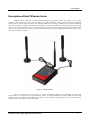
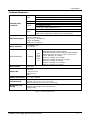
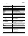
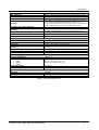
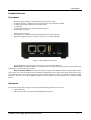
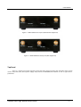


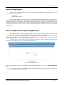
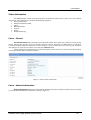
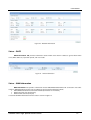
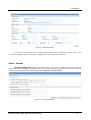
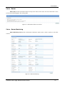
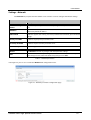
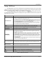
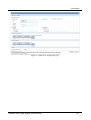
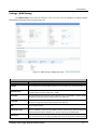
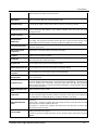
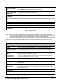
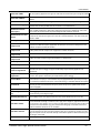
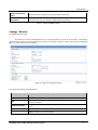
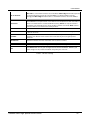
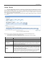
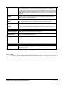
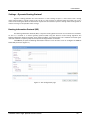
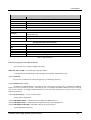
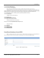

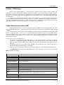
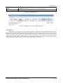
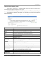
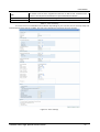
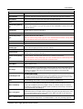
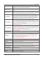
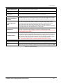
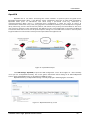
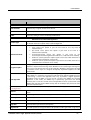

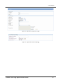
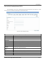
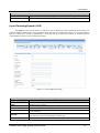
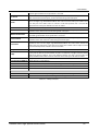
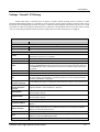
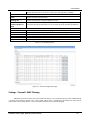
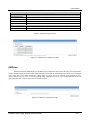
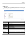

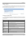
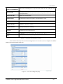
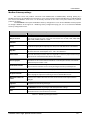
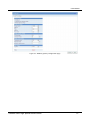
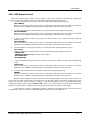
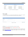
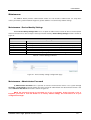
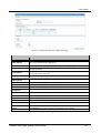
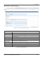
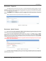
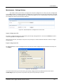
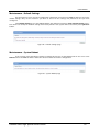
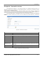
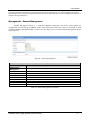
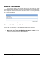
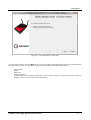
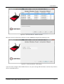
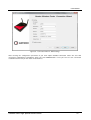
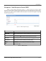
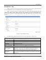
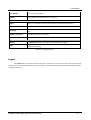
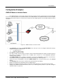
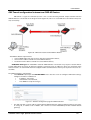
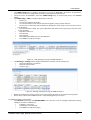
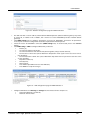
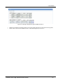
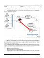
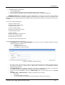
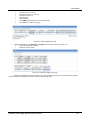
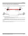
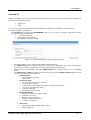
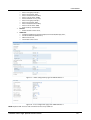
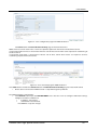
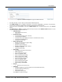
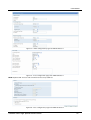
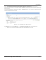
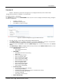
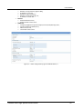
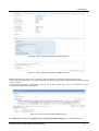
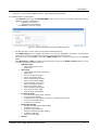
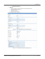
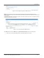
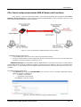
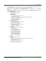
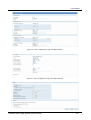
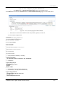
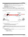
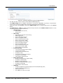
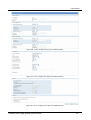
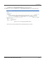
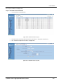
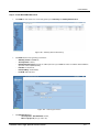
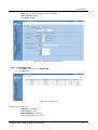
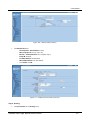
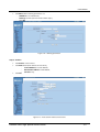
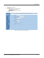
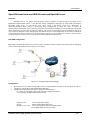
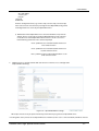
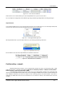
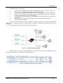
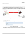
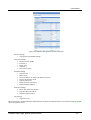

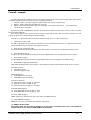
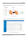
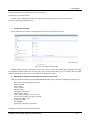
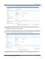
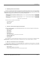
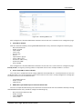
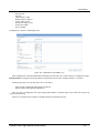
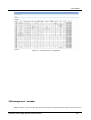
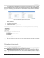
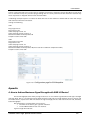


![[SANTIAGOLITEM.NET]](http://vs1.manualzilla.com/store/data/006051955_1-6793608479d1e718412b318dacd9cbdc-150x150.png)