1
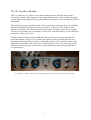
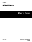
Oakley Sound Systems
3U Oakley Modular Series
Overdrive
Soft and hard clipping module
User Manual and Builder's Guide
V1.1.3
Tony Allgood B.Eng
Oakley Sound Systems
CARLISLE
United Kingdom
Introduction
This is the User Manual and Builder's Guide for the issue 1 Overdrive 3U module from
Oakley Sound.
This document contains a basic summary of its operation, a how it works section, a full parts
list for the components needed to populate the board and some basic testing methods.
For general information regarding where to get parts and suggested part numbers please see
our useful Parts Guide at the project webpage or http://www.oakleysound.com/parts.pdf.
For general information on how to build our modules, including circuit board population,
mounting front panel components and making up board interconnects please see our
Construction Guide at the project webpage or http://www.oakleysound.com/construct.pdf.
2
The 3U Overdrive Module
This is a simple but very effective waveform modifier module. It has two basic modes
selected by a switch. Hard clipping is a hard edged distortion type effect useful for grunging
up your signal. Soft clipping is a more subtle effect and produces a clean sounding overdriven
amp sound.
Three front panel pots control the sound. 'Gain' controls the overall gain of the 'pre-amplifier'
stage and essentially determines the level of overdrive or distortion. The 'timbre' or tone
control is an effective EQ control that affects the frequency response of the effected output.
The 'mix out' or balance pot is essentially a wet/dry mix control that allows you to add only as
much of the effect as you want.
Voltage control is determined not within this unit, but as part of the signal chain placed
before this module. Using a VCA to control the signal level that is fed into this unit will
determine the strength of the overdrive or distortion. Using a VCF to alter the timbre of the
signal fed to this module will control the overall harmonic level far more than using a filter
alone. In fact, hard sync type sounds can be easily obtained by simply sweeping the filter's
cut-off frequency.
The Oakley Overdrive module for the Eurorack format. This module has been built by Krisp1.
3
Using the Oakley Overdrive – A Personal Perspective.
Since this module has been available I have read many comments from users regarding its
usefulness. Probably more than any other Oakley module it has produced the largest split of
people who either loved, and still love it, and those that were profoundly disappointed with it.
Truthfully, I can't say I particularly enjoy receiving negative comments but in some ways it is
those negative comments that make one work harder to perfect any design. The problem is
that with some things it simply boils down to personal taste. I think the Oakley Overdrive is
one such thing – it either produces a sound that you like or it doesn't. Furthermore, since it
does very little other than overdrive the input signal it is a bit of a one trick pony. If you like
the trick then all is well, if not, it's time to move on.
Nevertheless, it may be that the module is somewhat misunderstood. After all, the most
common criticism with the module is that it doesn't actually do much. In this perspective I
wish to argue the case for its defence. It actually does do a lot but it all depends on what sort
of signal you are putting into it.
The Oakley Overdrive, in its overdrive mode, is quite simply a derivative of a famous
overdrive guitar pedal. This highly popular pedal has been around for many years and it is
widely copied. Several years ago I made up my own stomp box version of it. Initially, driven
from a 9V battery, then later from a 9V wallwart, I pretty much slavishly copied the original's
circuit. Later still I modified the main gain stage and then added a hard clipping circuit (the
distortion mode). I used this for many years with my SH-101 and SH-1 and it's pretty much
the plaintive solo sound on my own music albums.
The Oakley Overdrive module uses very similar circuitry to this prototype pedal. The basic
circuit topology remained the same but I changed the design to allow it to run from a split
power supply. I was careful to recreate the same voltage limits as in the 9V design as I was
keen to replicate the op-amp's saturated output characteristics. I also tailored the gain stages
to be more responsive to the levels seen in a modular synthesiser.
The key thing about using this module is to not use any signal that has a high harmonic
content. Indeed, inserting a raw square wave into it will do nothing. Overdriving a square
wave simply produces another square wave. The tone control may have an effect but it
probably won't lead to an increase in distortion. Inserting a sawtooth will also have little
effect. In fact it is more likely in this case that the sound is dulled – the sawtooth waveform
would be turned into something more square wave like and therefore less harmonics would
result. None of these things are perhaps what we would look for in a distortion unit.
Therefore to get the best out of the unit, when playing just single notes at one time, it is
important that the input signal should have a relatively low number of harmonics.
Where the Overdrive shines is when you use the module after a filter - especially one set to
relatively high resonance. The filter will select certain harmonics and the overdrive module
will accentuate these still further. So much so that the harmonic's frequency will dominate
over the fundamental. The effect is similar to the classic Moog Prodigy sync sound when
sweeping the frequency of a slaved VCO. And overdriving a simple one VCO - one VCF
arrangement is used frequently with the TB303 to give those rasping squealing acid lines.
4
However, it can be also used more subtly on more mellow filter sweeps with the overdrive
adding gentle overtones to a solo synthesiser lead.
The actual input level is very important too. The Overdrive module will produce much more
strident results when the input level approaches 5V peak. If the input signal is too weak then
the resultant overdriven effect will be much less. This means it is possible to get voltage
controlled overdrive effects if you use a VCA in front of the module.
It is traditional to have the distortion after the final VCA. In a fixed architecture synthesiser
this is generally the only way you can do it. But I find that using it between the VCF and the
final VCA gives me right sounds for solo work. The VCF will naturally vary the signal level
as the cut-off changes and having the VCA last will ensure that any additional hiss produced
by the high gain amplifier in the overdrive module will be only heard along with the signal
and therefore drowned out.
More complex sounds, such as chords, drum loops and so on, will be far more effected than
simple notes too. The more varying frequencies that are present in the input signal the more
distorted the output will appear. Generally speaking if you are after subtle overdriven effects
it is best to keep the input signal to just a few harmonically related notes.
5
The Overdrive PCB
The PCB has double sided copper traces and features though hole plating. The finish is Pbfree and the board is made from glass fibre for strength. The size of the board is 71mm (deep)
and 83mm (high).
I have provided space for the three main control pots on the PCB. If you use the specified
Alpha 16mm pots and matching brackets, the PCB can be held firmly to the panel without
any need for additional mounting procedures. The pot spacing is our standard for 3U
modules: 21mm.
The design requires plus and minus 12V or 15V supplies. The power supply should be
adequately regulated. The current consumption is about 15mA for each rail. Power is routed
onto the PCB by a four way 0.156” Molex/MTA type connector or 2 x 5-way 0.1” header.
The former is normally used by Frac based systems, as well as our own 5U MOTM
compatibles. The latter is found on most Euro modular systems. The four pins on the
Molex/MTA are +15V, ground, earth/panel ground, -15V. The earth connection allows you to
connect the metal front panel to the power supply’s ground without it sharing the modules’
ground line. More about this later.
As is common for our 3U series of modules the PCB has no mounting holes.
6
Components
For general information regarding where to get parts and suggested part numbers please see
our useful Parts Guide at the project webpage or http://www.oakleysound.com/parts.pdf.
Some special considerations for this project
The op amps are any high quality dual audio op-amp. The design has been tested with
OP275G, JRC4558, TL072 and OPA2134A. All parts work very well, but there are slight
audible differences in the part selected for U1. I will ask the builder to experiment here, but I
did like the results when using the OP275G in both U1 and U2. Use a socket for U1 and you
can swap chip types with ease.
The diodes are just ordinary 1N4148 silicon diodes. However, there is some scope in playing
around with the diode types in positions D1 and D2, and positions D3 and 4. Indeed, some
useful results can be obtained in using germanium diodes, like the OA91 or 1N34A, in
positions D1 and D3. This makes for asymmetrical distortion but I have not found the results
to be especially different in synthesiser use. You could also use two diodes in series for one
of the places, eg. D1 could be replaced by one 1N4148 and a 1N34A in series.
U3 and U4 are three terminal regulators. They are listed as 100mA devices and are +5V and
-5V respectively. They are very common devices – but be careful you don't get the surface
mount versions. You need the plastic TO-92 ones and not the SOP-8 package.
You will also need a PC mount horizontal double pole double throw switch. These are
sometimes called DPDT or 2PCO (two pole changeover). This type of switch has two sets of
contacts inside, each one has a wiper that can move between two other contacts. These sorts
of switches have six solder tags. Watch out for sizes, there are many different types of toggle
switches. The ones I recommend are Multicomp's part 1MD1T2B4M6RE which is available
from Farnell as part number 947-3270. Alternatively, Rapid sell a plastic bezelled one that
will fit, their part number: 75-0020.
7
3U Overdrive Parts List
The components are grouped into values, the order of the component names is of no
particular consequence.
A quick note on European part descriptions. R is shorthand for ohm. K is shorthand for kiloohm. For capacitors: 1uF = 1000nF. To prevent loss of the small ‘.’as the decimal point, a
convention of inserting the unit in its place is used. eg. 4R7 is a 4.7 ohm, 4K7 is a 4700 ohm
resistor, 6n8 is a 6.8 nF capacitor.
Resistors
5% 0.25W or better
47R
220R
1K
1K5
10K
15K
27K
33K
100K
360K
R15, R16
R5
R14, R2, R9
R4
R1
R10
R7
R3, R6, R11
R8, R13
R12
Capacitors
10pF, low K ceramic
47pF low-K ceramic
47nF polyester
150nF polyester
220nF polyester
470nF polyester
100nF multilayer ceramic
2u2, 63V electrolytic
C6, C17
C5
C15
C14
C1, C2
C9, C3, C4
C7, C8, C11, C12
C16, C10, C19, C20, C13, C18
Discrete Semiconductors
1N4148 silicon diode
D1, D2, D3, D4, D5, D6, D7, D8
Integrated Circuits
78L05 5V 100mA regulator
79L05 -5V 100mA regulator
OP275G dual op-amp
U3
U4
U1, U2
8
Onboard Pots
All pots Alpha 16mm
47K Lin or 50K Lin
100K Log
10K Lin
BALANCE
GAIN
TIMBRE
The TIMBRE and BALANCE pots have space to mount pot brackets.
Note that when fitting the GAIN pot, which has no pot bracket, a shim washer should be
fitted between the pot and the inside of the front panel. You can use the washer provided with
the pot for this purpose or get another one of similar size so that you can use the provided
washer on the outside like you would normally.
Wire link
Fit a small hoop of uninsulated wire (resistor lead clipping) into the two holes of LK. This
joins the two ground pins of the 4-way 0.156” header.
Miscellaneous
Leaded Ferrite beads
Double pole changeover switch
4-way 0.1” Molex/MTA header
L1, L2
SW1/2
SKT
And one of the following:
4-way 0.156” Molex/MTA header
2x5-way 0.1” header
PWR For +/-15V systems
PSU For +/-12V systems
3.5mm sockets
Two off mounted off board
You'll also need solder, two lots of about 75cm of insulated multistrand hook up wire, each of
a different colour, and a couple of cable ties.
You may well want to use sockets for the ICs. I would recommend low profile turned pin
types as these are the most reliable. You need two 8-pin DIL sockets.
9
Circuit Description
This module is probably one of the simplest we make, and indeed, if you have already looked
at other overdrive circuits you may well recognise some of the features used in this particular
design.
The module is powered in the conventional way from a split rail of +/-15V. This comes in to
the module via the 0.156” MTA connector PWR. L1 and L2 in conjunction with C16 and
C10 provide high frequency filtering and decoupling. They essentially act to keep the power
supply as free from noise as possible. The main overdrive and distortion circuitry is actually
run from a lower +/-5V supply. This is generated in the usual, if somewhat overkill, fashion
of using two three terminal regulators, U3 and U4. These generate a very stable quiet low
noise split 5V rail which the more sensitive parts of the overdrive circuitry can run. R15 and
C20, and their negative equivalent, provide additional filtering and isolation from main 15V
rails.
D5 to D8 provide discharge paths during power up and down cycles which could potentially
harm the ICs on the circuit.
The input signal is firstly attenuated by an inverting amplifier block based around U2A (pins
2, 3 and 1). This circuit reduces the input signal to around a quarter and provides the
following sections with a constant source impedance. Without this part of the circuit, the
overdrive core and the balance pot may affect the source signal's integrity and cause
unwanted distortion if you were using the Overdrive module in parallel with another module.
U2A's output is then split, one side going to the balance pot which will provide the 'dry'
signal, and the other side going into the overdrive's core circuitry.
The core of the overdrive module is based around the same circuit as used in many guitar
overdrive foot pedals. To my knowledge this type of design first appeared in the Ibanez
Tubescreamer TS-808 pedal, but it also appears in other commercial pedals including the
Boss OD-1 and SD-1, and other later Ibanez pedals. The TS-808 pedal has become something
like the equivalent of the TB-303 in the guitar world and the original green units sell for a
great deal of money. However, the basic circuit is actually quite simple and it is one that I
have used in various home made pedals for some time.
There are great deal of DIY TS-808 clones out there and many of them will talk about the
huge differences in using different diodes and types op-amps. I found that, for synthesiser use
at least, the actual sonic differences due to the actual devices used are not quite as obvious as
internet lore has decreed. However, I will leave it to the builder to experiment here and I am
sure that the Oakley Sound Forum would be a great place to discuss your findings.
The key in the basic TS overdrive circuit is the usage of a standard non-inverting high gain
op-amp stage, U3A, with two diodes in reverse parallel with the resistative feedback path.
These diodes act to limit the voltage across the feedback resistor. These are shown in the
schematic as D1 and D2. They can be switched in and out of the circuit with SW2, the
overdrive and distortion selection switch. Because they act upon the feedback voltage and not
the output signal directly they do not behave as a traditional clipping circuit. In the latter any
10
signal is simply limited to a set maximum or minimum voltage. The TS circuit is more subtle
than that.
The gain of the op-amp non-inverting amplifier is set by the resistances within the feedback
loop, but because of the way it works this is always more than or equal to one, ie.0dB. That
is, the output level is never less than the input. The exception to this is at very high
frequencies when the op-amp reaches its operating limits. Ignoring the diodes for now, U1A
has its passband gain set to a minimum of 11, via R2 and R1. The gain pot allows this gain to
increase still further by increasing the feedback resistance. With the gain pot turned up full
the maximum passband gain of the op-amp without the diodes is 111.
A diode will behave in such a way as to limit the positive voltage across it to no more than
0.6V. It does this by effectively changing its resistance depending on the voltage it has across
it. Two diodes connected in reverse parallel, head to tail, tail to head, will seek to limit the
voltage across them to +/-0.6V. D1 and D2 are connected to act like this.
So as the output level of U1A rises, either by turning up the gain pot or by applying a bigger
input signal, so does the feedback voltage. Once the feedback voltage gets to beyond +0.6V
or below -0.6V, the diodes start to conduct and the rise in output level is tempered. However,
the gain of U1A cannot fall to below unity, so the diodes only appear to act on the amplified
signal. Thus what we get at the output is a clipped amplified signal plus the original signal
superimposed on it. This is the TS sound and it has great tonal characteristics.
I ought to add that a great part of the overdrive sound is also due to frequency shaping. C2
rolls off the gain at lower frequencies. C5 and the slew rate of the op-amp act to curtail high
frequency components. It is these that set the width of passband, that area in which the opamp acts as an amplifier. In addition C9 will effectively block any DC signals to the
amplifier.
The Oakley Overdrive has a major difference that the original TS doesn't have. We can
switch out the diodes completely and allow U1A to become an unlimited high gain amplifier.
But of course, everything has limits and this time the output is limited by the supply voltage
to U1A. This is set by the +/-5V power supply and this causes the output to clip at around
+4V for positive excursions and -4V for the negative. The op-amp cannot produce any output
signal higher than this.
However, when SW2 switches out the two diodes in the feedback path, it also switches in, via
SW1, two more reverse parallel diodes, D3 and D4. In conjunction with current limiter R4,
these two diodes act as a traditional diode clipper and truncate the voltage across them to
around +/-0.6V. This is the 'distortion' mode and two different types of clipping are now
possible in this mode. The diode clipping is apparent with high input signals with low gain, or
low input signals with high gain. However, at high gains with medium to high input levels,
both the op-amp output limiting and diode clipping work together to give you a more
pronounced effect.
Immediately after the diode clipping circuit there is some additional high frequency filtering,
based around the actions of R4 and C14. This low pass filter reduces the harshness and gives
a rounded tone to the sound. Coupled with the bass end roll-off of C2, the overall frequency
response over the distortion sections is focussed on the mid-range part of the audio spectrum.
11
The tone control is based around the classic TS and SD-1 design and is built around U3B. Its
a simple circuit that works well in practice and produces enough tonal variation to be very
useful. At the lowest setting of the Tone pot, called 'timbre' on the suggested front panel, C1
acts in conjunction with R10 to produce a single pole low pass filter. At the high end of the
tone pot's travel, C1 now mostly acts in conjunction with the feedback resistor R9 and R5 and
produces a shelving high pass filter. This boosts high frequencies and produces a much
sharper sound. This is particularly apparent in the 'distortion' mode since this part of the
circuit produces much more higher harmonics due to the more severe clipping affect.
The output of the tone control stage is fed to the other end of the balance pot, called 'mix out'
on the front panel. This is a simple arrangement that lets the user apportion the mix of
distorted and straight-through signal. The relatively high impedance output of the wiper of
balance pot would not be able to drive any other external modules direct, so it is buffered and
amplified by a simple inverting amplifier U2B. R14 provides protection and stability for the
output signal.
12
Connections
This 3U module comes with two power supply possibilities.
1. Power connection PWR is the standard Oakley 4-way 0.156” MTA socket. Friction lock
types are recommended. This system is backward compatible with MOTM and Blacet
systems.
Power
Pin number
+15V
Module GND
Earth/panel metal
-15V
1
2
3
4
Note that the third pin is separate to the main module ground. This is the standard Oakley
power specification and allows for the front panel to be grounded to earth at the power
distribution board rather than locally through the module. However, other than in Oakley
modular systems it is not widely used. See comment about the wire link below.
2. Power connection PSU is the 10 pin Doepfer style power supply connection. This is a 2 x 5
0.1” header and will fit 0.1” flat ribbon IDC sockets. +12V goes to the top two pins of the
header, that is the ones nearest the legend PWR. It is imperative that the power be supplied
correctly. Damage to the module will result if the power supply is connected up the wrong
way.
For Fractional Rack and Euro sized systems please solder a small wire link into the board
where it is labelled LK. This connects the module ground and earth together and will make
the module behave the same way as your other modules.
For assembly into Oakley 5U and 3U complete systems you can omit the wire link.
All audio connections are via a four way 0.1” header on the PCB called 'SKT'. This may be
different to other Oakley PCBs you may have built. Doing it like this allows you to remove
the board from the front panel easily, and allows the potential for additional socket boards to
be used in any future production run of the board.
You don't have to use a header in your PCB, you can solder your wires directly to the PCB
from the various socket lugs if you wish.
If you have used the little Cliff sockets you will see that they have four connections. One is
the earth lug or ground tag. The second is the signal tag which will be connected to the tip of
the jack plug when it is inserted. The third and fourth tag are the normalised tags, or NC
(normally closed) lugs. The NC lugs are each internally connected to the ground and signal
tags when a jack plug is not inserted. These connections should be automatically broken
when you insert a jack. Pushing a jack plug into an unconnected socket and looking carefully
at the various contacts will reveal the actions of the NC lugs. In this module we have no need
for either of NC lugs.
13
Use multistrand hook up wire to connect each socket lug to the relevant pin on the header.
Keep your wires short but not too short and you can use as many different colour wires as you
can – although I tend to use one colour because I'm a minimalist. There is absolutely no need
to use screened cable for such short runs.
The connections of the lugs of the sockets that go directly to the PCB are summarised in the
table below.
Socket Name
Tag type
Header SKT Pin number
INPUT
INPUT
OUTPUT
OUTPUT
Signal
Earth
Signal
Earth
1 - the square one.
2
3
4
Once that is done, your module is ready for testing.
14
Testing, testing, 1, 2, 3...
Apply power to the unit making sure you are applying the power correctly. Check that no
device is running hot. Any sign of smoke or strange smells turn off the power immediately
and recheck the polarity of the power supply, and the direction of the ICs in their sockets and
the polarity of the electrolytic capacitors.
Assuming everything is OK so far, it is time to apply an audio input. The easiest way to test
the Overdrive module is to use a triangle wave output from a VCO. Start with the TIMBRE
pot set to its middle position, the gain pot at its lowest and the BALANCE pot to DRY. Set
the switch to OVERDRIVE. If you listen to the output signal you should hear just the triangle
wave as it would be if it were coming straight out of the VCO. Be careful to check your
listening levels as the output signal will get louder in the next section.
Now rotate the BALANCE pot and you should hear the sound becoming brighter. Now turn
up the GAIN and listen as the sound gets both louder and brighter still. Change the switch to
DISTORTION and the sound gets louder still and more harsh. There will a small click in the
audio output as the switch is moved, this is normal behaviour. Check that the GAIN pot still
has an effect on the sound with the switch in this position.
Alter the TIMBRE pot and you'll hear that this acts as a simple tone control – boosting treble
signals at its maximum level. You'll probably also notice that with a high gain setting that the
volume increases quite dramatically too as considerably more of the higher harmonics are let
through.
If all this happens, the chances are that you have a working module.
15
Final Comments
If you have any problems with the module, an excellent source of support is the Oakley
Sound Forum at Muffwiggler.com. Paul Darlow and I are on this group, as well as many
other users and builders of Oakley modules.
If you can't get your project to work, then Oakley Sound Systems are able to offer a 'get you
working' service. If you wish to take up this service please e-mail me, Tony Allgood, at my
contact e-mail address found on the website. I can service either fully populated PCBs or
whole modules. You will be charged for all postage costs, any parts used and my time at
25GBP per hour. Most faults can be found and fixed within one hour, and I normally return
modules within a week. The minimum charge is 25GBP plus return postage costs.
If you have a comment about this user guide, or have a found a mistake in it, then please do
let me know. But please do not contact me or Paul Darlow directly with questions about
sourcing components or general fault finding. Honestly, we would love to help but we do not
have the time to help everyone individually by e-mail.
Last but not least, can I say a big thank you to all of you who helped and inspired me. Thanks
especially to all those nice people on the Muffwiggler's forum and Synth-diy and Analogue
Heaven mailing lists.
Tony Allgood at Oakley Sound
Cumbria, UK
© October 2009 – updated July 2012
No part of this document may be copied by whatever means without my permission.
16