1
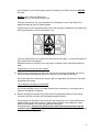
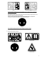
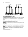
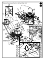
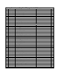
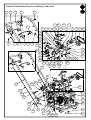
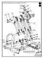
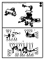
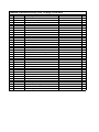
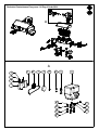
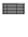
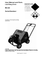
User Manual and Parts
List Easy Core
Model:
Serial Number:
Translation of the original operating
instructions
CAUTION:
FOR THE SAFE USE OF THE MACHINE AND FOR THE BEST RESULTS IT IS OF THE
UTMOST IMPORTANCE THAT YOU READ THIS USER MANUAL CAREFULLY BEFORE
USING THE EASY CORE.
0948 English 917.120.200
PREFACE
Congratulations with your Easy Core purchase. For the safe and prolonged operation of this
Easy Core, it is necessary to (have) read and understand this user manual.
Without the complete knowledge of the contents, you cannot operate this machine safely.
On the following page, the general safety instructions will be discussed first. Every user
should know and follow these. After this, a registration card is included, which should be
returned by mail, in order to be able to handle any future claims.
In this user manual, many instructions are in numerical order.
You should follow this order when taking any actions. Where the
indicates safety instructions. Where the
symbol appears, it
symbol is used, it indicates a hint and/or note.
GUARANTEE PROVISIONS
THIS EASY CORE IS SUPPLIED WITH A GUARANTEE AGAINST MATERIAL DEFECTS.
THIS GUARANTEE IS VALID FOR A PERIOD OF 12 MONTHS FROM THE DATE OF
PURCHASE.
EASY CORE GUARANTEES ARE SUBJECT TO THE “GENERAL CONDITIONS FOR
SUPPLY OF PLANT AND MACHINERY FOR EXPORT, NUMBER 188”, WHICH ARE
PUBLISHED UNDER THE AUSPICES OF THE UNITED NATIONS ECONOMIC
COMMISSION FOR EUROPE.
All information and technical specifications provided at the moment that this document is
published are the most recent ones. Design specifications may be changed without prior
notice.
This document is a translation of the original operating instructions.
Upon request, the original operating instructions are available in Dutch.
REGISTRATION CARD
Please fill in the form below for your own reference:
Serial number of machine
Dealer name
Purchase date
Remarks
2
!
Fig.1
SAFETY REGULATIONS
!
The Easy Core is designed for safe use. This is only
possible if the safety instructions as described in this
manual are observed in full.
Please read and understand (Fig.1) the manual before you
start using the Easy Core.
If the machine is not used, as described in the manual,
personal injury and/or damage to the Easy Core may
occur.
1) When using the machine, the operator should be skilled.
The manufacturer does not accept any responsibility for incompetent use and the
damage resulting from this; all risks that occur under such circumstances are the sole
responsibility of the user.
Incompetent use also includes not following the instructions for use, maintenance and
repair as prescribed by the manufacturer.
Before using the Easy Core, please inspect the area to be treated.
Remove loose obstacles and avoid irregularities.
2) The Easy Core is manufactured in accordance with the latest technological
knowledge, and can be used safely.
If the machine is used, maintained or repaired by incompetent persons, injury to both
the user and third parties may occur.
This should be avoided!
3) Any person appointed by the owner to operate, maintain or repair the Easy Core must
have read and fully understood the user manual and especially the Chapter Safety
Regulations.
The user is responsible for the safe use of the Easy Core.
4) The user is obliged to check for any visible damage or defects, before he/ she
uses the Easy Core.
Modifications to the Easy Core (including its operation) that adversely affect the
safety must be immediately remedied.
Any modifications or additions to the Easy Core (except for those approved by the
manufacturer) are in principle prohibited because of safety considerations.
If modifications have been carried out to the Easy Core, the current CE marking will
no longer be valid, and the person who carried out the modifications must personally
take care of a new CE marking.
Check the Easy Core, before every operation, for loose bolts/ nuts/ parts.
If present, regularly check the hydraulic hoses and replace them if they are damaged
or show signs of ageing. The replacement hoses must comply with the technical
requirements of the manufacturer.
If present, the hydraulic unit must always be made pressure-free, before activities are
carried out on it.
3
If the protective covers and safety stickers are absent, the Easy Core must NEVER
be used.
NEVER crawl under the Easy Core.
If necessary, you can tilt the Easy Core.
During maintenance, set up and repairs it is necessary to secure the Easy Core
against sinking/ driving off/ slipping away.
Always switch off the engine and disconnect the spark plug cable from the spark plug
during maintenance, set up and repairs. (Fig.2)
Fig.2
Only use original Easy Core parts for maintenance and repair, to ensure the safety of
the machine and the operator.
Repair activities on the Easy Core may only be carried out by authorised technical
staff.
Please keep a summary of the repairs.
5) Apart from the instructions in this user manual, the generally applicable, as well as
the Occupational Health and Safety Act, provisions must also be obeyed.
When the machine is used on the public road, the applicable provisions of the traffic
regulations also apply.
The transport of people is not allowed!
Do not use the Easy Core in the dark, during heavy rain/storm or on slopes with a
gradient exceeding 15 degrees.
6) Before starting the activities, all persons who will operate the Easy Core must be
informed of all the functions and operating elements thereof.
On both sides of the Easy Core and on the rear and front cover, safety stickers are
attached with an identical meaning. These safety stickers must always be clearly
visible and readable, and must be replaced if damaged.
During operation, NO persons without the proper personal protection may be
present in the danger area of the Easy Core, since there is danger of personal injury
resulting from moving parts. (Fig.4)
4
Fig.4
Fig.5
For bystanders without personal protective gear: please keep a minimum
distance of 4 metres! (Fig.5)
Be dressed correctly. Wear sturdy shoes with a steel toecap, long trousers, tie up
long hair, and do not wear loose clothing.
Use the correct personal protective gear in accordance with the applicable
Occupational Health and Safety Act and safety provisions.
Fig.6
Use certified hearing protection when using the machine! (Fig.6)
7) Safety and indication stickers
900.280.402
911.280.402
911.340.410
900.280.404
5
917.340.402
917.340.400
917.340.404 (208 only)
917.340.408 (208 only)
917.340.406 (208 only)
Description of stickers
917.260.410
Model sticker Easy Core 104
917.260.412
Model sticker Easy Core 106
917.260.414
Model sticker Easy Core 108
917.260.416
Model sticker Easy Core 116
917.260.418
Model sticker Easy Core 208
911.280.402
Safety sticker concerning the use of machine
900.280.402
Safety sticker concerning reading the manual
911.340.410
Safety sticker concerning wearing hearing protection
900.280.404
Safety sticker in order to prevent crushed fingers
917.340.400
Warning to lift the cover straight up in order to avoid back injuries
917.340.402
Operating handle to turn on the pins
917.340.404
Operating handle for forward movement / pins up
917.340.406
Operating handle to turn on the pins
917.340.408
Hydrostat switch
6
TABLE OF CONTENTS
PREFACE ..................................................................................................................... 2
GUARANTEE PROVISIONS ......................................................................................... 2
REGISTRATION CARD................................................................................................. 2
SAFETY REGULATIONS ............................................................................................. 3
1.0 TECHNICAL DATA........................................................................................................ 8
2.0 ASSEMBLY INSTRUCTIONS........................................................................................ 9
3.0 USER MANUAL............................................................................................................10
4.0 EU DECLARATION ......................................................................................................11
5.0 MAINTENANCE ...........................................................................................................12
7
1.0
TECHNICAL DATA
Model
104
106
108
208
116
Engine
BUS
5.5 HP
360 mm
(14.2”)
70 mm
(2 3/4”)
90 x 150 mm
(3 5/8” x 6”)
2043 m2/h
(21990 ft2/h)
Honda
5 HP
540 mm
(21.3”)
70 mm
(2 3/4”)
90 x 150 mm
(3 5/8” x 6”)
2550 m2/h
(27448 ft2/h)
Honda
5 HP
520 mm
(20.5”)
70 mm
(2 3/4”)
65 x 170 mm
(2 1/4” x 7”)
2550 m2/h
(27448 ft2/h)
Honda
5.5 HP
520 mm
(20.5”)
70 mm
(2 3/4”)
65 x 170 mm
(2 1/4” x 7”)
2780 m2/h
(29924 ft2/h)
Kohler
12 HP
1,100 mm
(43.3”)
70 mm
(2 3/4”)
65 x 170 mm
(2 1/4” x 7”)
7800 m2/h
(83959 ft2/h)
4
6
8
8
16
22 x 16 x 70
mm
(7/8” x 5/8” x
2 3/4”)
16 x 9.5 x 70
mm
(5/8” x 3/8” x
2 3/4”)
9.5 x 70 mm
(3/8” x 2
3/4”)
22 x 70 mm
(7/8” x 2
3/4”)
22 x 16 x 70
mm
(7/8” x 5/8” x
2 3/4”)
16 x 9.5 x 70
mm
(5/8” x 3/8” x
2 3/4”)
9.5 x 70 mm
(3/8” x 2
3/4”)
22 x 70 mm
(7/8” x 2
3/4”)
22 x 16 x 70
mm
(7/8” x 5/8” x
2 3/4”)
16 x 9.5 x 70
mm
(5/8” x 3/8” x
2 3/4”)
9.5 x 70 mm
(3/8” x 2
3/4”)
22 x 70 mm
(7/8” x 2
3/4”)
22 x 16 x 70
mm
(7/8” x 5/8” x
2 3/4”)
16 x 9.5 x 70
mm
(5/8” x 3/8” x
2 3/4”)
9.5 x 70 mm
(3/8” x 2
3/4”)
22 x 70 mm
(7/8” x 2
3/4”)
22 x 16 x 70
mm
(7/8” x 5/8” x
2 3/4”)
16 x 9.5 x 70
mm
(5/8” x 3/8” x
2 3/4”)
9.5 x 70 mm
(3/8” x 2
3/4”)
22 x 70 mm
(7/8” x 2
3/4”)
1600 x 620 x
950 mm
(63” x 24.4” x
37.4”)
94 kg
(207 lbs)
1300 x 660 x
960 mm
(51.2” x 26” x
37.8”)
115 kg
(254 lbs)
SAE 30
No
1600 x 800 x
950 mm
(63” x 31.5” x
37.4”)
113 kg
(249 lbs)
1080 x 800 x
680 mm
(42.5” x 31.5”
x 26.8)
135 kg
(298 lbs)
SAE 30
No
1600 x 800 x
950 mm
(63” x 31.5” x
37.4”)
136 kg
(300 lbs)
1080 x 800 x
680 mm
(42.5” x 31.5”
x 26.8)
145 kg
(320 lbs)
SAE 30
No
850 x 1700 x
950 mm
(33.5” x 67” x
37.4”)
146 kg
(322 lbs)
1260 x 1050
x 890 mm
(49.6 x 41.3”
x 35”)
162 kg
(357 lbs)
SAE 30
Yes
1700 x 1440
x 850 mm
(67” x 56.7” x
33.5”)
326 kg
(719 lbs)
1600 x 1350
x 1,000 mm
(63” x 53.1” x
39.4”)
367 kg
(809 lbs)
SAE 30
No
Operating
width
Operating
depth, up to
Hole distance
Capacity, up
to
Number of
pins
Standard
hollow pin
Optional
hollow pin
Optional
massive pins
Operating
dimensions
Weight
Shipping
dimensions
Shipping
weight
Engine oil
footboard
8
2.0
ASSEMBLY INSTRUCTIONS
Assembly of Easy Core 104
Operating handle: The foldaway operating handle has already been mounted in advance. In
order to use the machine, the handle must be turned to the rear. To do this, you first pull
back the handle retainer, and turn the handle backwards. Then you push the retainer back so
that the operating handle is in a locked position. Apply this method in reverse order in order
to bring the operating handle back to the transport position.
Assembly of Easy Core 106 and 108; please refer to Figure at point 3.0 user manual
Operating handle: Push the operating handle over the two projecting frame pins. The
control handle should now point upwards. Mount the locking pins and secure them with the
two locking clamps, or in whatever way the handle is mounted and secured.
Pullback cable: Massive steel wire with identical ends, mounted on one side of the black
pullback plate. This has already been mounted in advance. On the other end, the cable
should be mounted to the central handle (no. 1). Mount the cable by means of the locking pin
and locking clamp.
Coupler flange: Massive rod with a yoke on one end. Remove the cover from the machine
and localise the yoke on the machine at the bottom right. Turn the rod into the yoke, up to the
adjustment nut (note: thread is left, so the rod must be turned counter-clockwise). Attach the
yoke end of the rod to the lower handle (no. 2) using the supplied locking pin and locking
clamp. Both yokes must now be secured with both of the adjustment nuts.
Assembly of Easy Core 208
Operating handle: Push the operating handle over the two projecting frame pins. The
control handle should now point upwards. Mount the locking pins and secure them with the
two locking clamps, or in whatever way the handle is mounted and secured.
Hydrostat control: The left handle (no. 3) operates the hydrostat. Remove the split pin,
mount the cable's ball joint, and attach the split pin again. Mount the outer cable's nuts on the
operating handle.
Pullback cable: Massive steel wire with identical ends, mounted on one side of the black
pullback plate. This has already been mounted in advance. On the other end, the cable
should be mounted to the central handle (no. 1). Mount the cable using the locking pin and
split pin.
Coupler flange: Massive rod with a ball joint on one end. Remove the cover from the
machine and localise the ball on the machine at the bottom right. Mount the ball joint, in the
bottom right of the machine, to the ball. Mount the other end of the rod to handle no. 4 and
secure it with the split pin.
Hydrostat: The hydrostat was fully inspected and checked, and is ready for use. The handle
on the front of the machine, marked as “Hydrostat Bypass”, should be switched down, in
enable the use of the hydrostat.
9
3.0
USER MANUAL
1
2
3
1
4
User manual Easy Core 104, 106, 108, and 208
Lower handle: The lower handle (2) operates the idler for the drive V-belts. Pull the handle
up to switch on. The handle should be kept pulled up to operate the machine. If it is released,
the forward motion will stop. If the handle does not shoot back, when released, please
contact the manufacturer or the dealer to remedy this, since it is very important for your
safety.
Central handle: The central handle (1) ensures that the aeration mechanism of the Easy
Core is moved forward into operating position. Move the handle forward. The aeration
mechanism will automatically place itself in the correct position.
Aerating: Pull the lower handle (2) up and keep it tight. Then move the central handle (1)
forward and let the aeration mechanism move itself into the operating position. Do not push
the machine as soon as it starts operating; due to the movement of the pins it will start to
drive forwards.
With the Easy Core 208, the right handle (4) ensures that the drive for the V-belts is switched
on. During aeration, the machine is moved forwards hydraulically by operating the left handle
(3). To stop the aeration, you release both handles (3 & 4).
Stop: Release the lower handle, to stop. It will automatically shoot back and switch off the
idler. Pull back the central handle to pull the aeration mechanism out of the soil. Switch off
the engine, if the machine is not be used any more.
Removing the cover: To remove the cover, the central bolt and rubber hoses must be
removed. To mount the cover again, you should follow the same procedure in the reverse
order.
Use under cold conditions: Switch the aeration mechanism to the “upward” position for at
least two minutes, to warm the grease.
10
User manual for Easy Core 116
•
•
•
•
•
•
•
•
•
•
•
•
•
4.0
Adjust the length of the draw hook so that the pulling vehicle does not touch the
machine when turning corners.
Install the control box on the respective vehicle, in a location where it can be operated
easily.
Ensure that the wire cannot become stuck somewhere or stretch during use.
Start the engine and turn at full speed.
Drive to the desired location to be aerated, with the Easy Core in the upright position.
Lower the machine until it cannot be lowered any further.
The pulling vehicle must be moving forwards before the aeration mechanism can be
switched on.
After this, start driving forwards at a speed between 3-5 km/h (2-3 mph).
Switch on the aeration mechanism and adjust the speed, so the green light is on
continuously.
Slow down if the red “fast” light is on.
Increase the speed if the red “slow” light is on, (this results in damage to the Easy
Core and soil)
It is possible to make gradual turns during the aeration process.
Switch off the aeration mechanism and lift it from the soil when making sharp turns.
EU DECLARATION
The product:
EASY CORE WITH MACHINE NUMBER AS INDICATED ON THE MACHINE AS WELL AS
IN THIS MANUAL,
to which this declaration relates is according to the stipulation of the 2006/42/EC directive for
machines.
Zeist, 01/10/09
A.C. Bos
Manager Operations & Logistics
Redexim Holland
11
5.0
MAINTENANCE
Model
Time frame
all
models
104
106
108
Before each operation
After each 10 hours of
operation
After every 100 hours of
operation or annually
Check point / lubricating
point
Method
engine/oil filter
Please follow the
instructions from the
engine manufacturer,
however, change oil
and/or filters at least
once a year
- Check for loose bolts /
nuts
- Tighten the loose
bolts / nuts
- Presence and readability
of the safety stickers
- Check the tension of the
V-belt
- Replace them if not
present / damaged
- Adjust the tension of
the V-belt if
necessary
- Tighten the loose
bolts / nuts
- 2 shots of EP2
- Tighten the loose
bolts / nuts
- Replace these parts if
necessary
- Adjust the tension of
the V-belt if
necessary
- Or replace the V-belt
if necessary
- 2 shots of EP2
- Check for loose bolts /
nuts
- Lubricate cam bearings
- Check for loose bolts /
nuts
- Check the roll bearings
and the drive line
- Check the tension / wear
of the V-belt
- Lubricate spindle and
wheel bearings
208
Before each operation
After every 10 hours of
operation
After every 20 hours of
operation
- Check for loose bolts /
nuts
- Existence and readability
of the safety stickers
- Check the tension of the
V-belts
- Tighten the loose
bolts / nuts
- Replace them, if not
present or damaged
- Adjust the tension of
the V-belts if
necessary
- Check for loose bolts /
nuts
- Lubricate cam bearings
- Tighten the loose
bolts / nuts
- 2 shots of EP2
- Lubricate the bearings of
the hydrostatic drive.
These are located next to
the coupling belts
- Lubricate front wheel
spindle
- 2 shots of EP2
- 2 shots of EP2
12
After every 100 hours of
operation or annually
- Check for loose bolts /
nuts
- Check the roll bearings
and the drive line
- Check the tension / wear
of the V-belts
- Lubricate spindle and
wheel bearings
116
- Tighten the loose
bolts / nuts
- Replace these parts if
necessary
- Adjust the tension of
the
V-belts if necessary
- Or replace the V-belts
if necessary
- 2 shots of EP2
Before each operation
- Check for loose bolts /
nuts
- Existence and readability
of the safety stickers
- Tighten the loose
bolts / nuts
- Replace them, if not
present or damaged
After every 10 hours of
operation
- Check the roll bearings
and the drive line
- Check the tension of the
chain
- Check for loose bolts /
nuts
- Lubricate cam bearings
- Check for loose bolts /
nuts
- Check the roll bearings
and the drive line
- Check the tension / wear
of the chain
- Replace these parts if
necessary
- Adjust the tension of
the chain if necessary
- Tighten the loose
bolts / nuts
- 2 shots of EP2
- Tighten the loose
bolts / nuts
- Replace these parts if
necessary
- Adjust the tension of
the chain if necessary
- Or replace the chain if
necessary
- Use a universal chain
grease
- 2 shots of EP2
After every 100 hours of
operation or annually
- Lubricate chain
- Lubricate spindle and
wheel bearings
GENERAL REMARKS ON MAINTENANCE
Tightening the V-belts: Tighten the V-belts by using the adjustment holes inside the rotating
handle of the coupling. It should only be necessary to move it to the next hole. Do not over
tighten the belts. This could result in a too great a load on the engine's spindle bearings. The
V-belts are sufficiently tight when they do not slip during the operating cycle.
Tightening the chain (Easy Core 116 only): Tighten the chain tension by using the holes
inside the engine plate. Do not over tighten the chain. This could result in a too great a load
on the engine's gearbox bearings. The chain is tight enough if it is not slack during the
operating cycle.
Pins: These are adjustable, but the maximum adjustment course is the thickness of the
adjustment nut, around 6.5 mm (1/4”). The openings of the pins must always be pointed to
the rear of the machine. The pins can be replaced by loosening the adjustment nut and
subsequently loosening the pin. Now mount the new pin with the adjustment nut. Mount the
pin, by as many thread windings as possible, into the pin holder. Now tighten the adjustment
nut against the pin holder.
For the maintenance of the engine, see the supplied manual of the engine.
13
Redexim-Charterhouse Easy Core 104 Pag 1 Code 0912
1
2
5
3
9
4
4
10
6
7
8
15
14
13
12
16
11
10
36
18
26
27
27
26
23
5
17
22
21
20
19
20
18
28
29
24
25
30
18
19
31
31
32
33
34
35
Redexim-Charterhouse Easy Core 104 page1 code 0912
1
2
3
4
5
6
7
8
9
9
10
10
11
12
13
14
15
16
17
18
19
20
21
22
23
24
25
26
27
28
29
30
31
32
33
34
35
36
Part #
E91.929.091
E91.939.495
E91.909.391
E91.919.598
E91.909.899
E91.919.393
E91.929.494
E91.919.595
E91.919.29B
E91.919.29H
E91.909.79B
E91.909.79H
E91.919.196
E91.919.194
E91.919.299
E91.919.193
E91.919.296
E91.919.390
E91.919.493
E91.909.195
E91.909.196
E91.919.190
E91.909.699
E91.919.099
E91.919.293
E91.909.198
E91.909.793
E91.919.699
E91.959.293
E91.919.794
E91.909.498
E91.909.997
E91.909.991
E91.909.299
E91.919.793
E91.909.093
E91.919.195
E91.929.498
DESCRIPTION
Retractor Handle
Clevis Pin, 1/4 x 1"
Cotter Pin, 1/16 dia x 3/4"
Shoulder Bolt, 5/16 dia x 1/4"
Control Cable Assembly
Cover
Lock Nut, 1/4-20 UNC
Cover Screw, 1/4-20 SHCS
CE Required Muffler Guard B$S
CE Required Muffler Guard Honda
Engine, Briggs & Stratton 5.5HP
Engine Honda 5HP
Vibration Dampener
Lock Nut, 10-24 UNC
Safety Switch
Button Head Screw,10-24 UNC x 3/4"
Wiring Harness
Shutoff Switch Bracket
Hex Head Bolt, 5/16-18 UNC x 1 1/2"
Flat Washer, 5/16"
Lock Nut, 5/16-18 UNC
Lock Nut, 5/8-11 UNC
Wheel w/ Grease Fittings
Hex Head Bolt, 5/8-11 UNC x 4 1/2"
Key
Pulley, Engine
V-Belt, Cogged, 38"
Pivot Bushing
Cotter Pin 1/8" dia x 1"
Pivot Bracket L.H.
Hex bolt, 1/4-20 UNC - 1 1/2"
Retractor Plate
Flat Washer 1/4"
Lock Nut, 1/4 x 20 UNC
Pivot Bracket R.H.
Rubber Latch Kit
Stainless Rivet, 1/8 dia x 1/4"
Hex head bolt, 5/16 - 18 UNC x 1 3/4
REMARKS
QUA
1
1
1
2
1
1
2
1
1
1
1
1
4
2
1
2
1
1
4
16
8
4
4
4
1
1
1
2
2
1
1
1
2
1
1
2
4
4
Redexim-Charterhouse Easy Core 104 Pag 2 Code 0912
5
2
4
13
3
8
6
7
1
1
7
3
4
2
10
16
9
11
3
14
15
12
17
13
8
22
18
19
20
19
21
25
17
26
27
3
23
24
Redexim-Charterhouse Easy Core 104 page 2 code 0912
1
2
3
4
5
6
7
8
9
10
11
12
13
14
15
16
17
18
19
20
21
22
23
24
25
26
27
PART #
E91.909.492
E91.959.296
E91.909.495
E91.929.996
E91.909.592
E91.919.796
E91.919.797
E91.909.494
E91.919.795
E91.909.691
E91.909.597
E91.919.499
E91.919.590
E91.919.591
E91.919.592
E91.919.392
E91.919.492
E91.919.491
E91.929.897
E91.929.894
E91.919.490
E91.909.294
E91.909.992
E91.909.292
E91.919.397
E91.909.797
E91.919.395
E91.919.298
E91.909.391
E91.919.398
E91.909.196
DESCRIPTION
Cartridge Bearing
Bearing Spacer
Lock Nut, 3/8-16 UNC
Crankshaft
Grease Fitting
Tine Rod Cap
Journal Bearing
Flat Washer, 3/8"
Tine Rod
Hex Jam Nut, 5/8-18 UNF
Standard Hollow Tine, 5/8" (22x16x70 mm)
Optional Solid Tine, 7/8" (22x70 mm)
Optional Hollow Tine, 3/8" (16x9,5x70 mm)
Optional Solid Tine, 3/8" (9,5x70 mm)
Optional Hollow Tine, 1 1/2" (45x38x70 mm)
Frame w/o Handle
Hex Head Bolt, 3/8-16 UNC x 2"
Shoulder Bolt, 5/16-18 UNC x 1 3/8"
Clutch Control Bar
Handle
Clutch Cable Assembly
Hex Head Bolt, 1/2-13 UNC x 2"
1/2" Machine Bushing
Pulley, Clutch
Clutch Bracket
Clevis Pin, 1/4 x 3/4 "
Lock Collar
Hex Head Bolt, 3/8-16 UNC x 1 3/4"
Cotter Pin, 1/16 dia x 3/4"
Torsion Spring
Lock Nut, 5/16-18 UNC
REMARKS
QUA
2
2
14
1
4
4
8
12
4
4
4
4
4
4
4
1
12
1
1
1
1
1
2
1
1
1
2
2
1
1
8
Redexim-Charterhouse Easycore 106 Pag 1 Code 0912
1
4
2
3
5
6
7
12
11
13
8
14
9
15
10
16
25
21
22
23
24
20
17
18
19
27
28
8
28
27
29
32
33
31
30
26
Redexim-Charterhouse Easy Core 106 page 1 code 0912
1
2
3
4
5
6
7
8
9
10
11
12
13
14
15
16
17
18
19
20
21
22
23
24
25
26
27
28
29
30
31
32
33
PART #
E91.929.091
E91.909.391
E91.939.495
E91.919.598
E91.919.494
E91.919.198
E91.919.595
E91.909.899
E91.919.193
E91.919.196
E91.919.299
E91.919.194
E91.919.290
E91.919.390
E91.919.29H
E91.909.79H
E91.919.293
E91.919.099
E91.909.699
E91.919.190
E91.909.792
E91.909.195
E91.929.498
E91.909.498
E91.909.093
E91.919.195
E91.909.691
E91.909.693
E91.909.991
E91.909.299
E91.909.995
E91.909.198
E91.909.793
DESCRIPTION
Retractor Handle
Cotter Pin, 1/16 dia x 3/4"
Clevis Pin, 1/4 x 1"
Shoulder Bolt, 5/16 dia x 1/4
Lock Nut, 1/4-20 UNC
Cover
Cover Screw, 1/4-20 SHCS x 1 3/4"
Control Cable Assembly
Button Head Screw, 10-24 UNC x 3/4"
Vibration Dampener
Safety Switch
Lock Nut, 10-24 UNC
Wiring Harness
Shut-Off Switch Bracket
CE Required Muffler Guard
Engine, Honda 5.5HP OHV
Key
Hex Head Bolt, 5/8-11 UNC x 4 1/2"
Wheel w/ Grease Fitting
Lock Nut, 5/8-11 UNC
Lock Nut, 5/16-18 UNC
Flat Washer, 5/16"
Hex Head Bolt, 5/16 - 18 UNC x 1 3/4"
Hex bolt, 1/4-20 UNC - 1 1/2"
Rubber Latch Kit
Stainless Rivet 1/8 dia x 1/4"
Hex Jam Nut, 5/8-18 UNF
Flat Washer, 5/8"
Flat washer, 1/4
*Varies*
Retractor Plate
Pulley, Engine
V-Belt, Cogged
REMARKS
QUA
1
1
1
3
2
1
1
1
2
4
1
2
1
1
1
1
1
4
4
4
5
8
4
1
2
4
4
4
3
1
1
2
2
Redexim-Charterhouse Easycore 106 Pag 2 Code 0912
1
5
2
10
3
7
4
8
5
9
6
11
14
8
13
20
21
12
20
13
16
19
12
18
17
40
39
14
15
22
32
35
42
41
23
24
26
27
31
25
28
29
30
40
35
32
32
37
33
4
38
43
36
33
33
34
42
38
Redexim-Charterhouse Easy Core 106 page 2 code 0912
1
2
3
4
5
6
7
8
9
10
11
12
13
14
15
16
17
18
19
20
21
22
23
24
25
26
27
28
29
30
31
32
33
34
35
36
37
38
39
40
41
42
43
PART #
E91.909.593
E91.909.591
E91.919.892
E91.909.299
E91.909.499
E91.909.690
E91.909.498
E91.909.592
E91.909.590
E91.909.594
E91.909.994
E91.909.599
E91.909.495
E91.909.492
E91.919.295
E91.909.691
E91.909.692
E91.909.597
E91.919.499
E91.919.590
E91.919.591
E91.919.592
E91.909.596
E91.909.497
E91.909.993
E91.909.698
E91.919.492
E91.909.494
E91.909.798
E91.909.799
E91.909.992
E91.919.397
E91.909.792
E91.919.398
E91.919.491
E91.919.095
E91.909.391
E91.919.596
E91.919.096
E91.919.593
E91.919.598
E91.909.797
E91.929.896
E91.929.899
E91.929.395
E91.939.499
E91.929.394
DESCRIPTION
Cam Bearing
Cam, Machined
Split Lock Washer, 1/4"
*Varies*
Cam Alignment Plate
Hanger Rod Bearing w/ Bushing
Hex Head Bolt, 1/4-20 UNC x 1 1/2"
Grease Fitting
Tine Casting
Woodruff Key
Drive Shaft
Spacer, Long
Lock Nut, 3/8-16 UNC
Cartridge Bearing
Spacer Short
Hex Jam Nut, 5/8-18 UNF
Hanger Rod
Standard Hollow Tine, 5/8" (22x16x70 mm)
Optional Solid Tine, 7/8" (22x70 mm)
Optional Hollow Tine, 3/8" (16x9,5x70 mm)
Optional Solid Tine, 3/8" (9,5x70 mm)
Optional Hollow Tine, 1 1/2" (45x38x70 mm)
Hex Jam Nut, 5/8-11 UNC
Spacer Washer
Pulley, Crank Shaft
Frame w/o Handle
Hex Head Bolt, 3/8-16 UNC x 2"
Flat Washer, 3/8"
Hex Head Bolt, 1/2-13 UNC x 2 1/2"
Pulley, Clutch
1/2" Machine Bushing
Clutch Bracket
Lock Nut, 5/16-18 UNC
Torsion Spring
Shoulder Bolt, 3/8-16 UNC x 1 3/8"
Clevis Pin 3/16 dia x 1 1/4"
Cotter Pin, 1/16 dia x 3/4"
Clutch Linkage
Hair Pin
Pivot Plate
Shoulder Bolt, 5/16 dia x 1/4
Clevis Pin, 1/4 x 3/4"
Handle
Clutch Control Bar
Clevis Fitting, L.H.
Clutch Handle Linkage
Clevis Fitting, R.H.
REMARKS
QUA
6
6
18
19
12
2
18
8
6
7
1
5
4
2
1
6
2
6
6
6
6
6
6
3
1
1
4
4
1
2
1
1
5
1
1
2
4
1
2
1
1
2
1
1
1
1
1
Redexim-Charterhouse Easy Core 108 Pag 1 Code 0912
1
5
9
2
10
6
35
3
13
12
31
4
14
3
8
7
10
19
20
17
15
21
22
18
35
12
31
16
25
4
24
26
27
28
23
11
36
12
34
31
37
30
32
33
Redexim-Charterhouse Easy Core 108 page 1 code 0912
1
2
3
4
5
6
7
8
9
10
11
12
13
14
15
16
17
18
19
20
21
22
23
24
25
26
27
28
29
30
31
32
33
34
35
36
37
PART #
E91.929.091
E91.939.495
E91.929.494
E91.909.899
E91.909.391
E91.919.598
E91.919.595
E91.919.198
E91.919.794
E91.919.699
E91.919.493
E91.909.195
E91.919.29H
E91.909.79H
E91.959.293
E91.919.793
E91.919.193
E91.919.196
E91.919.299
E91.919.194
E91.919.290
E91.919.390
E91.919.190
E91.919.099
E91.909.699
E91.919.195
E91.909.093
E91.919.293
E91.909.799
E91.909.793
E91.909.792
E91.919.497
E91.909.299
E91.909.991
E91.929.498
E91.909.498
E91.909.198
DESCRIPTION
Retractor Handle
Clevis Pin, 1/4 x 1"
Lock Nut, 1/4-20 UNC
Control Cable Assembly
Cotter Pin, 1/16 dia x 3/4"
Shoulder Bolt, 5/16 dia x 1/4"
Cover Screw, 1/4-20 SHCS
Cover
Pivot Bracket L.H.
Pivot Bushing
Hex Head Bolt, 5/16-18 UNC x 1 1/2"
Flat Washer, 5/16"
CE Required Muffler Guard
Engine, Honda 5.5HP OHV
Cotter Pin 1/8" dia x 1"
Pivot Bracket R.H.
Button Head Screw, 10-24 UNC x 3/4"
Vibration Dampener
Safety Switch
Lock Nut, 10-24 UNC
Wiring Harness
Shut-Off Switch Bracket
Lock Nut, 5/8-11 UNC
Hex Head Bolt, 5/8-11 UNC x 4 1/2"
Wheel w/ Grease Fitting
Stainless Rivet 1/8 dia x 1/4"
Rubber Latch Kit
Key
Pulley, Clutch
V-Belt, Cogged
Lock Nut, 5/16-18 UNC
Retractor Plate
Nylock Nut, 1/4-2- UNC
Flat washer, 1/4
Hex head bolt, 5/16 - 18 UNC x 1 3/4
Hex bolt, 1/4-20 UNC - 1 1/2"
Pulley, Engine
REMARKS
QUA
1
1
2
1
1
2
1
1
1
2
4
16
1
1
2
1
2
4
1
2
1
1
4
4
4
4
2
1
2
2
8
1
1
3
4
1
2
Redexim-Charterhouse Easy Core 108 Pag 2 Code 0912
5
3
4
6
7
2
1
8
13
9
13
1
2
12
11
14
15
16
10
5
17
6
18
19
20
21
22
8
23
26
24
27
25
30
8
22
29
8
31
9
Redexim-Charterhouse Easy Core 108 page 2 code 0912
1
2
3
4
5
6
7
8
9
10
11
12
13
14
15
16
17
18
19
20
21
22
23
24
25
26
27
28
29
30
31
PART #
E91.909.492
E91.909.495
E91.909.592
E91.919.796
E91.919.492
E91.909.494
E91.929.394
E91.909.391
E91.909.797
E91.939.499
E91.909.697
E91.929.899
E91.919.797
E91.919.795
E91.909.691
E91.909.597
E91.919.499
E91.919.590
E91.919.591
E91.919.592
E91.909.798
E91.909.799
E91.909.992
E91.919.397
E91.919.398
E91.909.196
E91.919.491
E91.919.095
E91.919.096
E91.919.593
E91.919.598
E91.909.299
E91.919.596
E91.929.395
E91.919.991
DESCRIPTION
Cartridge Bearing
Lock Nut, 3/8-16 UNC
Grease Fitting
Tine Rod Cap
Hex Head Bolt, 3/8-16 UNC x 2"
Flat Washer, 3/8"
Clevis Fitting, R.H.
Cotter Pin, 1/16 dia x 3/4"
Clevis Pin, 1/4 x 3/4"
Clutch Handle Linkage
Handle
Clutch Control Bar
Journal Bearing
Tine Rod
Hex Jam Nut, 5/8-18 UNF
Standard Hollow Tine, 5/8" (22x16x70 mm)
Optional Solid Tine, 7/8" (22x70 mm)
Optional Hollow Tine, 3/8" (16x9,5x70 mm)
Optional Solid Tine, 3/8" (9,5x70 mm)
Optional Hollow Tine, 1 1/2" (45x38x70 mm)
Hex Head Bolt, 1/2-13 UNC x 2 1/2"
Pulley, Clutch
1/2" Machine Bushing
Clutch Bracket
Torsion Spring
Lock Nut, 5/16-18 UNC
Shoulder Bolt, 3/8-16 UNC x 1 3/8"
Clevis Pin 3/16 dia x 1 1/4"
Hair Pin
Pivot Plate
Shoulder Bolt, 5/16 dia x 1/4"
Nylock Nut, 1/4-2- UNC
Clutch Linkage
Clevis Fitting, L.H.
Flat washer, 1/4
REMARKS
QUA
2
20
8
8
20
20
1
4
2
1
1
1
16
8
8
8
8
8
8
8
1
2
1
1
1
2
1
2
2
1
1
1
1
1
3
Redexim-Charterhouse Easy Core 208 Pag 1 Code 0912
1
8
2
3
4
5
6
7
9
15
16
10
17
18
19
20
21
22
23
11
12
4
24
13
25
14
37
38
39
28
27
25
26
36
37
29
38
30
39
31
32
46
43
40
41
33
42
34
44
35
45
Redexim-Charterhouse Easy Core 208 page 1 code 0912
1
2
3
4
5
6
7
8
9
10
11
12
13
14
15
16
17
18
19
20
21
22
23
24
25
26
27
28
29
30
31
32
33
34
35
36
37
38
39
40
41
42
43
44
45
PART #
E91.929.091
E91.909.391
E91.909.797
E91.929.195
E91.919.194
E91.919.595
E91.929.193
E91.919.794
E91.919.196
E91.919.299
E91.919.193
E91.919.290
E91.929.192
E91.909.793
E91.929.792
E91.919.497
E91.919.190
E91.929.390
E91.909.693
E91.919.099
E91.959.293
E91.919.793
E91.919.699
E91.919.493
E91.909.195
E91.909.792
E91.929.299
E91.929.092
E91.919.195
E91.909.093
E91.929.294
E91.929.391
E91.909.494
E91.929.590
E91.929.594
E91.929.295
E91.909.991
E91.919.892
E91.929.593
E91.959.299
E91.909.495
E91.929.392
E91.929.296
E91.929.393
E91.929.291
DESCRIPTION
REMARKS
Retractor Handle
Cotter Pin, 1/16 dia x 3/4"
Clevis Pin, 1/4 x 3/4"
Retractor Control Rod
Lock Nut, 10-24 UNC
Cover Screw, 1/4-20 SHCS x 1 3/4"
Cover
Pivot Braket L.H.
Vibration Dampener
Safety Switch
Stainless Steel Button Head Screw, 10-24 UNC x 1/2"
Wiring Harness
Hydrostat Guard
V-Belt, Cogged, 38"
Eye bolt 1/2" dia x 1/4-20 UNC
Retractor Plate
Lock Nut, 5/8-11 UNC
Tire, Rear
Flat Washer, 5/8"
Hex Head Bolt, 5/8-11 UNC x 4 1/2"
Cotter Pin 1/8" dia x 1"
Pivot Bracket R.H.
Pivot Bushing
Hex Head Bolt, 5/16-18 UNC x 1 1/2"
Flat Washer, 5/16"
Lock Nut, 5/16-18 UNC
Snap Ring, 7/16"
Drive Axle
Rivet
Rubber Latch Kit
No 40 Roller Chain
Tire, Front
Flat Washer, 3/8"
Locker Washer, 3/8"
Hex Head Bolt, 3/8-16 UNC x 2 3/4"
Sprocket, 11-tooth
Flat Washer, 1/4"
Split Lock Washer, 1/4"
Hex Head Bolt, 1/4-20 UNC x 1/2"
Shaft Lock Collar
Lock Nut, 3/8-16 UNC
Flange Cartridge Bearing, 3/4"
Sprocket, 43-tooth
Key, 3/16 x 1 1/2"
Sleeve
QUA
1
1
3
1
2
1
1
1
4
1
3
1
1
2
1
1
2
2
2
2
2
1
2
4
8
4
1
1
4
2
1
2
2
2
2
1
3
3
3
2
4
2
1
3
2
Redexim-Charterhouse Easy Core 208 Pag 2 Code 0912
1
2
3
2
1
3
11
13
1
2
8
2
9
12
10
14
15
16
17
18
19
20
14
4
5
6
3
4
2
7
21
22
34
23
2
24
27
25
32
29
33
26
27
2
29
28
35
31
30
2
27
26
36
37
38
39
40
22
41
47
42
48
43
30
26
44
4
7
26
46
45
7
36
39
38
12
34
Redexim-Charterhouse Easy Core 208 page 2 code 0912
1
2
3
4
5
6
7
8
9
10
11
12
13
14
15
16
17
18
19
20
21
22
23
24
25
26
27
28
29
30
31
32
33
34
35
36
37
38
39
40
41
42
43
44
45
46
47
48
E91.919.598
E91.929.494
E91.929.497
E91.909.391
E91.929.093
E91.929.094
E91.929.397
E91.929.097
E91.929.190
E91.929.098
E91.959.299
E91.909.495
E91.929.292
E91.909.299
E91.929.290
E91.909.198
E91.939.496
E91.929.298
E91.929.392
E91.909.498
E91.929.495
E91.919.999
E91.929.499
E91.929.099
E91.929.491
E91.909.195
E91.909.991
E91.929.596
E91.929.592
E91.929.498
E91.959.391
E91.929.191
E91.929.297
E91.909.792
E91.929.399
E91.929.393
E91.929.293
E91.909.494
E91.969.192
E91.929.095
E91.929.196
E91.919.095
E91.919.096
E91.929.096
E91.909.797
E91.919.193
E91.919.29H
E91.909.89H
DESCRIPTION
Shoulder Bolt, 5/16 dia x 1/4"
Lock Nut, 1/4-20 UNC
Shoulder Bolt, 5/16 dia x 3/8" Long
Cotter Pin, 1/16 dia x 3/4"
Clutch Control Lever
Hydrostat Control Lever
Spherical Rod End
Retainer Link
Pump Throttle Actuator
Throttle Return Arm, Formed
Shaft Lock Collar
Lock Nut, 3/8-16 UNC
Throttle Return Spring
Deformed Nut, 1/4-20 UNC
Coupling Half
Pulley, Engine
Pulley, Hydrostat
V-Belt, Cogged, 20"
Flange Cartridge Bearing, 3/4"
Hex Head Bolt, 1/4-20 UNC x 1 1/2"
Button Head Screw, 1/4-20 UNC x 3/4"
Hydrostat Mounting Bracket
Hex Head Bolt, 3/8-16 UNC x 1 3/4"
Throttle Centering Arm
Hex Head Bolt, 5/8-16 UNC x 1/2"
Flat Washer, 5/16"
Flat Washer, 1/4"
Hex Head Bolt, 5/16-18 UNC x 4 1/2"
Hex Head Bolt, 1/4-20 UNC x 3/4"
Hex Head Bolt, 5/16-18 UNC x 1 3/4"
Cable Mount
Hydrostat Override Lever
Pump/Gear Motor
Lock Nut, 5/16-18 UNC
Hydrostat Drive Cable
Key, 3/16 x 1 1/2"
Pulley, Double Belt, EC208
Flat Washer, 3/8"
Hex Head Bolt, 3/8-16 UNC x 1"
Handle
Clutch Control Rod
Clevis Pin, 3/16 x 1 1/4"
Hair Pin Cotter
Jack Shaft
Clevis Pin, 1/4 x 3/4"
Button Head Screw, 10-24 UNC x 3/4""
CE Required Muffler Guard
Engine, Honda 6.5 HP OHV
REMARKS
QUA
3
11
3
3
1
1
3
1
1
2
2
6
1
2
2
1
1
1
2
1
2
1
2
1
1
11
5
2
3
6
1
1
1
8
1
3
1
9
5
1
1
2
2
1
1
1
1
1
Redexim-Charterhouse Easy Core 208 Pag 3 Code 0912
6
7
5
8
4
4
3
1
2
2
9
10
12
11
13
5
6
14
15
15
14
17
16
18
19
20
21
22
23
24
25
26
Redexim-Charterhouse Easy Core 208 page 3 code 0912
1
2
3
4
5
6
7
8
9
10
11
12
13
14
15
16
17
18
19
20
21
22
23
24
25
26
PART #
E91.909.492
E91.909.495
E91.959.292
E91.919.797
E91.909.494
E91.919.492
E91.909.592
E91.919.796
E91.919.795
E91.909.691
E91.909.597
E91.919.499
E91.919.590
E91.919.591
E91.919.592
E91.919.398
E91.919.491
E91.909.797
E91.909.391
E91.909.798
E91.909.799
E91.909.792
E91.919.397
E91.929.395
E91.929.199
E91.929.394
E91.929.494
E91.909.991
E91.929.194
E91.929.497
DESCRIPTION
Cartridge Bearing
Lock Nut, 3/8-16 UNC
Crankshaft
Journal Bearing
Flat Washer, 3/8"
Hex Head Bolt, 3/8-16 UNC x 2"
Grease Fitting
Tine Rod Cap
Tine Rod
Hex Jam Nut, 5/8-18 UNF
Standard Hollow Tine, 5/8" (22x16x70 mm)
Optional Solid Tine, 7/8" (22x70 mm)
Optional Hollow Tine, 3/8" (16x9,5x70 mm)
Optional Solid Tine, 3/8" (9,5x70 mm)
Optional Hollow Tine, 1 1/2" (45x38x70 mm)
Torsion Spring
Shoulder Bolt, 3/8" x 1 3/8"
Clevis Pin, 1/4 x 3/4"
Cotter Pin, 1/16 dia x 3/4"
Hex Head Bolt, 1/2-13 UNC x 2 1/2"
Pulley, Clutch
Lock Nut, 5/16-18 UNC
Clutch Bracket
Clevis Fitting, L.H.
Turnbuckle Arm
Clevis Fitting, R.H.
Lock Nut, 1/4-20 UNC
Flat Washer, 1/4"
Clutch Pivot Plate
Shoulder Bolt, 5/16 dia x 1/4" Long
REMARKS
QUA
2
20
1
16
20
20
8
8
8
8
8
8
8
8
8
1
1
2
2
1
2
1
1
1
1
1
1
1
1
1
Redexim-Charterhouse Easy core 116 Pag 1 Code 0914
21
22
B
A
B
1
2
3
4
6
5
7
8
9
11
7
10
A
3
9
14
12
15
16
3
13
18
19
20
9
8
7
17
Redexim-Charterhouse Easy Core 116 page 1 code 0912
1
2
3
4
5
6
7
8
9
10
11
12
13
14
15
16
17
18
19
20
21
22
PART #
E91.939.397
E91.959.293
E91.939.392
E91.929.797
E91.929.796
E91.939.493
E91.909.299
E91.909.991
E91.929.798
E91.919.797
E91.939.393
E91.939.094
E91.939.093
E91.939.391
E91.909.693
E91.919.190
E91.929.795
E91.939.399
E91.939.194
E91.939.398
E91.929.793
E91.929.794
DESCRIPTION
Clevis Pin, 1/2 x 2 1/2"
Cotter Pin 1/8" dia x 1"
Hex bolt, 5/16-18 x 4"
Tongue retainer
Tongue
T-handle
Nylock nut, 1/4 - 20 UNC
Flat washer, 1/4
Bearing cap
Journal bearing
Hex bolt, 1/4 - 20 UNC x 2
Hitch clevis
Clevis bar
Hex bolt, 5/8 - 11 UNC x 3", grade 8
Flat washer, 5/8
Lock nut, 5/8 - 11 UNC
Axle
Prevail nut, 5/8 - 11 UNC
Wheel
arriage bolt, 5/8 - 11 UNC x 6
Tine cover
Frame
REMARKS
QUA
1
1
10
1
1
1
12
10
6
10
2
1
1
1
2
1
1
2
2
2
1
1
Redexim-Charterhouse Easy core 116 Pag 2 Code 0914
7
6
B
5
4
1
B
2
8
9
A
10
11
12
13
14
22
17
18
9
20
15
21
A
14
23
16
14
19
3
Redexim-Charterhouse Easy Core 116 page 2 code 0912
1
2
3
4
5
6
7
8
9
10
11
12
13
14
15
16
17
18
19
20
21
22
23
PART #
E91.929.892
E91.929.891
E91.909.594
E91.909.598
E91.909.599
E91.939.196
E91.929.893
E91.909.498
E91.939.295
E91.939.193
E91.909.690
E91.909.299
E91.909.592
E91.909.691
E91.909.692
E91.909.693
E91.909.593
E91.909.591
E91.939.296
E91.909.590
E91.909.596
E91.909.499
E91.909.597
E91.919.499
E91.919.590
E91.919.591
E91.919.592
DESCRIPTION
Crankshaft, driven
Crankshaft, driver
Woodruff key
Spacer, short
Spacer, long
Sprocket, large
Shaft coupler
Hex bolt, 1/4-20 UNC - 1 1/2"
Cam Alignment plate, machined
Retractor plate, 8 tines
Hanger rod bearing w/bushing
Nylock nut, 1/4 - 20 UNC
Grease fitting
Hex jam nut, 5/8-18 UNF
Hanger rod
Flat washer, 5/8
Cam bearing
Cam, machined
Screw, flat head, 1/4-20 UNC x 1 1/2
Tine casting
Hex jam nut, 5/8-11 UNC
Cam alignment plate
Standard Hollow Tine, 5/8" (22x16x70 mm)
Optional Solid Tine, 7/8" (22x70 mm)
Optional Hollow Tine, 3/8" (16x9,5x70 mm)
Optional Solid Tine, 3/8" (9,5x70 mm)
Optional Hollow Tine, 1 1/2" (45x38x70 mm)
REMARKS
QUA
1
1
19
2
9
1
1
30
6
2
4
48
16
12
4
8
16
16
18
16
16
26
16
16
16
16
16
Redexim-Charterhouse Easy core 116 Pag 3 Code 0914
C
A
B
1
2
A
3
11
12
13
C
14
12
4
15
5
13
14
7
6
8
9
10
B
16
17
18
19
20
21
22
23
24
25
26
18
24
29
27
30
28
31
32
33
32
9
8
34
35
36
37
Redexim-Charterhouse Easy Core 116 page 3 code 0912
1
2
3
4
5
6
7
8
9
10
11
12
13
14
15
16
17
18
19
20
21
22
23
24
25
26
27
28
29
30
31
32
33
34
35
36
37
PART #
E91.939.293
E91.939.292
E91.939.490
E91.939.290
E91.939.099
E91.939.492
E91.939.291
E91.909.299
E91.909.991
E91.929.995
E91.939.191
E91.939.390
E91.939.299
E91.929.699
E91.939.192
E91.919.190
E91.939.095
E91.909.693
E91.939.391
E91.919.096
E91.939.098
E91.929.592
E91.929.999
E91.909.797
E91.909.391
E91.939.091
E91.929.394
E91.929.199
E91.939.396
E91.939.190
E91.939.395
E91.939.397
E91.939.494
E91.939.090
E91.939.294
E91.939.092
E91.929.395
DESCRIPTION
Switch, toggle
Led
Switch, momentary
Battery
Control box cover
Cable
Control box
Nylock nut, 1/4 - 20 UNC
Flat washer, 1/4
Battery hold-down
Pillow bloch, standard
Hex bolt, 1/2 - 13 UNC x 2"
Flat washer, 1/2
Nylock nut, 1/2
Pillow block, machined
Lock nut, 5/8 - 11 UNC
Lift actuator plate
Flat washer, 5/8
Hex bolt, 5/8 - 11 UNC x 3", grade 8
Cotter pin, hair
Electrical box
Hex bolt, 1/4 - 2- UNC x 3/4"
Electrical box panel
Clevis pin, 1/4 x 3/4
Cotter pin, 1/16 dia x 3/4
Retractor yoke plate
Clevis fitting, RH
Turnbuckle arm
Rod end, LH
Rod end coupler
Rod end, RH
Clevis pin, 1/2 dia x 2 1/2
Actuator
Sensor target
Electrical box bushing
Actuator arm
Clevis Fitting, LH
REMARKS
2x Red, 1x Green
QUA
1
3
1
1
1
1
1
5
5
1
2
6
12
6
1
2
2
4
2
2
1
4
1
2
2
1
1
1
1
1
1
2
1
1
2
1
1
Redexim-Charterhouse Easy core 116 Pag 4 Code 0914
A
A
4
5
6
7
8
11
10
9
12
3
2
1
13
17
14
15
15
13
16
Redexim-Charterhouse Easy Core 116 page 4 code 0912
1
2
3
4
5
6
7
8
9
10
11
12
13
14
15
16
17
PART #
E91.929.998
E91.909.991
E91.939.394
E91.919.891
E91.929.992
E91.939.197
E91.939.199
E91.939.198
E91.929.993
E91.939.097
E91.929.994
E91.939.195
E91.909.792
E91.929.997
E91.909.195
E91.929.498
E91.939.298
DESCRIPTION
Chain guard
Flat washer, 1/4
Lock washer, 1/4
Hex bolt, 1/4 - 20 UNC x 1/2
Clutch cap
Sprocket, small
Chain
Clutch
Clutch plate
Clutch plate spacer
Clutch spacer
Motor, Kohler 12 HP
Lock Nut, 5/16-18 UNC
Tightener plate
Flat Washer, 5/16"
Hex bolt, 5/16 - 18 UNC x 1 3/4"
Hex bolt, 5/16-18 UNC x 3 1/2"
REMARKS
QUA
1
3
3
3
1
1
1
1
1
1
1
1
5
1
10
4
1