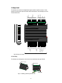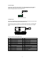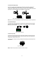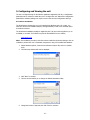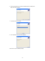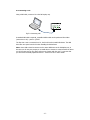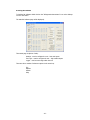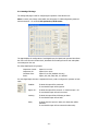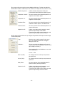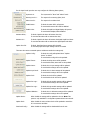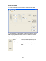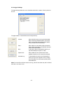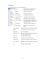
1
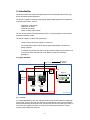
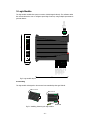
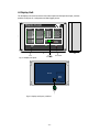
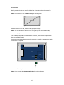
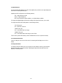
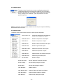
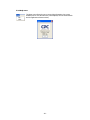
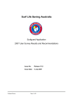
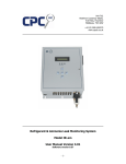
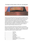
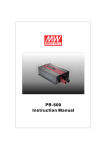
Unit 7/8,
Heathrow Causeway Estate,
Ariel Way, Hounslow
Middlesex, TW4 6JW
+44 (0) 208 6302270
Refrigeration Annuciator
Compressor Pak Monitoring System
User Manual Version 2.2
-1-
All rights reserved
The information contained in this manual has been carefully checked and is believed to be
accurate. However, CPC (UK) Ltd assumes no responsibility for any inaccuracies that may be
contained herein. In no event will CPC (UK) Ltd, be liable for any direct, indirect, special,
incidental, or consequential damages resulting from any defect or omission in this manual,
even if advised of the possibility of such damages. In the interest of continued product
development, CPC (UK) Ltd reserves the right to make improvements to this manual, and the
products described herein, at any time without notice or obligation.
Copyright
Copyright by CPC (UK) Ltd. No part of this manual may be reproduced or transmitted in any
Form without express written authorization from CPC (UK) Ltd.
Trademarks
All trademarks are acknowledged and are the property of their respective holders.
Contact Details
If you have any questions about this document, or the products it describes – please contact CPC
UK;
Tel : +44 (0) 208 6302270
Email : [email protected]
-2-
Contents
1. Introduction ............................................................................................................. 4
1.1 Typical schematic ................................................................................................ 4
2. Base Unit ................................................................................................................. 6
2.1 Mounting............................................................................................................ 6
2.2 Power supply ...................................................................................................... 7
2.3 Digital inputs ...................................................................................................... 7
2.4 Liquid level analogue input ................................................................................... 8
2.5 Communication port ............................................................................................ 8
2.6 Alarm relay output .............................................................................................. 8
2.7 LED Indicators .................................................................................................... 9
2.8 Reset button....................................................................................................... 9
3. Logic Module ...........................................................................................................10
3.1 Mounting...........................................................................................................10
3.2 Power supply .....................................................................................................11
3.3 240VAC Inputs ...................................................................................................11
3.4 Communication port ...........................................................................................11
3.5 LED Indicators ...................................................................................................11
4. Display Unit ............................................................................................................12
4.1 Mounting...........................................................................................................13
4.2 Power Supply & Communication Port ....................................................................13
4.3 LED Indicators ...................................................................................................14
4.4 Communications Port ..........................................................................................14
4.5 Lamp test button ...............................................................................................14
5. Configuring and Viewing the unit ...............................................................................15
5.1 Software Installation ..........................................................................................15
5.2 Connecting a unit ...............................................................................................17
5.3 Using the software .............................................................................................18
5.3.1 Settings Tab Page........................................................................................19
5.3.2 Fan Logic Tab Page .....................................................................................22
5.3.3 Logger Tab Page .........................................................................................25
5.3.4 File menu ...................................................................................................26
5.3.5 Options menu .............................................................................................27
5.3.6 Actions menu ..............................................................................................27
5.3.8 Help menu ..................................................................................................28
5.4 Liquid Level Alarm Strategy .................................................................................29
6. Revisions ................................................................................................................30
-3-
1. Introduction
This manual outlines the features and specifications for the Refrigeration Annunciator (RA),
and its associated software application.
The RA unit is capable of monitoring and logging multiple digital signals from a refrigeration
compressor pak systems, such as;
Compressor control alarms
Compressor oil alarms
Condenser fans faults
Various common system alarms
The unit can also monitor the refrigerant liquid level, via a remote liquid level sensor with a
proportional analogue output.
The RA unit comprises of three main components;
The base unit to which input signals are connected.
The 240VAC logic module to which 240VAC input signals maybe connected (not
always required).
The display unit indicates the status of all the monitored inputs and also allows users
to access unit setup and read logs via its USB port (using the RA software
application).
1.1 Typical schematic
Fig 1 Schematic
In a typical application the base unit and logic module will be housed within the existing Pak
control panel, power for the base unit will come from the existing control circuit transformer.
Where possible existing fault signals will be connected into the base unit and logic module, in
some cases fault signals may require re-wiring of the control panel making use of spare
contacts within existing fault relays etc.
-4-
The base unit and logic module must be mounted within the control panel, deterring users
from resetting alarms frequently (which is done via the base unit).
The display unit will be mounted inside the main Pak enclosure – in an easily accessible and
visible location. There will be separate connection cables between the base unit, logic module
and the display unit.
The liquid level sensor will be located near to the liquid receiver, which maybe inside the
main Pak enclosure, or at the Condenser.
There will also be a connection between the base unit and a remote monitoring unit, this
maybe the existing Pak controller or a secondary networked monitoring unit.
Note: For site and pack specific installation details, procedures and wiring schematics please
contact CPC UK.
-5-
2. Base Unit
The RA base unit monitors the digital alarm signals and the liquid level sensor. It also
provides an alarm relay output and sends status information to the RA display unit via a
communications link.
Power
Alarm
Relay
UK
22
Liquid Level (Digital)
SHT Pak Shutdown
LLV
BAC Pak In Backup
DHP Discharge High Press.
Compressor
Oil Alarm
Inputs
Condenser
Fan Alarm
Inputs
Suction Low Press.
SHP Suction High Press.
SLP
CO3
CO4
CO5
CO6
CO7
CO8
CO9
CO10
CF1
CF2
CF3
CF4
CF5
CF6
AN -
DCC
DCB
DCA
NC
COM
NO
Not Used
Reset
Not Used
Relay
24VAC
Status
24VAC
Supply
AN +
CC1
CC2
CC3
CC4
CC5
CC6
CC7
CC8
CC9
CO1
CC10
CO2
Fig 2.1 Installing, Removing RA base unit
Display Panel
Comms. Link
105
-6-
Liquid Level
Analog Input
Compressor
Control Alarm
Inputs
Compressor
Oil Alarm
Inputs
Refrigeration
Annuciator
Fig 2 RA base unit layout
120
2.1 Mounting
The RA base unit is designed to be mounted onto standard top-hat type DIN rail.
2.2 Power supply
Power must be connected to the unit via the power input connections; the unit requires a
24VAC supply voltage (1A maximum load). It is recommended that a 2A fuse is fitted
between the supply transformer and the RA base unit;
Fig 2.2 Power connections
2.3 Digital inputs
The unit has 32 digital inputs. All inputs function electrically in the same way, however inputs
maybe inverted when configuring the software within the unit.
Inputs sense the presence, and absence of a 24VAC voltage at the input. The 24VAC supply
voltage should be passed through the remote alarm contact, and connected to the digital
input;
Fig 2.3 Alarm input connections
The unit provides the following digital inputs;
ID
CC1
CC2
CC3
CC4
CC5
CC6
CC7
CC8
CC9
CC10
CO1
CO2
CO3
CO4
CO5
CO6
Description
Compressor
Compressor
Compressor
Compressor
Compressor
Compressor
Compressor
Compressor
Compressor
Compressor
Compressor
Compressor
Compressor
Compressor
Compressor
Compressor
1 Control Alarm
2 Control Alarm
3 Control Alarm
4 Control Alarm
5 Control Alarm
6 Control Alarm
7 Control Alarm
8 Control Alarm
9 Control Alarm
10 Control Alarm
1 Oil Alarm
2 Oil Alarm
3 Oil Alarm
4 Oil Alarm
5 Oil Alarm
6 Oil Alarm
ID
CO7
CO8
CO9
CO10
CF1
CF2
CF3
CF4
CF5
CF6
SLP
SHP
DHP
BAC
LLV
SHT
-7-
Description
Compressor 7 Oil Alarm
Compressor 8 Oil Alarm
Compressor 9 Oil Alarm
Compressor 10 Oil Alarm
Condenser Fan 1 Alarm
Condenser Fan 2 Alarm
Condenser Fan 3 Alarm
Condenser Fan 4 Alarm
Condenser Fan 5 Alarm
Condenser Fan 6 Alarm
Suction Low Pressure Alarm
Suction High Pressure Alarm
Discharge High Pressure Alarm
Pak Running In Backup
Low Liquid Level Alarm
Pak Shutdown
2.4 Liquid level analogue input
The unit has a single 0-5VDC analogue input, which can be connected to a Liquid Level
sensor. The exact parameters, sensing range etc. of the input can be changed when
configuring the software within the unit. The input can also be used to measure a liquid level
sensor with a 4-20mA output signal, with the addition of a 250R resistor;
Fig 2.4 Analogue input connections
Note: Refer to the sensor documentation for sensor end connections and PSU requirements.
2.5 Communication port
The RA base units communication port is connected to the communication port on the RA
display unit. As well as sending status information to the RA display, power for the display
also comes via this connection.
Fig 2.5 Comms connection
2.6 Alarm relay output
The alarm relay output will activate when certain alarm conditions are detected by the RA
base unit. The exact conditions required to activate the alarm relay can be changed when
configuring the software within the unit.
The alarm relay is a change-over relay, providing both Normally Open and Normally Closed
relay contacts;
Fig 2.6 Alarm Relay
Note: The alarm relay contacts are rated at 1A 240VAC / 30VDC.
-8-
2.7 LED Indicators
The RA base unit includes three LED indicators, these indicate the following conditions;
Green LED = Power, Illuminated if unit is powered up correctly.
Yellow LED = Status, Will flash when a new alarm is detected.
Red LED = Relay, Illuminated if the alarm relay is activated.
2.8 Reset button
The reset button enables users to reset latched alarms. When configuring the software within
the unit, it is possible to set a particular alarm input to latch permanently into an alarm state
(regardless of the physical state of the input), until the reset button is pressed.
-9-
3. Logic Module
The logic module enables the system to monitor 240VAC signals directly. The software within
the unit also allows the user to configure special logic functions, using multiple input states to
generate alarms.
Display Panel
Comms. Link
DCB
CF1 Condenser Fan 1
FC1 Fan control 1
DCA
DCC
Refrigeration
Annuciator
Supply
Status
105
240VAC
LOGIC
MODULE
UK
22
N Neutral
CF2 Condenser Fan 2
FC2 Fan Control 2
CF3 Condenser Fan 3
CF4 Condenser Fan 4
FC3 Fan Control 3
CF5 Condenser Fan 5
CF6 Condenser Fan 6
120
Fig 3 Logic module layout
3.1 Mounting
The logic module is designed to be mounted onto standard top-hat type DIN rail.
Fig 3.1 Installing, Removing the logic module
- 10 -
3.2 Power supply
Power is supplied to the logic module via the communication port.
3.3 240VAC Inputs
The unit has 9 x 240VAC inputs which are used to monitor the presence of a 240VAC signal
at the input.
Fig 3.2 240VAC input connections
The following inputs are available;
ID
FC1
CF1
CF2
FC2
CF3
CF4
FC3
CF5
CF6
Description
Fan Control 1
Condenser Fan
Condenser Fan
Fan Control 2
Condenser Fan
Condenser Fan
Fan Control 3
Condenser Fan
Condenser Fan
1
2
3
4
5
6
3.4 Communication port
The logic modules communication port is connected to the communication port on the RA
display unit. As well as sending status information to the RA display, power for logic module
comes via this connection.
Fig 3.3 Comms connection
3.5 LED Indicators
The logic module includes two LED indicators; these indicate the following conditions;
Green LED = Power, Illuminated if unit is powered up correctly.
Yellow LED = Status, Will flash when a new alarm is detected.
- 11 -
4. Display Unit
The RA Display unit shows the status of the alarm inputs and the liquid level input, and also
provides a USB port for configuration and data-logging access.
120
Fig 4.1 Display unit layout
Base Unit
Comms. Link
- 12 -
DCC
DCB
DCA
Fig 4.2 Display unit layout, inside lid
4.1 Mounting
Before mounting the unit, you must first drill at least 2 x mounting holes in the base of the
RA Display unit.
Note : Remove the lid of the unit before drilling the mounting holes.
Fig 4.3 Mounting holes
Attached the base to the wall, enclosure using appropriate fixings.
Note : You may also need to drill a hole for a cable gland (for the communication cable).
4.2 Power Supply & Communication Port
The RA display unit provides 2 communications connectors, either connector maybe used as
they are electrically identical.
Power and communication data is sent via this connection; therefore a separate power supply
connection is not required;
Main PCB
Daughter
Board
Base Unit
Comms. Link
DCC
DCB
DCA
Base Unit
Comms. Link
Fig 4.4 Display unit comms connection
Note : Refer to section 2.5 Communication Port for further information.
- 13 -
4.3 LED Indicators
The unit includes LED indicators for each of the digital inputs, and also a two digit display and
status LED’s for the liquid level input.
Digital input LED’s will operate in the following manner;
Off = Input channel not used
Green = Input channel OK
Red = Input channel in alarm condition, or in latched alarm condition
The Liquid level digital display will show the reading of the liquid level sensor, 0% to 99%.
The Liquid level status LED’s will operate in the following manner;
“OK” LED (green)
On = Sensor OK, Level OK
“ALERT” LED (red)
On = Level within Alert level range
“ALARM” LED (red)
On = Level within Alarm level Range or Sensor Fault
There is also a power LED indicator, which will illuminate if the unit is powered correctly.
4.4 Communications Port
There is a USB port on the front of the unit for connecting the RA display unit to a PC or
laptop.
4.5 Lamp test button
The lamp test button enables the user to perform an LED indicator self test, press and hold
the lamp test button to start the self test. Releasing the lamp test button will return the
display to normal operation.
- 14 -
5. Configuring and Viewing the unit
The unit is configured using the RA software application supplied by CPC UK, a configuration
password must be entered to enable the user to configure the unit. Without the configuration
password the software package can only be used to view the units configuration and logs.
5.1 Software Installation
The RA Software is designed to run on PC installed with Windows 2000, XP or Vista. You
must have at least one available USB port, and approximately 3.5mb of free hard disk space
to install the software.
The RA Software installation package is supplied by CPC (UK) and can be supplied to you on
a CDROM, or via Email. The software may also be downloaded from our website,
www.cpcuk.co.uk
Note : The installation procedure, and other sections within this document relating to the use
of Windows, assume the user is reasonably competent in using a PC installed with Windows.
1. Within Windows explorer, locate the RA Software setup.exe file, and run it (double
click).
2. The main setup window will now be displayed;
3. Click “Next” to continue.
4. The next screen enables you to change the default destination folder;
5. Change the location if required, then click “Next” to continue.
- 15 -
6. The next screen allows you to confirm the installation before the install process
begins, click “Next to continue”;
7. The software will now be installed.
8. Once completed the final screen will be displayed;
9. Click “Close” to exit the installation package.
- 16 -
5.2 Connecting a unit
Using a USB cable, connect a PC to the RA Display unit,
Fig 5.0 Connecting a PC
A standard USB cable is required, a suitable USB be cable can be purchased from Misco
(www.misco.co.uk) – part no. Q77025
The first time a unit is connected to a PC, the PC will need to install USB drivers. The USB
driver files are copied onto the PC when installing the RA Software.
Note : Some USB to Serial converters use the same USB drivers as the RA display unit, in
this case your PC may not prompt you to install drivers. However in some instances the driver
you do have may not be up to date, and may not function with the unit. To overcome this
you will need to manually update the drivers – contact CPC UK for more details.
- 17 -
5.3 Using the software
To load the RA Software double click on the “Refrigeration Annunciator” icon on the desktop
or in the start menu.
The main RA Software page will be displayed;
There main page is split into 3 tabs;
Settings - used to configure the unit – base unit inputs
Fan Logic – used to configure the unit – logic module inputs
Logger - used to access logs within the unit
There are also a number of submenu options in the menu bar;
File
Options
Actions
Help
- 18 -
5.3.1 Settings Tab Page
The settings tab page is used for configuring the operation of the RA base unit.
Note: You many only change values within the setup page if a valid configuration password
has been entered – see section 5.3.5 Options drop down menu.
The page displays the configuration of each digital input, the liquid level input and also allows
the user to set the units real-time clock, download current settings from the unit and update
new settings into the unit.
For clarity digital inputs are grouped;
Compressor Control –
Compressor Oil Condenser Fans Faults -
Inputs CC1 to CC10
Inputs CO1 to CO10
Inputs CF1 to CF6 (RA Base unit only)
Inputs, SLP, SHP, DHP, BAC, LLV and SHT
For each digital input there are 4 separate tick boxes, used to configure the operation of each
input;
Enabled –
If ticked the input will be monitored.
If not ticked the input will be ignored.
High is OK -
If ticked the input will be inverted – ie 24VAC at input = OK
If not ticked the input will not be inverted.
Latching -
If ticked the input will latch following an alarm.
If not ticked the input will not latch.
Relay -
If ticked when the input is in alarm, the alarm relay will be
activated.
If not ticked the input will not activate the alarm relay.
- 19 -
For input group the user may also setup a validation delay timer. The input must be in the
desired alarm condition continuously for the duration of the delay timer for an alarm to occur;
Enable delay timers –
If ticked the alarm delay timers will be used
If not ticked the alarm delay timers will be ignored.
Compressor Controls -
The time in seconds of the alarm delay timer for all
compressor control alarm inputs.
Compressor Oil -
The time in seconds of the alarm delay timer for all
compressor oil alarm inputs.
Condenser Fans -
The time in seconds of the alarm delay timer for all
condenser fan alarm inputs on the RA base unit.
Common Faults -
The time in seconds of the alarm delay timer for all
common fault inputs.
Update from file -
If ticked, when loading saved settings the saved
liquid level input settings will be loaded.
If not ticked, when loading saved settings the saved
liquid level input settings will not be loaded.
For the Liquid Level input the user may configure the operation of the input to suite the type
of sensor being used;
Type -
Allows the user to specify a name for the sensor
type – this should be entered when saving the
settings for future use.
Calibration -
The user may adjust the calibration of the Liquid
Level input, the value will specify the actual % of the
input reading to be used, ie
If input reading is 50% and calibration is set to 90%
then reading will be,
50 x 0.9 = 45%
99% at (Volts) -
The voltage to be seen at the input to represent
99% liquid level.
0% at (Volts) -
The voltage to be seen at the input to represent 0%
liquid level
Delay Timer -
The time in minutes of the alarm delay timer for
liquid level alarms (Warning and Alarm)
Update from file -
If ticked, when loading saved settings the saved
liquid level input settings will be loaded.
If not ticked, when loading saved settings the saved
liquid level input settings will not be loaded.
- 20 -
For the Liquid Level input the user may configure the following alarm options;
Hysteresis % -
The Hysteresis for “Alert” and “Alarm” levels.
Warning Level % -
The setpoint for a warning (Alert) level.
Alarm Level % -
The setpoint for an Alarm level.
Enable Status -
If ticked the status LED’s will operate.
If not ticked the status LED’s will be disabled.
Enable Value -
If ticked the liquid level digital display will operate.
If not ticked the display will be disabled.
Activates Relay -
If ticked a liquid level alarm will activate the relay.
If not ticked the alarm will not activate the relay.
Activates LLV -
If ticked a liquid level alarm will activate the digital Liquid level alarm
If not ticked the alarm will not activate the digital liquid level alarm.
Update from file -
If ticked, liquid level input settings will be loaded.
If not ticked, liquid level input settings will not be loaded.
There are also various command options and buttons within the settings tab;
Update Config -
If ticked the config will updated when “Update
Device” is clicked.
If not ticked the config will not be updated.
Update Timers -
If ticked the delay timers will be updated.
If not ticked the delay timers will not be updated.
Update Sensor -
If ticked the LLV input settings will be updated.
If not ticked the settings will not be updated.
Update Liquid Level -
If ticked the LLV alarm settings will be updated.
If not ticked the settings will not be updated.
Update Clock -
If ticked the clock will be updated.
If not ticked the clock will not be updated.
Update Fan Logic -
If ticked the logic module settings will be updated.
If not ticked the settings will not be updated.
Update Fan Logic -
If ticked the logic module settings will be updated.
If not ticked the settings will not be updated.
Update Calibration -
If ticked the LLV calibration settings will be updated.
If not ticked the settings will not be updated.
Update Device -
When clicked the settings will be updated to the unit. Note: This
option is only available if a configuration password has been entered.
Update Clock -
When clicked the units real-time clock will be updated to match the
PC’s current time and date.
Download Config –
When clicked the settings will be downloaded from the unit.
- 21 -
5.3.2 Fan Logic Tab Page
The fan logic tab page allows the user to configure the operation of the logic module;
The screen allows the user to setup a maximum of 8 special gate functions. Gate functions
enable up to three separate inputs on the logic module to be passed through logic gates,
before setting a single condenser fan alarm.
The user must select if the default logic module configuration is to be used, or if custom
configuration is to be used;
Default -
If selected the default configuration will be used.
Program -
If selected the custom configuration will be used.
Update from file -
If ticked, logic module settings will be loaded.
If not ticked, logic module settings will not be
loaded.
- 22 -
If user has selected a custom configuration, they must first select the gate function to
configure,
Gate 1…8 -
Select the gate you wish to configure.
The user must then select the inputs which will be used within the gate
Only inputs on the Logic module will be used. A maximum of three inputs
maybe selected – A, B, C. It is also possible to select the result of another
gate as an input for a gate.
It is possible to select a number of states which will activate an alarm, the
example shown requires all three inputs to be activated for an alarm to
occur.
Finally the user must select which display alarm output will be activated
following an alarm.
- 23 -
The default operation of the logic module is;
Gate 1
Input
A – FC1
B – CF1
C - None
Alarm Logic
0
0
-
Gate 2
Input
A – FC1
B – CF2
C - None
Alarm Logic
0
0
-
Gate 3
Input
A – FC2
B – CF3
C - None
Alarm Logic
0
0
-
Gate 4
Input
A – FC2
B – CF4
C - None
Alarm Logic
0
0
-
Gate 5
Input
A – FC3
B – CF5
C - None
Alarm Logic
0
0
-
Gate 6
Input
A – FC3
B – CF6
C - None
Alarm Logic
0
0
-
Condenser Fan 1
Condenser Fan 2
Condenser Fan 3
Condenser Fan 4
Condenser Fan 5
Condenser Fan 6
- 24 -
5.3.3 Logger Tab Page
The logger tab page allows the user to download and view the contents of the log stored on
the unit.
The page includes 4 command buttons and a single tick box;
Unerase -
When ticked all events in the log will downloaded.
When not ticked (the default option), only events
which occurred after the last erase (erase marker
entry) took place will be downloaded.
Erase -
When clicked an erase marker will be entered into
the log. Only events which occurred after this erase
marker will be downloaded.
It may take a while to download the entire log, to
stop downloading the log click on “Stop”.
Stop -
Update Clock -
When clicked the units real-time clock will be
updated to match you PC’s current time and date
Download Log -
To download the log click on the “Download log”
button, the log will now appear in the log viewing
area of the page. The most recent log entry will be
downloaded first.
Note: The unit will record 16000 entries in the log, when full the oldest entry will be deleted
each time a new event occurs.
- 25 -
5.3.4 File menu
The file menu allows the user to save and load settings,
New -
Clears all the current settings within the
settings and fan logic tab pages.
Open -
Loads saved units settings.
Save As -
Saves the current settings.
Open Settings -
Loads digital input settings only.
Open Liquid Level -
Loads liquid level alarm settings only.
Open Timers -
Loads input delay timer settings only.
Save As Template -
Saves all the settings as a template file.
These will be the settings loaded each time
you start the software.
Open Sensor -
Loads liquid level sensor settings only.
Save Sensor As -
Saves the current liquid level sensor
settings.
Sensor to Default -
Resets the liquid level sensor settings to the default.
Open Log -
Loads a saved log so that it can be viewed.
Save Log As -
Saves the log displayed.
Export Log as Text -
Exports the log displayed within the Logging tab, the
log will be exported as a text file.
Open Logic -
Loads logic module settings only.
Save Logic As -
Saves the current logic module settings.
Open Function -
Loads the logic module gate function settings only.
Save Function As -
Saves the current logic module gate function settings
only.
Exit -
Exits the RA software application.
- 26 -
5.3.5 Options menu
The options menu allows the user to enter a configuration password. A
configuration password must be entered to enable the user to be able to
download new setting to a unit, update the units real-time clock and erase
the log. Clicking on the “password..” option will present the user with
password input box,
Note: A configuration password maybe obtained from CPC UK upon request and following
authorization from the end user.
5.3.6 Actions menu
The actions menu provides various short cuts to speed up unit configuration.
Copy Control to Oil -
Copies input settings from the compressor
control to the compressor oil inputs.
Enable All Controls -
Enables all compressor control inputs.
Enable All Oils -
Enables all compressor oil inputs.
Enable All Fans -
Enables all base unit condenser fan inputs
Enable All Faults -
Enables all general fault inputs.
Disable All Controls -
Disables all compressor control inputs.
Disable All Oils -
Disables all compressor oil inputs.
Disable All Fans -
Disables all base unit condenser fan inputs
Disable All Faults -
Disables all general fault inputs.
Set All Enables -
Enables all inputs
Set All High is OK’s -
Sets the “High is OK” setting for all inputs
Set All Latchings -
Sets the latching setting for all inputs
Set All Relays -
Sets the relay setting for all inputs
Clear All Enables -
Disables all inputs
Clear All High is OK’s - Clears the “High is OK” setting for all inputs
Clear All Latchings -
Clears the latching setting for all inputs
Clear All Relays -
Clears the relay setting for all inputs
- 27 -
5.3.8 Help menu
The about menu allows the user to access help information (not current
available) and to view the about box, which displays CPC UK contact details
and the application software revision;
- 28 -
5.4 Liquid Level Alarm Strategy
The Liquid Level Alert will be activated if;
The Liquid Level Alert is not already active
And if the Liquid Level falls below the “Warning Level %”
The Liquid Level Alert will be de-activated if;
The Liquid Level Alert is already active
And if the Liquid Level rises above the “Warning Level %” + “Hysteresis %”
The Liquid Level Alarm will be activated if;
The Liquid Level Alarm is not already active
And if the Liquid Level falls below the “Alarm Level %”
The Liquid Level Alarm will be de-activated if;
The Liquid Level Alarm is already active
And if the Liquid Level rises above the “Alarm Level %” + “Hysteresis %”
- 29 -
6. Revisions
Rev
1.0
Date
12/08/2008
Software Rev
1.8
Changes
First revision of manual
2.0
28/08/2008
2.2
Added hardware details for logic module
Updated software installation
Revised Settings tab page
Added Fan Log tab page
Revised Logger tab page
Revised all drop down menus
2.1
09/09/2008
2.3
Minor amendmants
2.2
07/10/2008
2.9
Added liquid level alarm delays.
- 30 -