1
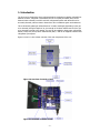
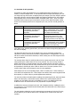
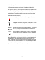
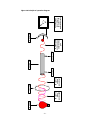
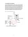
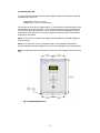
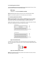
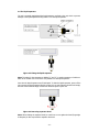
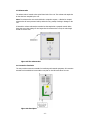
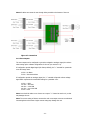
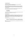
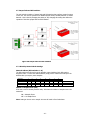
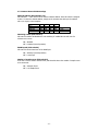
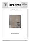
Unit 7/8,
Heathrow Causeway Estate,
Ariel Way, Hounslow
Middlesex, TW4 6JW
+44 (0) 208 6302270
www.cpcuk.co.uk
Refrigerant & Ammonia Leak Monitoring System
Model IR-em
User Manual Version 3.01
Software version 0.57
-1-
All rights reserved
The information contained in this manual has been carefully checked and is believed to be
accurate. However, CPC (UK) assumes no responsibility for any inaccuracies that may be
contained herein. In no event will CPC (UK), be liable for any direct, indirect, special,
incidental, or consequential damages resulting from any defect or omission in this manual,
even if advised of the possibility of such damages. In the interest of continued product
development, CPC (UK) reserves the right to make improvements to this manual, and the
products described herein, at any time without notice or obligation.
Copyright
Copyright by CPC (UK). No part of this manual may be reproduced or transmitted in any
Form without express written authorization from CPC (UK).
Trademarks
All trademarks are acknowledged and are the property of their respective holders.
-2-
Contents
1. Introduction ............................................................................................................. 5
1.1 Overview of unit operation ................................................................................... 6
1.2 Principle of operation........................................................................................... 7
2. Installing the unit hardware ....................................................................................... 9
2.1 Mounting the unit.............................................................................................. 10
2.2 Connecting power to the unit ............................................................................. 11
2.4 The liquid separator .......................................................................................... 12
2.5 Exhaust tube .................................................................................................... 13
2.6 Connection Terminals ........................................................................................ 13
2.6.1 Zone Outputs ............................................................................................. 14
2.6.2 RS485 Interface ......................................................................................... 15
2.6.3 Alarm Relays.............................................................................................. 15
2.7 Jumper links and DIP switches............................................................................ 16
2.7.1 Woodley Network Mode Settings .................................................................. 16
2.7.2 Camero Network Mode Settings ................................................................... 17
3. User Interface ........................................................................................................ 18
3.1 Basic user interface operation............................................................................. 18
3.1.2 Entering alphanumeric variables (names and passwords etc.) .......................... 18
3.1.3 Inactivity Timeout....................................................................................... 18
3.2 System screen layout......................................................................................... 19
3.3 Warm up screen ............................................................................................... 20
3.4 Status overview ................................................................................................ 20
3.5 System setup menu........................................................................................... 21
3.5.1 Change password - enter old password first................................................... 21
3.5.2 Change admin password ............................................................................. 21
3.5.3 Change user password ................................................................................ 21
3.5.4 Change zone output type ............................................................................ 21
3.5.5 Change date format .................................................................................... 22
3.5.6 Change date .............................................................................................. 22
3.5.7 Change time .............................................................................................. 22
3.5.8 Clear logs .................................................................................................. 22
3.5.9 Change alarm relay / LED setup ................................................................... 22
3.5.10 Change low reading threshold .................................................................... 23
3.5.11 Run self-test ............................................................................................ 23
3.5.12 More changes........................................................................................... 23
3.6 Manual override menu ....................................................................................... 24
3.7 Zone historical data menu .................................................................................. 25
3.7.1 Zone data-log ............................................................................................ 25
3.7.2 Zone alarm-log........................................................................................... 25
3.8 Zone setup menu .............................................................................................. 26
3.8.1 Change zone name ..................................................................................... 26
3.8.2 Change refrigerant type .............................................................................. 26
3.8.3 Change leak threshold................................................................................. 26
3.8.4 Change spill threshold ................................................................................. 27
3.8.5 Change sample period................................................................................. 27
3.8.6 Change leak alarm delay ............................................................................. 27
3.8.7 Change zone alarm thresholds ..................................................................... 27
3.8.8 Change zone alarm delay ............................................................................ 28
3.8.9 Change special handling modes.................................................................... 28
3.8.10 More changes........................................................................................... 28
4. Alarms................................................................................................................... 29
4.1 Zone alarm....................................................................................................... 29
4.2 Leak Alarm ....................................................................................................... 30
4.3 Spill Alarm........................................................................................................ 30
4.4 Flow Fault ........................................................................................................ 31
4.5 Alarm Buzzer ................................................................................................ 31
-3-
5. Unit specification .................................................................................................... 32
6. Technical Drawings ................................................................................................. 33
-4-
1. Introduction
The IR-em unit is designed to detect refrigerant leaks by analysing air samples collected from
different locations, refrigerant concentrations as low as 15 parts-per-million (PPM) can be
detected. Most commonly used HFC and HCFC refrigerants together with Ammonia can be
accurately detected, without nuisance alarms from other contaminant gases and substances.
This is achieved by passing an infrared beam of a certain wavelength (depending on the gas
to be detected) through a sample of air; the strength of the beam will become less if the gas
to be detected is present in the sample. The unit can be supplied to detect many refrigerants,
R404a, R134a, R22, R410a, R407c and Ammonia (NH3) – and can be supplied to detect other
refrigerants upon request.
Figures 1.0 and 1.1 show a basic overview of the main components of the unit.
Figure 1.0 Overview of exterior of unit
Figure 1.1 Overview of interior of unit
-5-
1.1 Overview of unit operation
Air samples are taken sequentially from up to 16 different locations (8 locations on some
models), via filtered sample tubes. To accommodate different sample tube lengths, the user
can setup how long each location is sampled, during the sample cycle. Each sample is passed
through the IR bench, and the gas level within the sample is determined. For each location
being sampled, there are three different alarm thresholds called “Leak”, “Zone” and “Spill”
thresholds. When measured gas concentrations rise above these alarm thresholds, further
actions can be initiated (which can be configured by the user) and the unit will generate an
alarm.
Alarm
Leak Alarm
Zone Alarm
Spill Alarm
Occurrence
Will occur when a measured gas
concentration rises above the
corresponding Leak alarm
threshold.
Will occur when a measured gas
concentration rises above the
corresponding Zone alarm
threshold.
Will occur when a measured gas
concentration rises above the
corresponding Spill alarm
threshold.
Normal Action Initiated
Leak LED illuminated, common alarm
relay 1 changes state, entry recording
refrigerant concentration, time and
zone name in the alarm-log.
Status LED will turn red, the output for
that channel is raised to 5V, entry
recording refrigerant concentration,
time and zone name in the alarm-log.
Spill LED illuminated, common alarm
relay 2 changes state, entry recording
refrigerant concentration, time and
zone name in the alarm-log.
Every alarm event, including system faults, will result in an alarm message being displayed on
the units LCD display.
The filtered air tubes that carry the air sample to the unit are constantly monitored for
reductions in air flow, which can be caused by a squashed tube or a clogged filter. The unit
will raise an alarm if low airflow is detected, in effect warning the user that refrigerant leaks
may go undetected.
The common alarm relays R1 and R2 provide volt free contacts rated at 230 VAC 2A. These
relays provide open contacts when the unit is not powered. The user can setup normal or
failsafe relay actions. In normal operation the relay contacts will close only when a fault or
alarm occurs. In fail-safe mode the relay contacts will close as soon as the unit is powered up
and operational, and will open when a fault or alarm occurs. The exact operation of the
common alarm relays can be changed to suite the users application.
Each sample zone has a corresponding output, which is normally set to +5VDC following a
zone alarm for that particular zone. These outputs can interface with external equipment and
alarm panels, or to other relays to provide supplementary switching.
The unit also includes an RS485 interface enabling the measured gas levels, status and alarm
data to be collected by a central alarm system. Details of the communication protocols
available over the RS485 connection are available on request. The RS485 interface also
enables the unit to be connected to the CPC (UK) Einstein 2 system manager.
In addition the unit may connected to the CPC (UK) Viewpoint interface, enabling the unit to
be connected to a TCP-IP based network allowing status and alarm data to be viewed using a
standard web browser.
The unit maintains a data-log record of measured gas concentrations for the last 72 hours,
and an alarm-log of the last 50 alarm events. This data can be viewed via the units LCD
interface.
-6-
1.2 Principle of operation
The IR-em gas monitoring system uses the principle of Non-Dispersive Infrared (NDIR)
absorption to measure refrigerant or ammonia gas concentrations in the atmosphere.
Most gases absorb Infrared (IR) light to some extent, with different gases absorbing a certain
wavelength’s of IR light. Higher gas concentrations in a certain volume of air, mean that
more molecules of that gas will be present. The greater the number of gas molecules present
in the path of an IR light beam, the more IR radiation of a certain wavelength will be
absorbed. Therefore, measuring how much IR light of a certain wavelength passes through a
sample of air; we can determine how much gas of certain type is present in that sample.
The essential components of the unit are:
IR Source
A source of IR radiation. The IR source will actually produce IR radiation at a
range of different wavelengths, covering the entire Infrared band which
extends to visible light.
IR Filter
An optical filter used to select a specific band of IR light, centred on a certain
wavelength – the wavelength for the gas to be measured. The unit uses one
filter for the gas to be measured, and another filter for reference.
Sample Cell
The sample to be measured is transported into a sample cell. The windows at
each end of the sample cell allow the IR radiation from the IR Source, to
pass through the sample.
IR Detector
A detector sensitive to IR light wavelengths. The detector provides a voltage
output; the level of the voltage depends on the amount of IR light detected.
The actual gas concentration is determined by measuring the difference in the amount of IR
light received by the IR detector, after passing the IR light beam through the gas IR optical
filter and separately through another reference optical filter (an optical filter allows through a
certain IR wavelength which will not be absorbed by any gas likely to be present in the
sample). The differential measurement technique provides long term stability which prevents
any accuracy drop due to long term degradation of the IR source, as the IR detector will be
see the same drop in IR light level after it has been passed through both IR optical filters.
Figure 1.0 illustrates the basic principle of an IR gas detection system.
-7-
IR Source
IR Light of
many
wavelength’s
IR Light at
certain
wavelength
IR Filter
Sample in
Sample out
Sample cell
IR Light after
some has been
absorbed by
gas
IR Detector
Voltage varies
according to
amount of IR
radiation detected
Figure 1.0 Principle of operation diagram.
-8-
2. Installing the unit hardware
The unit is normally mounted in a plant room, corridor or office – typically in a location that is
not accessible to the general public. The unit must be connected to a 240VAC mains supply
from an un-switched fused spur, which is normally provided by qualified electricians prior to
installation. Colour coded sample tubes are taken from the unit to the sample point locations:
such as compressors, condensers, pressure relief valves, cold rooms, chilled display cases, air
conditioning units, valve assembly’s etc. Each sample point must be terminated with an air
filter, preventing dust and dirt travelling back to the unit. A secondary in line filter must be
fitted near the unit just before connection to the units manifold, protecting the unit from dirt
and dust in the event of a damaged or missing end of line air filter. Connections are then
made to optional secondary equipment (such as alarm beacons, auto diallers etc.) via its
outputs, and also to a central alarm system via the units RS485 interface (if required).
Figure 2.0 Illustrates a typical application schematic.
Figure 2.0 Schematic of typical application
-9-
2.1 Mounting the unit
The unit should be mounted in a location where ambient conditions are within the specified
operating range for the unit,
Temperature range: 5°C to 40°C
Humidity (RH) : < 95%, non-condensing
The unit must be secured in an upright position, to a wall using the mounting brackets at the
top and bottom of the unit (see figure 2.1 for mounting dimensions). Allow at least 150mm
on the left and right hand sides of the unit for access to terminals and ventilation. Allow at
least 200mm underneath the unit for access to manifold connections and so that the liquid
separator can be emptied.
Note: The unit must be mounted in an upright (vertical) position for the liquid separator to
function correctly.
Note: Do not mount the unit on a refrigeration pack or other apparatus that produces
excessive vibrations. Excessive vibrations may cause serious damage to the units IR detector.
Note: It is advised that the unit should be mounted so the LCD is slightly above average eye
level.
Fig 2.1 Mounting dimensions
- 10 -
2.2 Connecting power to the unit
The unit is supplied with three wires protruding from the right-hand side of the unit. These
wires should be connected to the 240VAC power supply:
Brown – Live
Blue – Neutral
Yellow/Green – Earth (the unit MUST be earthed!)
Note: Qualified personnel should only connect the unit to the 240VAC power supply.
Note: The unit should be supplied from a fused switch spur (fuse rating 5A).
2.3 Connecting sample tubes and filters
Note: This manual explains the final connection of sample tubing to the unit. A separate
manual detailing installation of tubing throughout the site (including suggested sampling
points, types of filters and remote manifolds available) is available from CPC (UK).
Sample tubes should be connected to the manifold intake nozzles at the bottom of the unit.
Each nozzle is identified with a number, the sample zone number.
Figure 2.1 Manifold nozzles
To connect a tube, first ensure the end of the tube has been cut off at right angles to the
tube, then simply push the tube into the nozzle. The tube should travel approximately 10mm
into the nozzle.
Figure 2.2 Connecting tube to nozzle
Note: On early models the tube must be pushed over the outside of the nozzle, a barb on
the nozzle holds the tube in place.
- 11 -
2.4 The liquid separator
The unit is normally supplied with the liquid separator not fitted to the unit; this is to prevent
damage to the liquid separator during transit. To fit the liquid separator:
Figure 2.3 Fitting the liquid separator
Note: The tubes for the separator are labeled “1” and “2”, it maybe necessary to feed these
tubes to the outside of the unit before it is possible to fit the liquid separator.
Over time the liquid separator may fill with liquid. To drain the liquid separator, power off the
unit, unscrew the liquid separator bowl by turning it in an anti-clockwise direction and empty
the bowl. When finished simply re-attach the bowl and power up the unit.
Figure 2.4 Removing separator bowl
Note: When refitting the separator bowl, be careful not to over tighten the bowl (finger tight
is adequate) as this may break the separator bowl seal.
- 12 -
2.5 Exhaust tube
The exhaust tube is located at the top left-hand side of the unit. The exhaust tube expels the
air that has been sampled by the unit.
Note: The exhaust tube must not be blocked or crimped in anyway - a blocked or crimped
exhaust tube will cause pressure build up within the unit, possibly resulting in damage to the
unit.
If desired the exhaust tube maybe extended so that sampled air is pumped outside. When
doing this ensure that tubing one size larger than the exhaust tube is used, the tube length
should not exceed 10m.
Figure 2.5 The exhaust tube
2.6 Connection Terminals
The unit provides connection terminals for interfacing with external equipment. All connection
terminals are located behind a removable cover plate on the left-hand side of the unit.
Figure 2.6 Gland plate
- 13 -
Note: All cables must enter the unit through holes provided on the bottom of the unit.
Figure 2.7 Connections
2.6.1 Zone Outputs
The zone outputs can be configured to give either a digital or analogue signal, this is done
when setting up the software configuration of the unit (see section 3.5.4).
If configured to provide digital signal (the factory default), the “+” terminal for a particular
zone will change state:
0 VDC = No Alarm
5 VDC = Zone Active Alarm
If configured to provide an analogue signal, the “+” terminal will provide a linear voltage
signal which represents the actual PPM reading for a particular zone:
0 VDC = 0 PPM
2.4 VDC = 600 PPM
4.8 VDC = 1200 PPM
4.9 VDC = over 1200 PPM
5 VDC = Fault
Note: Care should be taken not to short a zone output “+” channel to earth or 0V, as this
may damage the unit.
Note: The current rating of devices connected to each zone output must not exceed 40mA.
Connecting devices that have a higher current rating may damage the unit.
- 14 -
2.6.2 RS485 Interface
The unit provides an RS485 interface, enabling the unit to transmit data to building
management systems and other central alarm systems.
There are two RS485 communication protocols supported by the IR-em unit, Camero and
Woodley. The Camero protocol is used to communicate to the Viewpoint and Einstein 1 & 2
system managers. Woodley is a third party “open” communication protocol used within the
refrigeration industry.
Connection between the unit and the remote system should be made using Belden cable
8761 (or equivalent), the cable should be connected as follows:
Black = RS485 +
White = RS485 –
Screen = Screen
The characteristics of the RS485 interface (such as address, protocol and baud rate) must be
configured using the units DIP-switches (see section 2.7).
2.6.3 Alarm Relays
The alarm relays may each be configured to provide a signal to another device in the event of
a spill alarm, leak alarm or system fault. It is also possible to configure each relay to operate
as Normally Open (NO) or Normally Closed (NC) – providing failsafe operation. The exact
operation of alarm relays is selected when setting up the software configuration of the unit
(see section 3.5.9).
The factory default operation of the alarm relays:
Alarm relay 1 = Relay contacts will close in the event of a Spill Alarm (NO operation)
Alarm relay 2 = Relay contacts will close in the event of a Leak Alarm (NO operation)
Note: The alarm relay contacts are rated at 240VAC 3A. Connecting devices that exceed this
rating may damage the unit.
- 15 -
2.7 Jumper links and DIP switches
The unit includes a number of jumper links and DIP-switches that configure certain functions
on the unit. The unit can operate in two RS485 network modes, Woodley Network or Camero
Network – this is done by changing the setting of JP5, changing this setting also defines the
operation of the other jumper links and DIP-switches.
Figure 2.8 Jumper links and DIP-switches
2.7.1 Woodley Network Mode Settings
Network Address (DIP-switches 1 – 8)
The DIP-switches are all used to set the Woodley network address. Each DIP-switch is
assigned a value. To select the desired address, simply set the switches that add up to the
address value you require, some examples:
Switch No.
Value
Address 21
Address 67
Address 200
1
1
ON
ON
OFF
2
2
OFF
ON
OFF
3
4
ON
OFF
OFF
4
8
OFF
OFF
ON
5
16
ON
OFF
OFF
6
32
OFF
OFF
OFF
7
64
OFF
ON
ON
8
128
OFF
OFF
ON
16+4+1=21
64+2+1=67
128+64+8=200
Number of sample zones (JP6)
If the unit is set for Woodley network mode, JP6 selects the number of sample zones to be
monitored:
ON = 8 Sample Zones
OFF = 16 Sample Zones
Note: Setting an 8 zone unit to sample 16 zones will result in flow fault alarms.
- 16 -
2.7.2 Camero Network Mode Settings
Network Address (DIP-switches 1-4)
DIP-switches 1 – 4 are used to set the Camero network address. Each DIP-switch is assigned
a value. To select the desired address, simply set the switches that add up to the address
value you require, some examples:
Switch No.
Value
Address 3
Address 6
Address 14
1
1
ON
OFF
OFF
2
2
ON
ON
ON
3
4
OFF
ON
ON
4
8
OFF
OFF
ON
1+2=3
4+2=6
8+4+2=14
Watchdog enable (DIP-switch 5)
DIP-switch 5 enables and disables the unit watchdog. If enabled the unit will reset if a
software error occurs:
ON = Disabled
OFF = Enabled (normal operation)
RS485 speed (DIP-switch 6)
DIP-switch 6 sets the baud-rate of the RS485 port
ON = 9600 bps (normal operation)
OFF = 19200 bps
Number of sample zones (DIP-switch 8)
If the unit is set for Camero network mode, DIP-Switch 8 selects the number of sample zones
to be monitored:
ON = 8 Sample Zones
OFF = 16 Sample Zones
- 17 -
3. User Interface
The units operating software includes variables that must be configured by the user in order
for the unit to operate correctly. The software is configured using the keypad and LCD on the
front of the unit (the user interface). It is also possible to view live and historical sample
information and historical alarms using the user interface.
3.1 Basic user interface operation
The unit presents information (live values, set-points, data-logs etc) on the LCD. The user
navigates through this information using the keypad buttons:
Fig 3.0 Keypad buttons
3.1.2 Entering alphanumeric variables (names and passwords etc.)
The keypad buttons are also used to change variables on the unit, these maybe numeric or
alphanumeric. If a user is prompted to enter an alphanumeric variable (such as a zone name)
and
buttons to select the
the user must select one character at a time, using the
button will
character required. When the character required is displayed, pressing the
move the cursor to the next character to be entered. When all the characters have been
entered, pressing the “ENTER” button complete the process.
The characters available are:
A B C D E D G H I J K L M N O P Q U R S T U V W X Y Z 0 1 2 3 4 5 6 7 8 9 <SPACE>
3.1.3 Inactivity Timeout
If the unit detects no button presses for 30 seconds, the display will automatically revert to
the status overview screen.
- 18 -
3.2 System screen layout
The user interface system screens are divided into sections, allowing the user to quickly
navigate through information and configuration variables. Figure 3.1 shows a diagram of all
the system screens available.
Note: In order to access the screens shown explained in this section, the user may first be
prompted to enter a password, other keys may also need to be pressed a number of times in
order to reach the screen in question.
Figure 3.1 System screens
- 19 -
3.3 Warm up screen
After initial power up the unit will display the warm-up
screen, to indicate that the unit is in its warm-up cycle.
This screen also displays the current time and date set
within the unit. The warm-up cycle will last up to 20mins if
powered up from cold, however during this time the user
interface is fully accessible.
04/02
WARMUP
09:59
SEQ
00001
09:51
Note: Prior to the warm-up screen being displayed the
unit will briefly display a screen showing the software
version of the unit.
3.4 Status overview
The status overview screen is displayed during normal
operation of the unit. The screen shows the current
reading from last zone sampled (and will scroll around
each zone in turn), the date & time, zone name and
operating mode.
The unit status operating mode options are:
CON – Indicates that the unit is in continuous
sample mode from one zone.
SEQ – Indicates that the unit is in sequential
sample mode.
WARMUP – Indicates the unit is within its warmup cycle.
LEAK – The unit has detected a LEAK alarm.
SPILL – The unit has detected a SPILL alarm
ZONE – The unit has detected a ZONE alarm
FLOW – The unit has detected a FLOW alarm in
one or more zones.
DATA – This indicates that the display is showing
historical data for a particular sample zone
ALRM – Indicates that the display is showing
historical alarms
FAULT – Will be displayed if a system fault has
been detected.
- 20 -
ZONE 01
04/02
3.5 System setup menu
The system setup menu allows the user to change system
variables, such as passwords, relay configuration,
to enter
analogue outputs and the time and date. Press
the system setup menu.
CHANGE SETUP
MENU
Press
ENTER
to proceed to the next screen
3.5.1 Change password - enter old password first
The first screen displayed within the system setup menu
prompts the user to enter a password. To enter the
and
buttons to select the
password use the
button to proceed to the next
character required; press
character and then the “ENTER” button when the correct
password is displayed.
CHANGE PASSWORD
ENTER OLD PsWd 00000
Input password,
Press
ENTER
to proceed to the next screen
Note: The factory default password is “00000”.
Note: If the user enters the user password in this screen,
they will not be able to change the admin password.
3.5.2 Change admin password
If required the user may change the admin password.
Initially the existing password will be displayed. If you do
not wish to change this password press “ENTER” to
proceed.
ENTER NEW PASSWORD
00000
Input new admin password,
Press
ENTER
to proceed to the next screen
Note: The user is prompted to enter the admin password
before accessing the System setup menu and the Zone
setup menu.
3.5.3 Change user password
The user may change the user password. Initially the
existing password will be displayed. If you do not wish to
change this password press “ENTER” to proceed.
ENTER USER PASSWORD
00000
Input new user password,
Note: The user password enables the user to reset
alarms, but will not allow the user to change settings on
the unit.
Press
ENTER
to proceed to the next screen
Note: If your password has been lost, contact CPC (UK) for the date sensitive
override password.
3.5.4 Change zone output type
DAC OUTPUT?
DIGITAL
The user may setup whether the zone outputs operate in
digital or analogue mode. (see section 2.6.1)
Select output type using
Press
- 21 -
ENTER
to proceed to the next screen
3.5.5 Change date format
The user can change the system date format between U.K.
and U.S.A. format. If you do not wish to change the date
format press “ENTER” to proceed.
DATE FORMAT?
DD / MM / YY
Select date format using
Press
ENTER
to proceed to the next screen
3.5.6 Change date
The date maybe changed by the user. Once setup the
units real-time clock will maintain the correct date even if
the unit is not powered up. If you do not wish to change
the date press “ENTER” to proceed.
CHANGE DATE?
01 / 01 / 96
Select new date using
Press
ENTER
and
to proceed to the next screen
3.5.7 Change time
The time maybe changed by the user. Once setup the
units real-time clock will maintain the correct time even if
the unit is not powered up. If you do not wish to change
the time format press “ENTER” to proceed.
CHANGE TIME?
12:00
Select new time using
Press
ENTER
and
to proceed to the next screen
3.5.8 Clear logs
The user may clear the historical alarm-logs and data-log
information stored within the unit.
Note: Clearing the alarm-logs and data-logs will remove
all historical data for ALL sample zones.
CLEAR LOGS?
YES
NO
Select YES
or NO
The system will proceed to the next screen
following selection.
3.5.9 Change alarm relay / LED setup
The user may access a sub-menu from the system setup
menu; the sub menu allows the user to change the
configuration of the alarm relays and the STATUS LED.
CHANGE ALARMS?
YES
NO
Select YES
If the user selects “NO” the system will proceed to the
“Change low threshold” screen.
If the user selects “YES” the system will display a screen
enabling the user to setup the relay and STATUS LED
function whenever a leak alarm occurs.
The system will proceed to the next screen
following selection.
RELAY -1 -2 LED
LEAK
Y N Y
Setting a variable to “Y” will mean that the relay (as
indicated above the variable) will be switched on, and
STATUS LED will turn red when a leak alarm occurs.
Select Y
If you do not wish to change the leak alarm relay and LED
settings press “ENTER” to proceed.
Press
- 22 -
or NO
Press
or N
for each variable
to move to next variable
ENTER
to proceed to the next screen
The next screen will allow the user to setup the relay and
STATUS LED function whenever a spill alarm occurs. If you
do not wish to change the spill alarm relay and LED
settings press “ENTER” to proceed.
RELAY -1 -2 LED
SPILL
Y N Y
Select Y
or N
Press
Press
The next screen will allows the user to setup the relay and
STATUS LED function whenever a system fault occurs. If
you do not wish to change the fault relay and STATUS LED
settings press “ENTER” to proceed.
to move to next variable
to proceed to the next screen
ENTER
RELAY -1 -2 LED
FAULT
Y N Y
Select Y
or N
Press
for each variable
to move to next variable
Press
The final screen in the sub-menu allows the user to setup
the state of the relays following an alarm, i.e. contacts
closed or contacts open (the relays are normally open
when the unit is un-powered).
for each variable
ENTER
to proceed to the next screen
RELAY ALARM STATE
CLOSED
Select state using
Press
ENTER
to proceed to the next screen
3.5.10 Change low reading threshold
The user can setup a minimum PPM reading threshold. If a
reading from a sample zone is above 1 PPM but below the
low reading threshold the reading will be displayed and
recorded as 0 PMM. If the reading rises above the low
reading threshold it will be displayed and recorded as the
actual PPM reading measured by the unit. If you do not
wish to change the low reading threshold press “ENTER”
to proceed.
LOW THRESHOLD
15 PPM
Change the threshold using
Press
ENTER
to proceed to the next screen
3.5.11 Run self-test
The user can switch the unit into a self-test mode. When in
self-test the unit shuts all sample zone valves, causing the
vacuum pump to create a vacuum inside the unit. The unit
use’s an internal air pressure sensor to check adequate
vacuum can be produced.
Note: The unit will automatically enter a 10 – 20 second self
test cycle once every 24 hours.
RUN SELFTEST
YES
NO
Select YES
or NO
The system will proceed to the next screen
following selection.
3.5.12 More changes
MORE CHANGES?
The last screen in the system setup menu asks the user if
they would like to make more changes to the system
setup. Selecting “YES” returns the user to the “Change
admin password” screen. Selecting “NO” returns the user
to the “Status overview” screen.
- 23 -
YES
Select YES
NO
or NO
The system will proceed to the next screen
following selection.
3.6 Manual override menu
The manual override menu allows a user to force the unit
into continuous sampling of a certain zone, or force the
unit into sampling a particular zone next (interrupting the
normal sample cycle). This can be useful when finding
leaks on site. Press “ENTER” to access the manual override
menu.
SWITCH TO?
ENTER PsWd
00000
Input password,
Press
to proceed to the next screen
ENTER
The user is first prompted to enter the admin password.
The next screen asks the user to select continuous or
sequential sampling. Selecting sequential sampling will
interrupt the sample sequence and force the unit to
sample the zone selected in the following screen. That
zone will be sampled for the normal period, before the unit
proceeds to the next zone. Selecting continuous sampling
will force the unit to continuously sample the zone
selected in the following screen until the user switches the
unit back into sequential sampling mode.
Next the user must select the zone to sample.
SAMPLE MODE SEQ
CONTINUOUS
SEQ
Select sample mode using
The system will proceed to the next
screen following selection.
SWITCH TO
ZONE 01
Select zone using
Press
The last screen in the manual override menu asks the user
if they would like to make more changes. Selecting “YES”
returns the user to the “Select Sample Mode” screen.
Selecting “NO” returns the user to the “Status overview”
screen.
Note: Operating the unit in continuous sampling mode
should not be carried out over pro-longed periods. Doing
so may result in a drift in reading accuracy.
- 24 -
to proceed to the next screen
ENTER
MORE CHANGES?
YES
Select YES
NO
or NO
The system will proceed to the next screen
following selection.
3.7 Zone historical data menu
The historical data menu allows the user to view historical sample readings and alarms for a
particular zone. Press
to access the historical data menu.
3.7.1 Zone data-log
The first screen shows the last logged sample reading for
zone one. The user can change the time of the sample
displayed and also the sample zone for the data using the
older samples,
newer samples,
arrow buttons,
increment zone,
decrement zone.
ZONE 01
01/01
DATA
00034
12:00
Change time of sample using
Change sample zone using
Each screen will show the zone name, sample reading and
date and time of when the sample was recorded.
The unit will record the sample reading obtained from
each sample zone during each cycle. A 16-channel unit will
store a maximum of 125 hours of data.
3.7.2 Zone alarm-log
ZONE 01
If the user presses “ENTER” whilst in the zone data-log
menu, the zone alarm-menu will be displayed, showing the
01/01
ALRM
last alarm that has occurred. The user can scroll through
Scroll through alarms using
older alarms,
the alarm-log using the arrow buttons,
newer alarms.
Each screen will show the sample zone in which the alarm
occurred, sample reading at the time the alarm occurred.
The alarm codes displayed are,
LEAK – The unit detected a LEAK alarm.
SPILL – The unit detected a SPILL alarm
ZONE – The unit detected a ZONE alarm
Note: If a flow fault was detected, the sample reading will
be replaced with the word “FLOW”.
General system alarms are also recorded in the alarm log,
when these occur the name of the alarm will be displayed
in place of the sample zone.
The alarm log holds up to 50 alarms, when the alarm-log
becomes full, the oldest entry will be removed from the
alarm-log to make space when a new alarm occurs.
- 25 -
00165
12:00
3.8 Zone setup menu
The zone setup menu enables the user to setup the
variables associated with each sample zone, such as alarm
thresholds, sample zone names and refrigerants. Press
to enter the zone setup menu.
ZONES MENU
Press
Next the sample zone that user wishes to setup, must be
selected. The unit will be supplied with zones named
numerically (ZONE 01, ZONE 02 etc.).
to proceed to the next screen
CHG ZONE NAME?
ENTER PsWd
00000
The next screen prompts the user to enter the admin
password.
Note: By pressing enter without entering a password
variables can be viewed but not edited.
ENTER
Input password,
Press
ENTER
to proceed to the next screen
ALTER ZONE
ZONE 01
Select the zone using
Press
ENTER
to proceed to the next screen
3.8.1 Change zone name
The user is able to change the name of a channel. See
section 3.1.2 for more details on entering text variable. If
you do not wish to change the sample zone name press
“ENTER” to proceed.
Note: It is advised that when naming channels, the
sample zone number is always included within the name.
ENTER ZONE NAME
ZONE 01
Input new zone name,
Press
ENTER
to proceed to the next screen
3.8.2 Change refrigerant type
The refrigerant type that should be detected maybe setup
by the user. Each unit is able to detect three different
types of refrigerant, each sample zone maybe setup to
detect one of these three refrigerants. A sample zone may
also be set to “GENERIC”, at this setting all three
refrigerants maybe detected by a sample zone, however
the accuracy will be less. If you do not wish to change the
refrigerant type press “ENTER” to proceed.
REFRIGERANT TYPE?
GENERIC
Select refrigerant using
Press
ENTER
to proceed to the next screen
3.8.3 Change leak threshold
The sample reading from each zone is compared against a
leak threshold, if the sample reading is above the leak
threshold (but below the spill threshold) and has been so
for number of sample cycles specified in the “Leak Alarm
Delay” variable, then a leak alarm will be generated. The
user is able to setup different leak thresholds for each
sample zone. If you do not wish to change the leak
threshold press “ENTER” to proceed.
Note: The leak threshold cannot be set higher than the
spill threshold.
button will increment the threshold
Note: Pressing the
in steps of 25 PPM. Pressing the
button will decrement
the threshold in steps of 5 PPM.
- 26 -
CHG LEAK THRESHOLD?
00050PPM
Select threshold value using
Press
ENTER
to proceed to the next screen
3.8.4 Change spill threshold
The sample reading from each zone is compared against a
spill threshold; if the sample reading is above the spill
threshold then a spill alarm will be generated immediately.
The user is able to setup different spill thresholds for each
sample zone. If you do not wish to change the spill
threshold press “ENTER” to proceed.
CHG SPILL THRESHOLD?
00500PPM
Select threshold value using
Press
ENTER
to proceed to the next screen
button will increment the threshold
Note: Pressing the
button will decrement
in steps of 150 PPM. Pressing the
the threshold in steps of 50 PPM.
3.8.5 Change sample period
The sample time is the duration that each sample zone is
sampled for during a sample cycle. The duration must be
changed according to the length of tubing to the final
sample point. If you do not wish to change the sample
to proceed.
time press
ENTER
CHG SAMPLE TIME
030SECONDS
Select sample time value using
Press
ENTER
to proceed to the next screen
button will increment the sample
Note: Pressing the
button will
time in steps of 10 seconds. Pressing the
decrement the sample time in steps of 10 seconds.
Note: Setting the sample time to 0 seconds will disable
that zone.
3.8.6 Change leak alarm delay
If a sample reading is above the leak threshold, the unit
will ensure the sample reading has been above the leak
threshold for a specified number of consecutive before
generating a leak alarm. If you do not wish to change the
leak alarm delay press “ENTER” to proceed.
CHG LEAK DELAY
003CYCLES
Select the number of samples using
Press
ENTER
to proceed to the next screen
Note: Setting the leak alarm delay to “0” will disable all
leak alarms.
3.8.7 Change zone alarm thresholds
The sample reading from each zone is compared against a
zone threshold, if the sample reading is above the zone
threshold and has been so for number of sample cycles
specified in the “Zone Alarm Delay” variable, then a zone
alarm will be generated. The user is able to setup different
zone thresholds for each sample zone. If you do not wish
to change the leak threshold press “ENTER” to proceed.
If the zone outputs are set to operate in digital mode, the
corresponding zone output will be switched “ON”.
Note: Pressing the
button will increment the threshold
button will decrement
in steps of 25 PPM. Pressing the
the threshold in steps of 5 PPM.
- 27 -
CHG ZONE THRESHOLD?
00050PPM
Select threshold value using
Press
ENTER
to proceed to the next screen
3.8.8 Change zone alarm delay
If a sample reading is above the zone threshold, the unit
will ensure the sample reading has been above the zone
threshold for a specified number of sample cycles before
generating a zone alarm. If you do not wish to change the
zone alarm delay press “ENTER” to proceed.
CHG ZONE DELAY
003CYCLES
Select the number of samples using
Press
ENTER
to proceed to the next screen
Setting the zone alarm delay to “0” will result in the leak
alarm being disabled for that sample zone.
Note: The zone threshold cannot be set higher than the
spill threshold.
3.8.9 Change special handling modes
The special handling option allows the user to setup how
the unit determines a valid 0 PPM reading. The variable
can be set to one of three settings:
NORMAL – When set to this mode, after each sample
cycle, the sample zone with the lowest PPM reading will be
referred to as the reference zone. On the next sample
cycle all other zones will be referenced to this zone.
SPECIAL 0 HANDLING
NORMAL
Select the mode using
Press
ENTER
to proceed to the next screen
NO REF – When set to “NO REF”, this sample zone will
ignore the reference zone. In addition this sample zone
will never be used as the reference zone.
NO ZERO – When set to this mode, this zone will never be
used as the reference zone.
If you do not wish to change the special handling mode
press “ENTER” to proceed.
3.8.10 More changes
MORE CHANGES?
The last screen in the zone setup menu asks the user if
they would like to make more changes to the zone setup.
Selecting “YES” returns the user to the “Change name password” screen. Selecting “NO” returns the user to the
“Status overview” screen.
- 28 -
YES
Select YES
NO
or NO
The system will proceed to the next screen
following selection.
4. Alarms
The unit generates alarms whenever leaks, spills, zone alarms, flow faults and system faults
are detected. There are two types of alarms, Fatal alarms and Non-Fatal alarms.
Fatal Alarms
A fatal alarm occurs when a major hardware or software problems has stopped the unit
functioning correctly. When a fatal alarm occurs an alarm description will be displayed on the
LCD. The user will be prompted to enter a password to reset the fatal alarm.
Most fatal alarms display a message code, when a fatal alarm occurs please record the code
and contact CPC (UK) for further assistance.
Non-Fatal Alarms
Non-fatal alarms include:
Zone alarms
Leak alarms
Spill alarms
Flow faults
When a non-fatal alarm occurs the unit will notify the user of the alarm on the LCD, and will
continue sampling. The alarm message will remain on the LCD until the user has
acknowledged it. With the exception of Spill alarms, no password is required to acknowledge
a non-fatal alarm.
4.1 Zone alarm
A zone alarm will be generated when a sample zone reading has exceeded the zone threshold
variable for that zone, continuously for the number of cycles defined the zone alarm delay
variable.
If the zone threshold has been set above the leak threshold and a zone alarm is detected, the
following occurs:
•
•
•
•
The STATUS LED on the door will flash red
The associated zone output will be activated
The unit will record the alarm in the alarm-log
The LCD screen will display “ZONE ALARM –
PRESS ANY KEY TO CLEAR”
ZONE ALARM
PRESS ANY KEY TO CLEAR
LEAK
ALARM
SPILL
ALARM
STATUS
If the zone threshold has been set below the leak threshold and a zone alarm is detected,
the following occurs:
•
•
•
•
•
The STATUS LED on the door will flash red
The LEAK ALARM LED on the door will flash
red
The associated zone output will be activated
The unit will record the alarm in the alarm-log
The LCD screen will display “ZONE ALARM –
PRESS ANY KEY TO CLEAR”
ZONE ALARM
PRESS ANY KEY TO CLEAR
LEAK
ALARM
SPILL
ALARM
STATUS
If the user does not clear the alarm after a few seconds, the unit will return the Status
Overview screen; the status section of the screen will show “ZONE” to indicate a zone alarm
has occurred. Pressing any key on the keypad will reset the alarm, and will switch off the
alarm LED’s and will de-activate the associated zone output. If the concentration remains
above the zone threshold, the alarm will be re-initiated.
- 29 -
4.2 Leak Alarm
A leak alarm will be generated when a sample zone reading has exceeded the leak threshold
variable, continuously for the number of cycles defined the leak alarm delay variable.
When a leak alarm is detected the following occurs:
•
•
•
•
•
The STATUS LED on the door will flash red
The LEAK ALARM LED on the door will flash
red
The associated alarm relay be activated
The unit will record the alarm in the alarm-log
The LCD screen will display “LEAK ALARM –
PRESS ANY KEY TO CLEAR”
LEAK ALARM
PRESS ANY KEY TO CLEAR
LEAK
ALARM
SPILL
ALARM
STATUS
If the user does not clear the alarm after a few seconds, the unit will return the Status
Overview screen; the status section of the screen will show “LEAK” to indicate a leak alarm
has occurred. Pressing any key on the keypad will clear the status message on the status
overview screen, and will switch off the alarm LED’s and will de-activate the alarm relay.
4.3 Spill Alarm
A spill alarm will be generated immediately when a sample zone reading has exceeded the
spill threshold variable.
When a spill alarm is detected the following occurs:
•
•
•
•
•
•
The STATUS LED on the door will flash red
The SPILL ALARM LED on the door will flash
red
The associated alarm relay be activated
The unit will record the alarm in the alarm-log
The LCD screen will display “SPILL ALARM –
PRESS ANY KEY TO CLEAR”.
If any key is pressed, the LCD screen will
prompt the user to enter a password, in order
to accept the alarm.
SPILL ALARM
PRESS ANY KEY TO CLEAR
LEAK
ALARM
SPILL
ALARM
STATUS
RESET SPILL ALARM
ENTER PsWd
00000
LEAK
ALARM
SPILL
ALARM
STATUS
If the user does not clear the alarm after a few seconds, the unit will return the Status
Overview screen; the status section of the screen will show “SPILL” to indicate a spill alarm
has occurred. Pressing any key on the keypad will prompt the user to enter a password.
When a valid user or admin password has been entered the unit will switch off the alarm
LED’s and will de-activate the alarm relay.
- 30 -
4.4 Flow Fault
The unit constantly measures the airflow from each sample zone, if a drop in airflow is
detected a flow fault will be generated.
When a flow fault is detected the following occurs:
•
•
•
•
The STATUS LED on the door will turn red
The associated alarm relay be activated
The unit will record the alarm in the alarm-log
The LCD screen will display “LOW FLOW –
PRESS ANY KEY TO CLEAR”.
LOW FLOW DETECTED
PRESS ANY KEY TO CLEAR
LEAK
ALARM
SPILL
ALARM
STATUS
If the user does not clear the alarm after a few seconds, the unit will return the Status
Overview screen; the status section of the screen will show “FLOW” to indicate a flow alarm
has occurred, the sample reading for zone where the flow fault was detected will also show
“******”. Pressing any key on the keypad will clear the status message on the status
overview screen, and will switch off the alarm LED’s and will de-activate the alarm relay.
4.5 Alarm Buzzer
Units are fitted with an alarm buzzer; the alarm buzzer will operate with the SPILL ALARM
LED. Whenever a spill alarm occurs – the alarm buzzer will also be switched on.
- 31 -
5. Unit specification
Measurement Method
Non-dispersive infrared
Measured Gases
• HCFC and HFC refrigerants
• Ammonia
Analytical Range
5 to 25,000 ppm, depending on the compound of interest
Accuracy
5% from 0 to 100 ppm 10% from 100 to 1000 ppm
Response Time
75% of peak in less than 10 seconds through 60M 6mm tubing
User Interface
Front panel LCD display and keypad, leak and spill alarm/control contact relays, high visibility
LEDs, Buzzer, 0 - 5 Vdc analogue linear output, RS-485 input/output
Sample System
High capacity vacuum pump, up to 500M sample lines, low flow sensor, 8 or 16 Sample
Points
Power Input
110-120, 208-240 VAC, at 50-60Hz
Weight 13.1 kg
Size
L x H x W: 32.7 cm x 37.5 cm x 15.6 cm
Operating Environment
32º F to 115º F (0º C to 47º C)
0 to 95% Relative Humidity (non-condensing)
Approvals
UL, CSA, and CE
- 32 -
6. Technical Drawings
Please contact CPC (UK) for technical drawings.
- 33 -