1
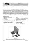
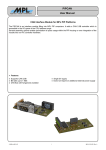
MCDISK-E
USER'S MANUAL
High-Tech Made in Switzerland
PCMCIA/JEIDA CARD READER/WRITER WITH SCSI INTERFACE
The MCDISK-E (Memory Card Disk) is a two slot card reader/writer for PCMCIA/JEIDA compatible memory cards. Two card
slots allow for simultaneous use of memory cards. The MCDISK-E can handle a wide variety of cards of any size: SRAM, ROM,
OTP, E(E)PROM, FLASH, I/O and PC-ATA disks. To interface those cards to the host equipment it has an SCSI interface. The
SCSI interface is widely used for connecting mass storage devices like hard disks to microcomputers.
A memory card can be thought of as an extremely fast disk storage device, because there are no latencies for moving
mechanical parts like read/write heads. In all other aspects however, a disk device and a memory card are much the same.
The MCDISK-E exists in two versions. The first one is equivalent to a 3.5" Floppy drive which can be easily incorporated into
OEM products. The second one is a desktop case with built-in power supply for easy connection to all computers with a SCSI
interface. However, although the reader/writer device is compact and economically priced, no concessions have been made
in its performance. It provides a fully professional yet highly economic solution to demands for data storage in harsh
environment. This makes the MCDISK-E ideal for use in many industrial and business applications with SCSI data input and/
or output.
TECHNICAL FEATURES
• Memory card types I, II and III are supported
• Supports direct access to entire memory card (raw access)
• Hybrid card (mixed memory types) and multiple partition
support
• All PCMCIA operations handled automatically by the unit
• Built-in socket and card services feature transparent access
to card data for PCMCIA-unaware host systems
• High data security through block check capability
• Local 68HC11 processor
• SCSI-2 interface with a WD 33C93 SCSI controller
• Standard SCSI command set
• Low power consumption, typ. 120mA (no card inserted)
• Fast 2 Mbytes/s transfer rate
• Size and mounting compatible to 3.5" floppy disk drive
(open-frame with 1” height) for MCDISK-E-1
• Desktop case for horizontal or vertical mounting
for MCDISK-E-5
• Interfaces PCMCIA/JEIDA Memory Cards to any system
with a SCSI interface
• Double card slot
• Separate SCSI ID for each slot can be configured
• SRAM, ROM, OTP, E(E)PROM, FLASH and I/O card support
• PC-ATA disk support
• Card sizes 512 Byte up to 64 MByte (PC-ATA: 4 GByte)
• Powerless card inserting of PCMCIA cards
References :
MCDISK-E-1 Open frame Reader/Writer for JEIDA/PCMCIA Memory Cards +5V / +12VDC
MCDISK-E-5 Desktop case Reader/Writer for JEIDA/PCMCIA Cards 100-240VAC / 50-60 Hz
© 1997 by MPL AG
1
MEH-10000-003 Rev. H
MCDISK-E
High-Tech Made in Switzerland
TABLE OF CONTENTS
INTRODUCTION ................................................................................................................................................................... 3
I. ABOUT THIS MANUAL ............................................................................................................................................ 3
II. SAFETY PRECAUTIONS AND HANDLING ........................................................................................................... 3
III. EQUIPMENT SAFETY ........................................................................................................................................... 3
1. COMMON FOR ALL MCDISK-E ........................................................................................................................................ 4
1.1 COMPATIBILITY ................................................................................................................................................... 4
1.2 OPERATION ......................................................................................................................................................... 4
1.3 PCMCIA CARD TYPES ........................................................................................................................................ 4
1.4 CARD HANDLING ............................................................................................................................................... 4
1.4.1 INSERTING A CARD ............................................................................................................................. 4
1.4.2 EJECTING A CARD ............................................................................................................................... 5
1.5 LED INDICATORS ............................................................................................................................................... 5
1.5.1 BASIC INDICATIONS ............................................................................................................................. 5
1.5.2 ERROR SIGNALLING ............................................................................................................................ 5
1.6 DRIVER SOFTWARE ........................................................................................................................................... 5
2. MCDISK-E-1 OPEN FRAME .............................................................................................................................................. 6
2.1 SPECIFICATIONS ................................................................................................................................................ 6
2.1.1 PHYSICAL DIMENSIONS ...................................................................................................................... 6
2.2 ELECTROSTATIC DISCHARGE (ESD) PROTECTION ...................................................................................... 6
2.3 SET-UP ................................................................................................................................................................. 7
2.3.1 SET-UP OVERVIEW .............................................................................................................................. 7
2.3.2 PARTS LOCATIONS .............................................................................................................................. 7
2.4 SCSI ID AND OPTIONAL FEATURES ................................................................................................................. 8
2.4.1 SCSI ID ................................................................................................................................................... 8
2.4.2 DUAL SCSI ID FEATURE ...................................................................................................................... 8
2.4.3 OPTIONAL FEATURES ......................................................................................................................... 8
2.5 TERMINATION ..................................................................................................................................................... 8
2.5.1 SCSI BUS TERMINATION ..................................................................................................................... 8
2.5.2 TERMINATOR POWER (TERMPWR) ................................................................................................... 8
2.6 MOUNTING .......................................................................................................................................................... 9
2.6.1 GENERAL HINTS .................................................................................................................................. 9
2.6.2 HARDWARE REQUIRED ...................................................................................................................... 9
2.6.3 MOUNTING THE UNIT ........................................................................................................................... 9
2.7 POWER AND SCSI BUS CONNECTION ........................................................................................................... 10
2.7.1 SCSI BUS CONNECTION ................................................................................................................... 10
2.7.2 SCSI Chain .......................................................................................................................................... 10
2.7.3 POWER CONNECTION ....................................................................................................................... 10
2.8 DC VOLTAGE MONITOR ................................................................................................................................... 10
2.9 MECHANICAL DIMENSIONS ............................................................................................................................ 11
3.MCDISK-E-5 DESKTOP VERSION .................................................................................................................................. 12
3.1 SPECIFICATIONS .............................................................................................................................................. 12
3.1.1 PHYSICAL DIMENSIONS .................................................................................................................... 12
3.2 RADIO AND TELEVISION INTERFERENCE ..................................................................................................... 12
3.3 SET-UP ............................................................................................................................................................... 13
3.3.1 SET-UP OVERVIEW ............................................................................................................................ 13
3.3.2 PARTS LOCATIONS ............................................................................................................................ 13
3.3.3 SCSI ID ................................................................................................................................................. 13
3.4 TERMINATION ................................................................................................................................................... 13
3.4.1 SCSI BUS TERMINATION ................................................................................................................... 13
3.5 OPTIONAL FEATURES ...................................................................................................................................... 13
3.6 MECHANICAL DIMENSIONS ............................................................................................................................ 13
DISCLAIMER ....................................................................................................................................................................... 16
2
MCDISK-E
High-Tech Made in Switzerland
INTRODUCTION
•
I. ABOUT THIS MANUAL
For your protection and that of your MCDISK disconnect the
power input immediately if any of the following conditions
exists:
This manual is written for use by technical personnel responsible for integrating the MCDISK-E reader/writer into their
system. The manual assists the installation procedure by
providing the information necessary to handle, configure and
mount the MCDISK-E reader/writer.
The MCDISK-E reader/writer is designed to work with most
host systems which are fitted with an SCSI interface. It is a
simple procedure to set up the unit, nevertheless, before
attempting any installation, please read through all applicable
sections of this manual and follow the instructions herein.
•
•
For personal safety and safe operation of the MCDISK-E,
follow all safety procedures described here and in other
sections of the manual.
•
Handle the unit carefully, i.e. dropping or mishandling the
read/write unit can cause damage to internal assemblies.
•
Read and follow all the instructions and warnings described herein.
•
Keep the MCDISK away from all sources of liquids, such
as coffee cups, drinking glasses, washing facilities etc.
•
Protect the MCDISK from damp or wet weather.
•
Something has been spilt onto the case.
•
The MCDISK has been damaged in any way, e.g. through
dropping.
•
The MCDISK has been exposed to excess moisture or
rain.
•
You suspect that the unit requires servicing or repair.
Great care is taken by MPL that all it's products are thoroughly
and rigorously tested before leaving the factory to ensure that
they are fully operational and conform to specification. However, no matter how reliable a product, there is always the
remote possibility that a defect may occur. The occurrence of
a defect on this device may, under certain conditions, cause
a defect to occur in adjoining and/or connected equipment. It
is the users responsibility to ensure that adequate protection
for such equipment is incorporated when installing this
device. MPL accepts no responsibility whatsoever for such
kind of defects, however caused.
II. SAFETY PRECAUTIONS AND HANDLING
Power must be removed from the computer system before
installing (or removing) the MCDISK-E reader/writer to
prevent the possibility of personal injury (electrical shock!)
and/or damage to the unit.
The power input cable has been damaged.
III. EQUIPMENT SAFETY
MCDISK Technical Reference Manual (supplied by MPL
AG or your local MCDISK supplier). The MCDISK Technical Reference Manual is also available on the internet
under "http://www.mpl.ch" in PDF format.
PCMCIA PC Card Standard (July 1993, Release 2.1)
ANSI SCSI-2 Standard (X3.131-199x, Revision 10h)
•
•
WARNING: There are no user-serviceable components on the MCDISK-E!
The following publications relate closely to this product and
supply information about PCMCIA and SCSI interface. For
those involved in writing drivers or special applications that
directly interface to the MCDISK-E, a Technical Reference
Manual provides information required to drive the MCDISK-E
on the SCSI command level.
•
Keep this manual available for reference.
3
MCDISK-E
High-Tech Made in Switzerland
1. COMMON FOR ALL MCDISK-E
1.4 CARD HANDLING
1.1 COMPATIBILITY
Follow the instructions as described in this section when
inserting and ejecting PCMCIA cards. Refer to Figure 5 to
locate indicated items.
MCDISK-E operates with various system platforms using
standard driver software. Some host systems do not fully
support MCDISK-E and require special driver software. MPL
AG provides a "Technical Note for MCDISK" that reflects the
actual status of software support for different host systems.
Additionally, this Technical Note lists PCMCIA card type
compatibility tests performed by MPL AG or MCDISK users.
1.4.1 INSERTING A CARD
When inserting a card into one of the card slots of the MCDISKE, care must be taken to ensure that the card is inserted
correctly. Follow these steps to insert the card:
1. Orientate the memory card so that the printed surface (e.g.
with manufacturer name/logo) is up and the 68-pin connector points towards the MCDISK-E card slot. Note that
some cards have an arrow indicating direction of insertion.
1.2 OPERATION
This chapter provides information about the use of the
PCMCIA cards and the LED indicators.
The illustration below identifies the items visible on the front
panel of the MCDISK-E.
Upper card
eject button
2. Insert the card into the slot. It should slide easily into the
slot until approx. 15 mm remain exposed and the card
comes to a soft stop. At this point gentle pressure is
required to make the final connection between the
memory card and the card slot connector.
If the card comes to a sudden stop earlier than described
above, do not press any further! Key guides on the card
and in the card slot ensure that the card cannot be fully
inserted (does not reach the connector) when inserted in
the wrong way! Remove the card, check orientation and
try again.
Lower card
eject button
Power LED
(green)
Access LED
upper slot
Error LED
(red)
Access LED
lower slot
Fig.1.2: Front view
1.3 PCMCIA CARD TYPES
The MCDISK-E has been designed to accept three different
PCMCIA card types:
•
•
•
3. When the card is fully inserted a small portion of the card
will remain exposed from the card slot opening. The red
LED on the front of the MCDISK-E will go off indicating that
the card is present. If the red LED remains lit then the card
has not been inserted correctly or cannot be operated by
the MCDISK-E (e.g. bad card type).
Type I: Thickness 3.3 mm, no raised substrate area
Type II: Thickness 5.0 mm, 48 mm wide raised substrate
area
Type III: Thickness 10.5 mm, 51 mm wide raised
substrate area
WARNING: Do NOT use excessive force to overcome any resistance when inserting the card. This
should not be necessary and will severely damage
both the card and the MCDISK-E.
The lower card slot accepts all three types of cards. Due to the
front panel cutout, the upper card slot only accepts type I and
II cards.
Type I and II cards can be inserted simultaneously in the lower
and upper slot. Type III cards must be inserted in the lower
slot, likewise occupying the space of the upper slot.
4
MCDISK-E
High-Tech Made in Switzerland
1.4.2 EJECTING A CARD
1.5.2 ERROR SIGNALLING
Each card slot has its own card eject button. The eject button
at the left hand side of the card slots serves the upper card slot,
the eject button on the right hand side the lower card slot.
Arrows are printed on the eject buttons that point to the card
slot they serve.
In case of an error, the red and both yellow indicators will show
a diagnostic status:
•
All three indicators remain unlit: Ensure that the unit is
connected correctly to a powered SCSI bus. Likewise the
unit cannot start-up when the SCSI bus is not or not
correctly terminated (TERMPWR OK?). If the SCSI bus is
okay and the indicators still remain unlit, there may be a
hardware problem and the unit requires service.
•
All three indicators flash only once and then remain unlit:
The internal RAM test has failed. The unit requires service.
•
The error LED flashes repeatedly: There is a SCSI hardware problem.
•
The error LED double-flashes repeatedly: This indicates a
severe SCSI bus protocol error that prevents the MCDISK from continuing SCSI operation. The MC-DISK
needs to be reset to recover from this error. If the error is
permanent, check SCSI cabling, terminators and SCSI
ID's.
•
The error LED triple-flashes repeatedly: The ROM contents are not okay. The unit requires service.
•
The LEDs show some other pattern than those listed
above: There is a serious hardware problem, and the unit
needs to be returned to your local MCDISK-E supplier for
repair.
To remove the PCMCIA card push the corresponding eject
button. The card is released from the connector inside and it
may now be pulled free.
CAUTION: Do NOT attempt to pull the card free without first
pressing the card eject button!
Do NOT attempt to remove the card when the yellow LED is
lit (see also next section)!
WARNING: Avoid the situation where foreign objects, dust,
liquids etc. can enter the MCDISK-E through the card slot
opening. This can cause severe damage.
1.5 LED INDICATORS
The MCDISK-E is equipped with four LED indicators. Refer
to Figure 1.2 for the location of the indicators.
1.5.1 BASIC INDICATIONS
The green LED (upper left hand side) is the power indicator.
It is lit whenever the unit is turned on.
The yellow (right hand side) LEDs are the access indicators
for the upper and lower slot. They are illuminated whenever
an access to the memory card in the corresponding slot takes
place.
1.6 DRIVER SOFTWARE
If your MCDISK supplier has provided a driver software
package with your MCDISK-E, this must be loaded on the host
computer before commencing to work with the MCDISK-E.
Follow the instructions provided with the driver and/or the
procedures laid down for installing software on the host
computer provided in the host computer documentation.
If you have an Internet access you can visit our Web site at
Don’t eject the PCMCIA card when the yellow LED is lit!
The red (left hand side) LED is the status indicator. It is
illuminated when the MCDISK-E is not operable due to one
of the following reasons:
•
•
There is no card inserted. If a card is inserted correctly, the
red LED will go off.
http://www.mpl.ch
There is a card inserted, but it cannot be accessed by the
MCDISK-E. Such errors can have various causes: the unit
is attempting to write to a write-protected or read-only
card, unknown I/O card, hardware error on a memory card,
etc.
There you will find different tools, drivers and additional
documentation especially for MCDISKs.
During start-up (power up or SCSI bus reset), the MCDISKE performs some internal self tests. When everything is okay,
the red and both yellow indicators will flash twice simultaneously to indicate proper start-up and proper SCSI connection.
5
MCDISK-E
High-Tech Made in Switzerland
2.2 ELECTROSTATIC DISCHARGE (ESD) PROTECTION
2. MCDISK-E-1 OPEN FRAME
2.1 SPECIFICATIONS
Performance:
Transfer rate
Average throughput
with SRAM card
Latency
2.0 MByte/sec
0 ms
Interfaces:
SCSI standard
SCSI bus connector
SCSI bus configuration
PCMCIA standard
PCMCIA card slots
PCMCIA card types
SCSI-2
50-pin/male ribbon
8-bit/single-ended
Release 2.1
2
Type I - III
Various electrical components within the read/write unit are
sensitive to static and electrostatic discharge (ESD). Even a
non-sensible static discharge can be sufficient to destroy or
degrade a component's operation.
2.5 MByte/sec
Following the precautions listed below will avoid ESDrelated problems:
Power Requirements (without card):
+5 VDC (+/- 5%)
120 mA
+12 VDC (+/- 5%)
depends on card, min. 1mA
Use a properly installed antistatic pad on your work
surface.
•
Wear wrist straps and observe proper ESD grounding
techniques.
•
Leave the unit in its antistatic cover until you are prepared
to install it in the system. When it is out of its protective
cover, place the unit on the properly grounded antistatic
work surface pad.
Do not touch any components on the read/write unit.
Handle or touch only the unit chassis.
Operating Environment:
Temperature
0°C ... 70°C
Extended temp. (opt.)
-25°C ... +70°C
Relative humidity
(non-condensing)
10% ... 90%
2.1.1 PHYSICAL DIMENSIONS
Height
Width
Lenght
Front panel thickness
Weight
•
25.4 mm (1.0")
101 mm (4.0")
145 mm (5.75")
3.0 mm (0.12")
0.25 kg (0.55 lbs)
6
MCDISK-E
High-Tech Made in Switzerland
2.3 SET-UP
2.3.2 PARTS LOCATIONS
This chapter provides the information required to configure
the MCDISK-E reader/writer. It describes the setting of the
SCSI ID, local features and configuring the SCSI termination
characteristics.
If you have any doubts on configuration, contact your
MCDISK-E supplier or an authorized dealer of your host
computer.
The following figures show the location of the configuration
jumper, connectors, termination resistors as well as a view of
the front panel with its indicator LEDs.
&
&
&
&
&
5
5
5
5
5
&
&
&
&
5
5
/
/
'
'
&
&
&
&
&
&
&
5
5
&
-
&
&
8
5
5
5
5
&
&
7 7
3 3
7
Set-up of MCDISK-E-1 is a step by step procedure:
7
5 5
5
5
5
5
1. Remove the drive from its packing and place it on an
appropriate antistatic work surface, following the ESD
precautions described in the beginning of this manual.
8
8
5
5
5
5
&
7
)
2.3.1 SET-UP OVERVIEW
8
&
&
5 5 7
'
7
7
5 5
& '
J2: SCSI ID and
optional features
WARNING: Before you begin, review and observe
the safety precautions described at the beginning of
this manual to avoid personal injury or damage to
equipment.
5 5 5 5
&
&
5
& 5 5
&
&
8
5
5
&
7
2. Set the unit’s SCSI ID and optional features.
& 5 5
5
&
3. Terminate the SCSI bus if required.
4. Mount the unit in the system (see chapter 2.6).
5 5
5
&
&
&
5
5 5 5 5
& 5
5. Connect DC power and SCSI bus to the unit (see chapter
2.5).
&
&
SCSI ID = 3
Parity disabled
Single SCSI ID
Full CIS mode
Termination enabled
Termpower enabled
)
&
&
'
5
5
5 5 5
7
-
&
5
5
&
J8: SCSI termination
& termination power
&
5 5
&
7
5 5 5 & 5 5 5
The default factory settings are as follows:
•
•
•
•
•
•
5
5
&
&
& &
& &
&
&
&
&
J3: SCSI connector
'
J6: Power
connector
Fig. 2.3.2.A: Parts location
Upper card
eject button
Lower card
eject button
Power LED
(green)
Access LED
upper slot
Error LED
(red)
Access LED
lower slot
Fig. 2.3.2.B: Front view
7
MCDISK-E
High-Tech Made in Switzerland
2.4 SCSI ID AND OPTIONAL FEATURES
2.4.3 OPTIONAL FEATURES
The configuration jumper (J2, refer to figure 2.3.2.A) selects
the SCSI ID and the optional features SCSI parity and CIS
mode. Note that one jumper position is reserved and must be
left open!
0
Reserved, leave open!
Two optional features can be configured at J2: SCSI parity
and CIS mode (refer to figure 2.3).
The SCSI parity configuration of the MCDISK-E should match
that of the host computer. Check the host computer documentation to verify its setting. On delivery, the MCDISK-E’s parity
is disabled which should be OK for most system integrations.
The parity can be enabled by installing a jumper across the
referenced pins.
PCMCIA/JEIDA cards supporting CIS (Card Information
Structure) can be automatically identified by the MCDISK-E.
On delivery, CIS mode 00 (both jumpers not installed) is set
and should not need to be changed. Very special applications
might require a different CIS mode. In such a case, refer to the
corresponding sections in the ‘MCDISK Technical Reference
Manual’ first.
J2
0 Single SCSI ID
1 Dual SCSI ID mode
0 0
Full CIS mode (default)
1 0
Suppress CIS Level 1 writing
0 1
No CIS formatting by default
1 1
No CIS recognition
16
1
9
8
0 0 0 SCSI ID 0
1 0 0 SCSI ID 1
0 1 0 SCSI ID 2
1 1 0 SCSI ID 3
0 0 1 SCSI ID 4
1 0 1 SCSI ID 5
0 1 1 SCSI ID 6
1 1 1 SCSI ID 7
'1' = Jumper installed
'0' = Jumper not installed
0
1
SCSI Parity disabled (default)
Parity enabled
2.5 TERMINATION
2.5.1 SCSI BUS TERMINATION
(Not recommended)
Both ends of the SCSI bus cable must be terminated. Generally, one end is terminated at the host computer. The other end
must be terminated by the last SCSI device on the SCSI bus.
Fig. 2.4: Configuration jumper
WARNING: Ensure that no more than two devices
on the SCSI bus are terminated. Otherwise serious
corruption of data and/or damage to the SCSI bus
devices may result!
2.4.1 SCSI ID
Each device on the SCSI bus must have a unique SCSI ID
number. The numbers range from 0 .. 7 which allows for a
maximum of eight SCSI devices on the bus. Before setting the
SCSI ID for MCDISK-E, an ID must be chosen that is not yet
used by other SCSI devices. Usually, most host computer
systems already use SCSI ID 0 (internal SCSI hard disk drive)
and SCSI ID 7 (host computer itself). Check the documentation of the host computer and the attached peripheral SCSI
devices to verify the available SCSI ID numbers.
When the MCDISK-E is the last device on the SCSI bus, it
must be terminated by installing pin 2-3 of jumper J8.
0 Termination off
1 Termination on
0 External TERMPWR
1 Internal TERMPWR
WARNING: Ensure that each SCSI device has a
unique SCSI ID number. If not, serious corruption of
data and/or failure of the host computer may result!
2
3
1
4
2.4.2 DUAL SCSI ID FEATURE
2.5.2 TERMINATOR POWER (TERMPWR)
Note that this feature is available with Firmware V3.3 and
newer only.
When J2 6-11 is closed, the MCDISK-E provides accessing
each slot through a separate SCSI ID. This is useful for
systems with standard SCSI driver software. When the Dual
SCSI feature is selected, the MCDISK-E occupies a second
SCSI ID which is one higher than the SCSI ID selected with
the jumpers (see chapter 2.3.1), but only if the selected ID is
less than 6. If the selected ID is 6 or 7, the Dual SCSI feature
is disabled.
Generally, the host computer is the only device on the SCSI
bus required to provide termination power for the bus. In
special cases like some notebooks it's neccessary to supply
the termination power via a peripheral device. If the MCDISKE is jumpered correctly, it can be used to supply the termination power to the SCSI bus.
8
MCDISK-E
High-Tech Made in Switzerland
The MCDISK-E contains internal components to provide
Active Termination of the SCSI bus. Compared to Passive
Termination, Active Termination is far less sensitive to
TERMPWR voltage variations, which, amongst other things,
increases data security.
Figure 2.5.2 shows the terminator circuit as used on the
MCDISK-E:
2.6.1 GENERAL HINTS
You can mount the MCDISK-E in any position. The read/write
unit's placement must permit sufficient airflow to ensure that
it operates within the environmental limits listed in Chapter 1
under 'Specifications'.
Depending upon your specific system, you may wish to attach
the power and SCSI cable before mounting the unit in the
system. In such a case, read Chapter 2.8 first.
Vcc MCDISK
5.0V
1
4
2
3
2.6.2 HARDWARE REQUIRED
To all 18
SCSI lines
The MCDISK-E-1 can be installed in a 3.5" bay or any custom
manufactured support with only four M3 screws. Typically,
screw length is 6 mm, but can vary depending upon enclosure
or support thickness.
Termination
To SCSI connector
CAUTION: Ensure that screws used to mount the
read/write unit do not extend beyond the frame into
the PCB cavity, otherwise damage to the PCB may
result.
Figure 2.5.2: Active termination
If the MCDISK is the only device with an active termination, it
is recommended to connect it at the end of the chain.
2.6.3 MOUNTING THE UNIT
The MCDISK-E is equivalent (in size and mounting) to a
standard 3.5" slim-line floppy disk drive. In most cases, this
simplifies the installation of the read/write unit. To mount the
unit:
2.6 MOUNTING
This chapter provides the procedure for mounting and fixing
the read/write unit.
WARNING: Before commencing, verify that the host
system is switched off and disconnected from the
mains power. Review and observe the safety precautions described at the beginning of this manual
to avoid personal injury or damage to equipment.
9
•
Position the unit in the 3.5" bay (and the enclosure cutout)
and gently move it until the four screw holes are aligned.
•
Insert and secure the screws at these locations.
MCDISK-E
High-Tech Made in Switzerland
2.7 POWER AND SCSI BUS CONNECTION
2.8 DC VOLTAGE MONITOR
This chapter provides directions for connecting the SCSI bus
cable and the power cable to the MCDISK-E.
The MCDISK-E monitors the voltage level of the +5 VDC
supply. The unit resets/runs at the following voltage levels:
WARNING: Before you begin, review and observe
the safety precautions described at the beginning
of this manual to avoid personal injury or damage
to equipment.
4.70 VDC:
4.45 VDC:
2.7.1 SCSI BUS CONNECTION
The SCSI bus connector J3 is located at the rear of the unit.
It accepts 50-pin flat ribbon cables with a standard female
connector. When connecting the SCSI bus cable to connector
J3, carefully align both connectors to avoid bending or damaging the connector pins.
J3: SCSI
49
J6: Power
connector
1
2
50
connector
+12V
+5V
GND
Fig. 2.7.1: Rear view
2.7.2 SCSI Chain
The following figure shows a typical SCSI connections.
SCSI Bus
Internal HD
ID 0
MCDISK-E
ID 1-6
SCSI Controller
ID 7
Fig. 2.7.2 SCSI chain
2.7.3 POWER CONNECTION
The MCDISK requires a power input of +5 VDC (+/- 5% , typ.
120mA) and +12VDC (±5%, min. 1mA). When providing
power for the unit, take into account the additional current
consumption of the cards to be used!
The power connector J6 is located at the rear of the unit. This
4-pin keyed connector accepts standard connectors of various manufacturers. The pin-out of connector J6 is shown in
Figure 2.7.1.
10
In power-up, the +5 VDC supply has to rise
above this level, otherwise MCDISK-E stays
reset and will not operate.
If the voltage drops below this level, the unit
resets.
MCDISK-E
High-Tech Made in Switzerland
2.9 MECHANICAL DIMENSIONS
25.4
Figure 3.4 shows the unit frame including front panel, with
mounting locations and dimensions indicated.
6.0
6.0
4
31.0
21.0
3
101.6
30.0
Material Aluminium 2mm
94
101.6
Thread M3
Fig.3.4: Mechanical dimensions
11
70.0
60.0
145.0
4
MCDISK-E
High-Tech Made in Switzerland
3.2 RADIO AND TELEVISION INTERFERENCE
3.MCDISK-E-5 DESKTOP VERSION
3.1 SPECIFICATIONS
Performance:
Transfer rate
Average throughput
with SRAM card
Latency
Interfaces:
SCSI standard
SCSI connectors
SCSI bus connectors
connectors
SCSI bus configuration
PCMCIA standard
PCMCIA card slots
PCMCIA card types
2.5 MByte/sec
2.0 MByte/sec
0 ms
SCSI-2
2
50-pin
delta
ribbon
This equipment has been tested and found to comply with the
limits for a Class B digital device, pursuant to Part 15 of the
FCC rules. These limits are designed to provide reasonable
protection against harmful interference in a residential installation. This equipment generates, uses and can radiate radio
frequency energy and, if not installed and used in accordance
with the instructions, may cause harmful interference to radio
communications. However, there is no guarantee that interference will not occur in a particular installation. If this
equipment does cause harmful interference to radio or
television reception, which can be determined by turning the
equipment off and on, the user is encouraged to try to correct
the interference by one or more of the following measures:
•
Reorient or relocate the receiving antenna.
•
Increase the separation between the equipment and
receiver.
•
Connect the equipment into an outlet on a circuit
different from that which the receiver is connected.
Power Requirements
100-240VAC / 15W max. 50-60 Hz.
•
Consult the dealer or an experienced radio/TV technician for help.
Operating Environment:
Temperature
0°C ... 70°C
Relative humidity
(non-condensing)
10% ... 90%
Shielded cables and I/O cords must be used for this equipment to comply with the relevant FCC and CE regulations.
8-bit/single-ended
Release 2.1
2
Type I - III
3.1.1 PHYSICAL DIMENSIONS
Height
Width
Lenght
Weight
56 mm (1.42")
179 mm (4.32")
215 mm (5.46")
0.43 kg (0.95 lbs)
This equipment has also been tested for CE conformity. It
complies to the following standards:
•
EN 55022: 1994 (Class B)
•
•
•
•
EN 50082-1: 1992
IEC 1000-4-2: 1995
IEC 1000-4-3: 1995 (incl. ENV 50204)
IEC 1000-4-4: 1995
Changes or modifications not expressly approved in writing
by MPL AG may void the user's authority to operate this
equipment.
12
MCDISK-E
High-Tech Made in Switzerland
3.3 SET-UP
SCSI ID
Switch
This chapter provides the information required to configure
the MCDISK-E reader/writer. It describes the setting of the
SCSI ID and configuring the SCSI termination.
If you have any doubts on configuration, contact your
MCDISK-E supplier or an authorized dealer of your host
computer.
WARNING: Before you begin, review and observe
the safety precautions described at the beginning of
this manual to avoid personal injury or damage to
equipment.
SCSI
Connectors
90-264VAC
Power plug
3.3.1 SET-UP OVERVIEW
Set-up of MCDISK-E-5 is a step by step procedure:
3.3.3 SCSI ID
1. Remove the drive from its packing.
2. Set the unit’s SCSI ID (see chapter 3.3.3).
3. Terminate the SCSI bus if required (see chapter 3.4).
4. Connect the unit to the host computer
5. Connect the AC power and switch the unit on.
In the desktop case only the SCSI ID is available via a
pushwheel on the rear panel. Through simple pressing with
a pencil or something similar on the + or - button the SCSI ID
can be changed. All other changes or features must be done
the same way as in the open frame case. Please refer to
chapters 2.3 and 2.4 for detailed information.
The default factory settings are as follows:
•
•
•
•
•
•
SCSI ID = 3
Parity disabled
Single SCSI ID
Full CIS mode
Termination enabled
Termpower enabled
3.4 TERMINATION
3.4.1 SCSI BUS TERMINATION
Both ends of the SCSI bus cable must be terminated. Generally, one end is terminated at the host computer. The other end
must be terminated by the last SCSI device on the SCSI bus.
3.3.2 PARTS LOCATIONS
56 mm
The following figures shows the location of the SCSI ID
pushwheel, power supply and SCSI connector as well as a
view of the front with the power switch, the LEDs and the card
slot.
Power LED
Lower card
eject button
Access LED
upper slot
When the MCDISK-G-5 is the last device on the SCSI bus, it
must be terminated by installing a terminator on one SCSI
connector or by installing the corresponding jumper in the
device. For a detailed description refer to chapter 2.5.1 "SCSI
bus termination" (open frame version).
21
5
m
m
Upper card
eject button
WARNING: Ensure that no more than two devices
on the SCSI bus are terminated. Otherwise serious
corruption of data and/or damage to the SCSI bus
devices may result!
Card slots
All optional features like Dual SCSI, special CIS mode and
SCSI parity must be done the same way as in the open frame
version. Please refer to chapter 2.4.
170 mm
Error LED
Access LED
lower slot
3.5 OPTIONAL FEATURES
Power LED
Power switch
3.6 MECHANICAL DIMENSIONS
Please refer to chapter 3.3.2 "Parts Location" .
13
MCDISK-E
High-Tech Made in Switzerland
This page is intentionally left blank
14
MCDISK-E
High-Tech Made in Switzerland
This page is intentionally left blank
15
MCDISK-E
High-Tech Made in Switzerland
COPYRIGHT AND REVISION HISTORY
Copyright © 1997 by MPL AG Elektronikunternehmen. All
Rights Reserved. Reproduction of this document in part or
whole, by any means is prohibited, without written permission
from MPL AG Elektronikunternehmen.
This manual reflects the revision D of the MCDISK-E
Publication Date : October 1997
DISCLAIMER
All implied warranties on the product and manuals, including
implied warranties of merchantability and fitness for a particular purpose, are limited in duration to twelve (12) months from
the date of the original retail purchase of this product.
MPL has fully tested the MCDISK and reviewed the documentation. However, MPL makes no warranty or representation,
either expressed, or implied, with respect to this product, its
quality, performance, merchantability, or fitness for a particular purpose.
In no event will MPL be liable for direct, indirect, special,
incidental, or consequential damages resulting from any
defect in the product or its documentation, even if advised of
the possibility of such damages. In particular MPL shall have
no liability for any programs or data stored in or used with this
product, including the costs of recovering such programs or
data.
MPL AG reserves the right to make changes to any product
herein to improve reliability, function or design.
MCDISK is a trademark of MPL AG Elektronikunternehmen.
Our local distributor:
0494
16
Printed in Switzerland