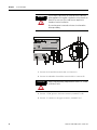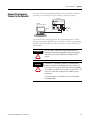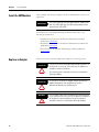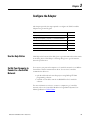
1
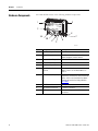
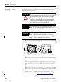
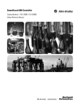
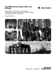
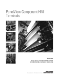
User Manual
XM ControlNet Adapter
Catalog Number 1440-ACNR
Important User Information
Solid state equipment has operational characteristics differing from those of electromechanical equipment. Safety Guidelines for
the Application, Installation and Maintenance of Solid State Controls (publication SGI-1.1 available from your local Rockwell
Automation sales office or online at http://www.rockwellautomation.com/literature) describes some important differences
between solid state equipment and hard-wired electromechanical devices. Because of this difference, and also because of the wide
variety of uses for solid state equipment, all persons responsible for applying this equipment must satisfy themselves that each
intended application of this equipment is acceptable.
In no event will Rockwell Automation, Inc. be responsible or liable for indirect or consequential damages resulting from the use or
application of this equipment.
The examples and diagrams in this manual are included solely for illustrative purposes. Because of the many variables and
requirements associated with any particular installation, Rockwell Automation, Inc. cannot assume responsibility or liability for
actual use based on the examples and diagrams.
No patent liability is assumed by Rockwell Automation, Inc. with respect to use of information, circuits, equipment, or software
described in this manual.
Reproduction of the contents of this manual, in whole or in part, without written permission of Rockwell Automation, Inc., is
prohibited.
Throughout this manual, when necessary, we use notes to make you aware of safety considerations.
WARNING
IMPORTANT
ATTENTION
Identifies information about practices or circumstances that can cause an explosion in a
hazardous environment, which may lead to personal injury or death, property damage, or
economic loss.
Identifies information that is critical for successful application and understanding of the
product.
Identifies information about practices or circumstances that can lead to personal injury
or death, property damage, or economic loss. Attentions help you identify a hazard,
avoid a hazard, and recognize the consequence
SHOCK HAZARD
Labels may be on or inside the equipment, for example, a drive or motor, to alert people
that dangerous voltage may be present.
BURN HAZARD
Labels may be on or inside the equipment, for example, a drive or motor, to alert people
that surfaces may reach dangerous temperatures.
Allen-Bradley, Rockwell Software, Rockwell Automation, XM, ControlLogix, Logix5000, RSLogix, RSNetWorx, and TechConnect are trademarks of Rockwell Automation, Inc.
Trademarks not belonging to Rockwell Automation are property of their respective companies.
2
Rockwell Automation Publication ICM-UM001C-EN-E - March 2013
Table of Contents
Preface
What This Preface Contains . . . . . . . . . . . . . . . . . . . . . . . . . . . . . . . . . . 5
Who Should Use This Manual. . . . . . . . . . . . . . . . . . . . . . . . . . . . . . . . . 5
Common Techniques Used in This Manual . . . . . . . . . . . . . . . . . . . . . . 5
Additional Resources . . . . . . . . . . . . . . . . . . . . . . . . . . . . . . . . . . . . . . . . 5
Chapter 1
Introduction
About the Module . . . . . . . . . . . . . . . . . . . . . . . . . . . . . . . . . . . . . . . . . . 7
Hardware Components . . . . . . . . . . . . . . . . . . . . . . . . . . . . . . . . . . . . . . 8
Chapter 2
Install the Adapter
North American Hazardous Location Approval . . . . . . . . . . . . . . 11
European Hazardous Location Approval. . . . . . . . . . . . . . . . . . . . 12
Power Requirements . . . . . . . . . . . . . . . . . . . . . . . . . . . . . . . . . . . . . . . 13
Terminating Resistors . . . . . . . . . . . . . . . . . . . . . . . . . . . . . . . . . . . . . . 13
Install the Adapter . . . . . . . . . . . . . . . . . . . . . . . . . . . . . . . . . . . . . . . . . 14
Panel/Wall Mounting . . . . . . . . . . . . . . . . . . . . . . . . . . . . . . . . . . . 15
Set the Node Address . . . . . . . . . . . . . . . . . . . . . . . . . . . . . . . . . . . . . . 15
Wire the Adapter . . . . . . . . . . . . . . . . . . . . . . . . . . . . . . . . . . . . . . . . . . 15
Connect Programming Terminal to the Network . . . . . . . . . . . . . . . . 17
Install the XM Modules . . . . . . . . . . . . . . . . . . . . . . . . . . . . . . . . . . . . . 18
Replace an Adapter . . . . . . . . . . . . . . . . . . . . . . . . . . . . . . . . . . . . . . . . 18
Remove Existing Adapter . . . . . . . . . . . . . . . . . . . . . . . . . . . . . . . . 19
Install Replacement Adapter . . . . . . . . . . . . . . . . . . . . . . . . . . . . . . 19
Chapter 3
Configure the Adapter
3Publication ICM-UM001C-EN-E - March 2013
Use the Help Button . . . . . . . . . . . . . . . . . . . . . . . . . . . . . . . . . . . . . . . 21
Set Up Your Computer to Connect to a ControlNet Network . . . . . . 21
Add Modules to the I/O Configuration . . . . . . . . . . . . . . . . . . . . . . . . 22
Select a Controller . . . . . . . . . . . . . . . . . . . . . . . . . . . . . . . . . . . . . . 22
Select a ControlNet Bridge . . . . . . . . . . . . . . . . . . . . . . . . . . . . . . . 23
Add the 1440-ACNR Adapter . . . . . . . . . . . . . . . . . . . . . . . . . . . . 26
Add XM Modules . . . . . . . . . . . . . . . . . . . . . . . . . . . . . . . . . . . . . . 29
Download the Program to the Controller. . . . . . . . . . . . . . . . . . . . . . . 32
Schedule the I/O Module Connections . . . . . . . . . . . . . . . . . . . . . . . . 33
Schedule the Network Online . . . . . . . . . . . . . . . . . . . . . . . . . . . . . 34
Reschedule a ControlNet Network That Has Previously Been
Scheduled . . . . . . . . . . . . . . . . . . . . . . . . . . . . . . . . . . . . . . . . . . . . . 37
Access Module Data using the ACNR . . . . . . . . . . . . . . . . . . . . . . . . . 39
3
Table of Contents
Chapter 4
Troubleshoot the Module
Status Indicators . . . . . . . . . . . . . . . . . . . . . . . . . . . . . . . . . . . . . . . . . . . 41
Module Status Indicator . . . . . . . . . . . . . . . . . . . . . . . . . . . . . . . . . 42
ControlNet A and ControlNet B Status Indicators Together . . . . 42
ControlNet A or ControlNet B Status Indicator Individually . . . 42
Backplane Status Indicator . . . . . . . . . . . . . . . . . . . . . . . . . . . . . . . 43
Index
. . . . . . . . . . . . . . . . . . . . . . . . . . . . . . . . . . . . . . . . . . . . . . . . . . . . . . . . . 45
4
Publication ICM-UM001C-EN-E - March 2013
Preface
What This Preface Contains
This preface describes how to use this manual.
Who Should Use This
Manual
This manual introduces you to the XM® ControlNet Adapter. It is intended
for anyone who installs, configures, or uses the XM ControlNet Adapter
module.
Common Techniques Used
in This Manual
There are several document conventions used in this manual, including the
following:
TIP
EXAMPLE
5Publication ICM-UM001C-EN-E - March 2013
A tip indicates additional information which may be helpful.
This convention presents an example.
5
Preface
Additional Resources
These documents contain additional information concerning related products
from Rockwell Automation.
Resource
Description
XM Monitoring Modules Specifications Provides specifications for the 1440 series of
Technical Data, publication 1440-TD001. Rockwell Automation monitoring modules.
XM ControlNet Adapter Installation
Instructions, publication ICM-IN001.
Provides information about installing the
adapter module and technical specifications.
Dynamic Measurement Module
Installation Instructions, publication
ICM-IN002
Provides information about mounting the
Dynamic Measurement module and technical
specifications.
Dynamic Measurement Terminal Base
Installation Instructions, publication
ICM-IN003
Provides information about installing the
terminal base for the Dynamic Measurement
module, and technical specifications.
Dynamic Measurement Module User
Manual, publication ICM-UM002
Provides details about how to install, wire and
use the Dynamic Measurement module.
Industrial Automation Wiring and
Grounding Guidelines, publication
1770-4.1
Provides general guidelines for installing a
Rockwell Automation industrial system.
ControlLogix System User Manual,
publication 1756-UM001
Describes how to use ControlNet with a
controller.
ControlNet Modules in Logix5000
Systems User Manual, publication
CNET-UM001
Provides information on how to connect a
computer to a ControlNet network
Product Certifications website,
http://ab.com
Provides declarations of conformity,
certificates, and other certification details.
You can view or download publications at
http://www.rockwellautomation.com/literature. To order paper copies of
technical documentation, contact your local Allen-Bradley distributor or
Rockwell Automation sales representative.
6
Publication ICM-UM001C-EN-E - March 2013
Chapter
1
Introduction
This chapter describes the XM ControlNet Adapter (Catalog Number
1440-ACNR).
About the Module
Topic
Page
About the Module
7
Hardware Components
8
The 1440-ACNR module operates as a communication adapter for the
1440-DYN02-01RJ module. It provides an interface for controlling this
module on an XM Bus and transferring data to the processor over a
ControlNet network.
The ControlNet network is a communication architecture that enables the
exchange of messages between ControlNet products compliant with the
ControlNet International specification. It provides high-speed transport of
time-critical I/O and interlocking data and messaging data, including
upload/download of programming and configuration data on a single physical
media link.
The module supports:
• Control of I/O on the XM Bus, with up to 10 XM Dynamic
Measurement modules (Cat. No. 1440-DYN02-01RJ) connected to the
adapter.
• Unscheduled messaging data for configuration and retrieval of data.
• Local communication network access through the network access port
(NAP).
7Publication ICM-UM001C-EN-E - March 2013
7
Chapter 1
Introduction
Hardware Components
The 1440-ACNR consists of the following hardware components.
9
1
XM®
Cont rolNet XM
Adapte
1440-ACNR
r
2
MS
CHA
CHB
BPS
8
3A
7
3B
4
5
6
31770-M
8
Item
Component
Description
1
ControlNet Adapter Module
2
Status Indicators
Four LEDs that indicate the status of the
adapter, backplane, and the network.
3A
Channel A Coax Receptacle
Channel A BNC connection.
3B
Channel B Coax Receptacle
Channel B BNC connection.
4
Module Locking tab
5
ControlNet Node Address
Switches
Pushwheel switches for setting the node
address. Refer to Set the Node Address on
page 15.
6
Network Access Port (NAP)
Provides a bidirectional electrical interface for
programming, maintenance, and I/O monitoring
devices. Refer to the ControlNet Coax Media
Planning and Installation Guide, publication
CNET-IN002.
7
24V DC Connections
+V DC power connections.
8
24V Common Connections
-V common connections.
9
XM Bus Connector
Connects the adapter to the XM modules on
the XM Bus.
Publication ICM-UM001C-EN-E - March 2013
Chapter
2
Install the Adapter
This chapter describes the procedures for installing the adapter.
9Publication ICM-UM001C-EN-E - March 2013
Topic
Page
Power Requirements
13
Terminating Resistors
13
Install the Adapter
14
Set the Node Address
15
Wire the Adapter
15
Connect Programming Terminal to the Network
17
Install the XM Modules
18
Replace an Adapter
18
9
Chapter 2
Install the Adapter
ATTENTION
Environment and Enclosure
This equipment is intended for use in a Pollution Degree 2
industrial environment, in overvoltage Category II applications
(as defined in IEC 60664-1), at altitudes up to 2000 m (6562 ft)
without derating.
This equipment is not intended for use in residential
environments and may not provide adequate protection to radio
communication services in such environments.
This equipment is supplied as open-type equipment. It must be
mounted within an enclosure that is suitably designed for those
specific environmental conditions that will be present and
appropriately designed to prevent personal injury resulting from
accessibility to live parts. The enclosure must have suitable
flame-retardant properties to prevent or minimize the spread of
flame, complying with a flame spread rating of 5VA or be
approved for the application if nonmetallic. The interior of the
enclosure must be accessible only by the use of a tool.
Subsequent sections of this publication may contain additional
information regarding specific enclosure type ratings that are
required to comply with certain product safety certifications.
In addition to this publication, see the following:
• Industrial Automation Wiring and Grounding Guidelines,
publication 1770-4.1, for additional installation
requirements.
• NEMA Standard 250 and IEC 60529, as applicable, for
explanations of the degrees of protection provided by
enclosures.
ATTENTION
Prevent Electrostatic Discharge
This equipment is sensitive to electrostatic discharge, which
can cause internal damage and affect normal operation. Follow
these guidelines when you handle this equipment:
•
•
•
•
•
•
10
Touch a grounded object to discharge potential static.
Wear an approved grounding wrist strap.
Do not touch connectors or pins on component boards.
Do not touch circuit components inside the equipment.
Use a static-safe workstation, if available.
Store the equipment in appropriate static-safe packaging
when not in use.
Publication ICM-UM001C-EN-E - March 2013
Install the Adapter
Chapter 2
North American Hazardous Location Approval
The following information applies
when operating this equipment in
hazardous locations.
Products marked "CL I, DIV 2, GP A, B, C, D"
are suitable for use in Class I Division 2
Groups A, B, C, D, Hazardous Locations and
nonhazardous locations only. Each product is
supplied with markings on the rating
nameplate indicating the hazardous location
temperature code. When combining
products within a system, the most adverse
temperature code (lowest "T" number) may
be used to help determine the overall
temperature code of the system.
Combinations of equipment in your system
are subject to investigation by the local
Authority Having Jurisdiction at the time of
installation.
WARNING
Explosion Hazard
Informations sur l’utilisation de cet
équipement en environnements
dangereux.
Les produits marqués "CL I, DIV 2, GP A, B, C,
D" ne conviennent qu'à une utilisation en
environnements de Classe I Division 2
Groupes A, B, C, D dangereux et non
dangereux. Chaque produit est livré avec des
marquages sur sa plaque d'identification qui
indiquent le code de température pour les
environnements dangereux. Lorsque plusieurs
produits sont combinés dans un système, le
code de température le plus défavorable
(code de température le plus faible) peut être
utilisé pour déterminer le code de
température global du système. Les
combinaisons d'équipements dans le système
sont sujettes à inspection par les autorités
locales qualifiées au moment de l'installation.
Risque d’Explosion
WARNING
• Do not disconnect
equipment unless
power has been
removed or the area
is known to be
nonhazardous.
• Couper le courant ou
s'assurer que
l'environnement est
classé non dangereux
avant de débrancher
l'équipement.
• Secure any external
connections that
mate to this
equipment by using
screws, sliding
latches, threaded
connectors, or other
means provided
with this product.
• Couper le courant ou
s'assurer que
l'environnement est
classé non dangereux
avant de débrancher
les connecteurs. Fixer
tous les connecteurs
externes reliés à cet
équipement à l'aide
de vis, loquets
coulissants,
connecteurs filetés
ou autres moyens
fournis avec ce
produit.
• Substitution of
components may
impair suitability for
Class I, Division 2.
• If this product
contains batteries,
they must only be
changed in an area
known to be
nonhazardous.
• La substitution de
composants peut
rendre cet
équipement inadapté
à une utilisation en
environnement de
Classe I, Division 2.
• S'assurer que
l'environnement est
classé non dangereux
avant de changer les
piles.
Publication ICM-UM001C-EN-E - March 2013
11
Chapter 2
Install the Adapter
European Hazardous Location Approval
The following applies when the product bears the Ex Marking.
This equipment is intended for use in potentially explosive atmospheres as defined
by European Union Directive 94/9/EC and has been found to comply with the
Essential Health and Safety Requirements relating to the design and construction
of Category 3 equipment intended for use in Zone 2 potentially explosive
atmospheres, given in Annex II to this Directive.
Compliance with the Essential Health and Safety Requirements has been assured
by compliance with EN 60079-15 and EN 60079-0.
ATTENTION
WARNING
This equipment is not resistant to sunlight or other sources of
UV radiation.
• This equipment must be installed in an enclosure providing at
least IP54 protection when applied in Zone 2 environments.
• This equipment must be used within its specified ratings
defined by Rockwell Automation.
• Provision must be made to prevent the rated voltage from
being exceeded by transient disturbances of more than 140%
of the rated voltage when applied in Zone 2 environments.
• This equipment must be used only with ATEX certified
backplanes.
• Secure any external connections that mate to this equipment
by using screws, sliding latches, threaded connectors, or other
means provided with this product.
• Do not disconnect equipment unless power has been removed
or the area is known to be nonhazardous.
• This equipment must be mounted in an ATEX certified
enclosure with a minimum ingress protection rating of at least
IP54 (as defined in IEC60529) and used in an environment of
not more than Pollution Degree 2 (as defined in IEC 60664-1)
when applied in Zone 2 environments. The enclosure must
utilize a tool removable cover or door.
12
Publication ICM-UM001C-EN-E - March 2013
Install the Adapter
Chapter 2
The ControlNet adapter module requires a single Class 2 power supply. Before
installing your module, calculate the power requirements of all modules in each
chassis. The total current draw through the side connector cannot exceed 3 A.
Power Requirements
The adapter provides a maximum output current of 3A.
ATTENTION
Multiple power sources are not allowed.
The XM Bus will operate correctly when there is a terminating resistor at each
end of the XM Bus.
Terminating Resistors
• Terminating resistors must be 121 ohms, 1%, 1/4 W.
• The ControlNet adapter has an internal terminating resistor. Install a
second terminating resistor across the CAN_HI and CAN_LO
terminals of the XM module at the other end of the XM Bus. For
information on the XM module, refer to the Dynamic Measurement
Module User Manual, publication ICM-UM002.
XM®
1
1
1
Class 2
XM BUS COMMON
CAN LOW
DRAIN WIRE
CAN HIGH
24 V
Supply
24 V COM
XM®
1
1
1
1
24 V
24 V COM
Publication ICM-UM001C-EN-E - March 2013
Termination
resistor
121 ohm, 1%,
1/4W
31865
13
Chapter 2
Install the Adapter
Install the Adapter
To install the adapter on the DIN rail prior to installing other XM terminal
base units, follow these steps.
This product is grounded through the DIN rail to chassis ground.
Use zinc plated yellow-chromate steel DIN rail to assure proper
grounding. The use of other DIN rail materials (for example,
aluminum or plastic) that can corrode, oxidize, or are poor
conductors, can result in improper or intermittent grounding.
Secure DIN rail to mounting surface approximately every 200
mm (7.8 in.) and use end-anchors appropriately.
ATTENTION
The 1440-DYN02-01RJ Dynamic Measurement module is used
with the 1440-ACNR. Any other XM catalog number will not
work with the 1440-ACNR.
IMPORTANT
The XM Bus must be terminated on each end with a 121 ohm,
1%, 1/4 W resistor. Because the adapter has an internal
terminator resistor, the second resistor must be connected to
the I/O module at the opposite end of the XM Bus.
IMPORTANT
1. Position the ControlNet adapter module (A) on a 35 x 7.5 mm DIN rail
(B) at a slight angle.
A
XM®
B
Cont rolNet XM
Adapter
1440-ACNR
Cont r olNet XM Adapter
XM®
1440-ACNR
MS
MS
CHA
CHB
CHA
CHB
BPS
BPS
C
31769-M
2. Hook the lip on the rear of the adapter onto the top of the DIN rail, and
rotate the adapter module onto the rail.
3. Press the adapter module down onto the DIN rail until flush. Locking
tab C will snap into position and lock the adapter module to the DIN
rail.
4. If the adapter module does not lock in place, use a screwdriver or similar
device to move the locking tab down while pressing the adapter module
flush onto the DIN rail, and release the locking tab to lock the adapter
module in place. If necessary, push up on the locking tab to lock.
5. Connect the adapter wiring. Refer to Wire the Adapter on page 15.
14
Publication ICM-UM001C-EN-E - March 2013
Install the Adapter
Chapter 2
Panel/Wall Mounting
If mounting the adapter to a panel or wall, refer to publication 1794-5.13,
"Panel Mounting Kit, Cat. No. 1794-NM1."
Set the Node Address
Set the node address using the 2-position pushwheel switch. Valid settings
range from 01 to 99.
Press either the + or - buttons to change the number.
2 5
Network
Address
Switch
Wire the Adapter
Follow these steps to wire the adapter.
ATTENTION
WARNING
Publication ICM-UM001C-EN-E - March 2013
Do not wire more than two conductors on any single terminal.
If you connect or disconnect wiring while the field-side power
is on, an electrical arc can occur. This could cause an explosion
in hazardous location installations. Be sure that power is
removed or the area is nonhazardous before proceeding.
15
Chapter 2
Install the Adapter
If you connect or disconnect the communications cable with
power applied to this module or any device on the network, an
electrical arc can occur. This could cause an explosion in
hazardous location installations.
WARNING
Be sure that power is removed or the area is nonhazardous
before proceeding.
C
E
1440-ACNR
ControlNet XM Adapter
2 5
A
A
B
B
G
D
F
1. Connect the ControlNet network cable to connector A.
2. Connect the redundant ControlNet network cable to connector B.
ATTENTION
When connecting wiring, torque terminal screws C, D, E, and F
to 0.8 Nm (7 lb-in).
3. Connect +V DC power to the lower connector, terminal F or D.
4. Connect -V common to the upper connector, terminal E or C.
16
Publication ICM-UM001C-EN-E - March 2013
Install the Adapter
Connect Programming
Terminal to the Network
Chapter 2
You can connect the programming terminal to the ControlNet network by
connecting to the network access port (NAP), as shown in the figure.
1440-ACNR
XM®
1440-ACNR
Cont r olNet XM Adapter
1784-PCC
Programming Terminal
1786-CP
MS
CHA
CHB
BPS
Network
Access Port
(NAP)
The 1786-CP cable can be plugged into any ControlNet product’s NAP to
provide programming capability on the ControlNet network. A programming
terminal connected through this cable is counted as a node and must have a
unique address.
ATTENTION
WARNING
Use the 1786-CP cable when connecting a programming
terminal to the network through NAPs. Using a commercially
available RJ-style cable could result in possible network
failures.
The NAP port is intended for temporary local programming
purposes only and not intended for permanent connection. If
you connect or disconnect the NAP cable with power applied to
this module or any device on the network, an electrical arc can
occur. This could cause an explosion in hazardous location
installations.
Be sure that power is removed or the area is nonhazardous
before proceeding.
Publication ICM-UM001C-EN-E - March 2013
17
Chapter 2
Install the Adapter
Install the XM Modules
After installing and wiring the adapter, install the XM modules used for your
application.
IMPORTANT
The 1440-DYN02-01RJ Dynamic Measurement module works
with the 1440-ACNR. Any other XM catalog number will not
work with the 1440-ACNR.
For information on installing and wiring the XM modules, refer to the
following documentation.
• Installation instructions for the Dynamic Measurement module,
publication ICM-IN002.
• Installation instructions for the Dynamic Measurement terminal base,
publication ICM-IN003.
• User manual for the Dynamic Measurement module, publication
ICM-UM002.
Replace an Adapter
Follow these steps to install a replacement adapter to an existing system.
ATTENTION
If you insert or remove the module while backplane power is on,
an electrical arc can occur. This could cause an explosion in
hazardous location installations.
Be sure that power is removed or the area is nonhazardous
before proceeding.
ATTENTION
WARNING
18
Do not remove or replace an Adapter Module while power is
applied. Interruption of the backplane can result in
unintentional operation or machine motion.
If you connect or disconnect wiring while the field-side power
is on, an electrical arc can occur. This could cause an explosion
in hazardous location installations. Be sure that power is
removed or the area is nonhazardous before proceeding.
Publication ICM-UM001C-EN-E - March 2013
Install the Adapter
WARNING
Chapter 2
If you connect or disconnect the communications cable with
power applied to this module or any device on the network, an
electrical arc can occur. This could cause an explosion in
hazardous location installations.
Be sure that power is removed or the area is nonhazardous
before proceeding.
Remove Existing Adapter
Remove the existing adapter from the DIN rail as follows.
1. Disconnect any wiring jumpered to the adjacent terminal base.
2. Disconnect the BNC connector(s) from the front of the adapter.
3. On the XM module adjacent to the adapter, open the latching
mechanism and remove the module from the terminal base unit that is
attached to the adapter.
4. Push the XM Bus connector toward the right side of the terminal base
to unplug the backplane connection.
5. Release the locking tab and remove the adapter module.
Install Replacement Adapter
Install the replacement adapter on the DIN rail as follows.
1. Before installing the replacement adapter, make certain the XM Bus
connector of the XM terminal base is fully retracted into the base unit.
2. Position the replacement adapter on the DIN rail. The hook on the
terminal base slides under the edge of the adapter.
3. Push down and in at the same time to lock the adapter to the DIN rail.
If the adapter does not lock in place, use a screwdriver or similar device
to move the locking tab down while pressing the adapter flush onto the
DIN rail, and release the locking tab to lock the adapter module in place.
Publication ICM-UM001C-EN-E - March 2013
19
Chapter 2
Install the Adapter
4. Gently push the XM Bus connector into the side of the adapter to
complete the backplane.
Cont rolNet XM
Adapter
MS
CHA
CHB
XM®
1440-ACNR
BPS
31768-M
5. Reinstall the XM module in the adjacent terminal base.
6. Connect the wiring to the adjacent terminal base.
7. Connect the ControlNet cable to the adapter.
20
Publication ICM-UM001C-EN-E - March 2013
Chapter
3
Configure the Adapter
This chapter provides the steps required to configure the XM ControlNet
Adapter using ControlLogix®.
Topic
Page
Use the Help Button
21
Set Up Your Computer to Connect to a ControlNet Network
21
Add Modules to the I/O Configuration
22
Download the Program to the Controller
32
Schedule the I/O Module Connections
33
Access Module Data using the ACNR
39
Use the Help Button
Click Help at the bottom of the dialog box to get information about the entries
in the dialog boxes. Click Help in a warning dialog box to get information
about the specific error.
Set Up Your Computer to
Connect to a ControlNet
Network
You connect your personal computer to a ControlNet network via an RSLinx
ControlNet software communication driver. You use the ControlNet
communication driver to:
• upload and download controller projects using RSLogix™ 5000
programming software.
• schedule a ControlNet network via RSNetWorx for ControlNet
software.
For more information on how to connect a computer to a ControlNet
network, refer to the ControlNet Modules in Logix5000™ Systems User
Manual, publication CNET-UM001.
21Publication ICM-UM001C-EN-E - March 2013
21
Chapter 3
Configure the Adapter
Add Modules to the I/O
Configuration
To establish communication between the controller and adapter over the
network, you must add the ControlLogix controller and its bridge to the I/O
Configuration.
Select a Controller
1. Start RSLinx software.
2. Start RSLogix 5000 Enterprise series software, version 16 or later.
3. From the File menu, choose New.
The New Controller dialog box opens.
22
Publication ICM-UM001C-EN-E - March 2013
Configure the Adapter
Chapter 3
4. Complete the following entries.
In this field
Enter
Type
Choose the controller type.
Revision
Choose the major revision of the firmware for which the project is
configured.
Name
Enter a unique name for the controller.
Chassis Type
Choose the appropriate chassis type.
Slot
Enter the slot of the controller in the chassis.
Create In
Enter the directory in which you want to store the project file.
5. Verify that the revision of the controller is compatible with the XM
products.
The controller’s revision should be 16 or later.
6. Click OK to create the project. The following screen appears.
Select a ControlNet Bridge
You need a ControlNet bridge to access the 1440-ACNR adapter from the
ControlLogix network. In our example, we will configure a 1756-CNB (Series
D) bridge to communicate with 1440-ACNR adapter.
1. In the Controller Organizer, right-click the I/O Configuration folder
and select New Module.
Publication ICM-UM001C-EN-E - March 2013
23
Chapter 3
Configure the Adapter
The Select Module dialog box opens.
2. Click the plus sign next to the Communications folder to display a list of
available communication modules.
3. Select the ControlNet Bridge and click OK. In this example, we use a
1756-CNB ControlNet Bridge (Series D).
The Select Major Revision dialog box opens.
4. Select the number for the Major Revision, and click OK.
24
Publication ICM-UM001C-EN-E - March 2013
Configure the Adapter
Chapter 3
The New Module dialog box opens.
5. Enter the following information.
On this tab
In this field
Enter
General
Name
Enter a unique name for the module.
Node Address
Enter the node address of the module.
Slot
Enter the slot of the bridge in the rack.
Revision
Select the major and minor revision level.
Electronic Keying
Choose the appropriate electronic keying method.
6. The Module Properties dialog box opens when Open Module
Properties is checked. Clear the Open Module Properties check box if
you do not need to further configure the module.
7. Click OK to accept the configuration.
The ControlNet Bridge is added to the I/O Configuration.
Publication ICM-UM001C-EN-E - March 2013
25
Chapter 3
Configure the Adapter
Add the 1440-ACNR Adapter
The 1440-ACNR adapter is added as a child of the local 1756-CNB/D
module.
1. Under the I/O Configuration folder, right-click the ControlNet icon
and select New Module.
The Select Module dialog box opens.
26
Publication ICM-UM001C-EN-E - March 2013
Configure the Adapter
Chapter 3
2. Click the plus sign next to the Communications folder to display a list of
available communication modules.
3. Select the 1440-ACNR/A ControlNet adapter and click OK.
The New Module dialog box opens.
4. Enter the following information.
On this tab
In this field
Enter
General
Name
Enter a unique name for the adapter.
Controller Node
Enter the node address of the adapter.
Comm Format
The Comm Format for the 1440-ACNR is None. The adapter
makes a direct connection to the XM module referenced by the
data.
Revision
Select the major and minor revision level.
Electronic Keying
Choose the appropriate electronic keying method.
5. Click OK to accept the configuration.
Publication ICM-UM001C-EN-E - March 2013
27
Chapter 3
Configure the Adapter
The Module Properties dialog box opens if you checked Open Module
Properties
TIP
The requested packet interval (RPI) is disabled when the Comm
Format is None.
6. From the Connection tab, enter the following information.
On this tab
In this field
Enter
Connection
Inhibit Module
Check to disable communication between the controller and the
module. Clear to restore communications.
Major Fault on Controller if
Connection Fails While in Run
Mode
Check to have the controller to produce a major fault if the
connection fails in Run mode. Clear if you do not want the
controller to produce a major fault.
Module Fault
Displays the fault code returned from the controller and the text
detailing the Module Fault.
7. Click OK to close the dialog box.
The 1440-ACNR adapter is added to the I/O Configuration.
28
Publication ICM-UM001C-EN-E - March 2013
Configure the Adapter
Chapter 3
Add XM Modules
Select Speciality in the Select Module dialog box to add the XM Dynamic
Measurement module.
1. Under the I/O Configuration folder, right-click the XM icon and select
New Module.
The Select Module dialog box opens.
Publication ICM-UM001C-EN-E - March 2013
29
Chapter 3
Configure the Adapter
2. Click the plus sign next to the Specialty folder to display a list of XM
modules.
3. Select the 1440-DYN02-01RJ module and click OK.
TIP
If you do not see the module in the list, you may need to
obtain the AOP from the Rockwell Automation support
website.
1. Go to http://www.rockwellautomation.com/support/.
2. Click Downloads/RSLogix 5000 I/O Modules Add-on
Profiles.
3. Select the 1440-DYN02-01RJ XM Dynamic Vibration
Measurement Module Add-on Profile.
30
Publication ICM-UM001C-EN-E - March 2013
Configure the Adapter
Chapter 3
The New Module dialog box opens.
4. From the General tab, enter the following information.
On this tab
In this field
Enter
General
Name
Enter a unique name for the module.
Node Address
Enter the node address of the module. This number and the dip
switches on the module must match.
DIP switches 5 through 10 set the module’s node address using
binary addressing.
We recommend that you set the node address to the position of
the module. For example, the module next to the adapter is node
address 1. If there are two module between this module and the
adapter, the node address is 3.
Refer to the XM Dynamic Measurement Module User Manual,
publication ICM-UM002, for more information about the dip
switches.
5. Click OK to close the dialog box.
Publication ICM-UM001C-EN-E - March 2013
31
Chapter 3
Configure the Adapter
The 1440-DYN02-01RJ module is added to the I/O Configuration.
Refer to the XM Dynamic Measurement Module User Manual,
publication ICM-UM002, or online help for information on configuring
the module.
Download the Program to
the Controller
After adding the adapter and the XM module to the I/O configuration, you
must download the configuration to the controller. You should also save the
configuration to a file on your computer.
1. From the Communications menu, choose Who Active.
The Who Active dialog box opens.
2. Select the controller to which you need to download a project and click
Set Project Path to establish the path.
3. Click Download to download the configuration to the controller.
32
Publication ICM-UM001C-EN-E - March 2013
Configure the Adapter
Chapter 3
The Download dialog box opens.
4. Click Download.
When the download is successfully completed, RSLogix 5000 goes into
the Online mode and the I/O Not Responding box in the upper-left of
the window should be flashing green. Also a yellow warning symbol
should be displayed on the I/O Configuration folder in the I/O tree
and on the 1440-DYN02-01RJ module. This is because the connections
have not yet been scheduled using RSNetWorx™ for ControlNet
software.
5. From the File menu, choose Save to save the project.
To ensure that the present project configuration values are saved,
RSLogix 5000 prompts you to upload them. Click Yes to upload and
save configuration values.
Schedule the I/O Module
Connections
You must use RSNetWorx for ControlNet software to schedule the network in
order to activate the configured XM module.
Publication ICM-UM001C-EN-E - March 2013
33
Chapter 3
Configure the Adapter
Schedule the Network Online
If your network has already been scheduled and you made a change to it, you
must reschedule it. Refer to Reschedule a ControlNet Network That Has
Previously Been Scheduled on page 37.
1. Start RSNetWorx for ControlNet software.
2. From the File menu, choose New.
The New File dialog box opens.
3. Choose ControlNet Configuration and click OK.
4. From the Network menu, choose Online
The Browse for Network dialog box opens.
5. Expand the tree to find and choose the communication path to the
ControlNet network.
34
Publication ICM-UM001C-EN-E - March 2013
Configure the Adapter
Chapter 3
6. Click OK.
7. As the selected ControlNet path is browsed, RSNetWorx for
ControlNet software creates a graphical representation of the devices on
the network.
8. Click the Edits Enabled check box or choose Enable Edits from the
Network menu.
If there is a different I/O configuration than the configuration now
being saved, the Online / Offline mismatch dialog box will open.
Click OK to close the dialog box.
Publication ICM-UM001C-EN-E - March 2013
35
Chapter 3
Configure the Adapter
When you enable edits, RSNetWorx for ControlNet software reads data
in the ControlNet modules and builds a schedule for the network.
9. To change the network properties from the default settings to those that
best fit your network, choose Properties from the Network menu.
The Default dialog box opens.
10. Click the Network Parameter tab.
11. In the Network Update Time, select the smallest repetitive time cycle in
milliseconds at which data can be sent on a ControlNet link.
12. In Max Schedule Address, select the node with the highest network
address that can use scheduled time on a ControlNet Link. I/O data is
transferred during scheduled time. RSNetWorx for ControlNet software
sets this value.
13. In Max Unscheduled Address, select the node with the highest network
address that can use unscheduled time on a ControlNet link. Messaging
data is transferred during unscheduled time.
Nodes set at addresses higher than the maximum unscheduled node do
not communicate on the network.
14. In the Media Redundancy, select the appropriate option depending on
your configuration.
15. Click OK.
16. To save your network configuration, choose Save from the File menu.
Note that if you save, you will lose the edit resource. To obtain the edit
resource again, click the Edits Enabled check box.
36
Publication ICM-UM001C-EN-E - March 2013
Configure the Adapter
Chapter 3
17. Notice the I/O OK in your RSLogix 5000 project is solid green.
18. Notice that the warning triangle next to the XM module is gone in the
I/O Configuration and the module is Running with no faults.
Reschedule a ControlNet Network That Has Previously Been
Scheduled
If you change a network that has already been scheduled, you must reschedule
the network for the changes to take effect. For example, if you add I/O to an
existing ControlNet network, you must reschedule the network for the I/O to
become active.
1. In RSNetWorx for ControlNet software, choose Open from the File
menu.
Publication ICM-UM001C-EN-E - March 2013
37
Chapter 3
Configure the Adapter
The Open dialog box opens.
2. Choose the ControlNet file that matches the existing network and click
Open.
3. From the Network menu, choose Online.
4. Check Edits Enabled.
When you enable edits, RSNetWorx for ControlNet software reads data
in the ControlNet modules and builds a schedule for the network.
5. Save the file.
The Save Configuration dialog boxopens.
6. Choose Optimize and rewrite schedule for all connections.
7. Click OK.
8. In RSLogix 5000 programming software, save the online project.
38
Publication ICM-UM001C-EN-E - March 2013
Configure the Adapter
Access Module Data using
the ACNR
Chapter 3
The module-defined data types and tags are automatically created when you
configured the XM module in RSLogix 5000 software. These tags allow you to
access the input, output, and configuration data of the module via the
controller’s ladder logic.
To access the module data, double-click Controller Tags.
The Controller Tags dialog box opens.
• For RSLogix 5000 programming instructions, refer to RSLogix 5000
Configuration and Programming for the Logix5000 Family of
Controllers, publication RLD300GR.
• For ControlLogix controller information, refer to ControlLogix System
User Manual, publication 1756-UM001.
• For ControlNet communication information, refer to ControlNet
Modules in Logix5000 Systems, publication CNET-UM001.
• For more information about the module-defined data tags, refer to the
online help or the XM Dynamic Measurement Module User Manual,
publication ICM-UM002.
Publication ICM-UM001C-EN-E - March 2013
39
Chapter 3
Configure the Adapter
Notes:
40
Publication ICM-UM001C-EN-E - March 2013
Chapter
4
Troubleshoot the Module
This chapter explains how to interpret the indicators to help troubleshoot
problems with the adapter.
The XM ControlNet Adapter has four status indicators, which include a
module status (MS) indicator, a network status (BPS) indicator and an
indicator for each channel (CH A and CH B). The indicators are located on
top of the adapter as shown below.
Status Indicators
Status Indicators on Adapter
1440-ACNR
ControlNet XM Adapter
Channel A
Channel B
Module
Status
Backplane
Status
2
A
41Publication ICM-UM001C-EN-E - March 2013
5
B
41
Chapter 4
Troubleshoot the Module
Module Status Indicator
State
Probable Cause
Off
No power applied to device
Alternating Red/Green
LED power up test (module self-test)
Flashing Red
Recoverable fault has occurred:
• Firmware (NVS) download is currently in progress
• The MAC ID has changed
• CPU load has been exceeded
Solid Red
Unrecoverable fault has occurred:
• Self test failure (checksum failure at power up, RAM test
failure at power up
• Firmware fatal error
Solid Green
Device is operating correctly (normal mode)
ControlNet A and ControlNet B Status Indicators Together
State
Probable Cause
Both Off
Reset, no power or entire network interface deactivated
Alternating Red/Green
Self test mode
Alternating Red/Off
Bad/invalid node configuration (such as duplicate MAC ID)
Both Red
Failed link interface or failed module
ControlNet A or ControlNet B Status Indicator Individually
42
State
Probable Cause
Off
Channel is disabled or channel is not supported
Flashing Red/Green
Invalid link configuration
Flashing Red/Off
Severe Link error - link fault or no MAC frames received
Flashing Green/Off
Temporary channel error or listen-only
Solid Green
Normal operation - MAC frames are being received without
detected errors
Publication ICM-UM001C-EN-E - March 2013
Troubleshoot the Module
Chapter 4
Backplane Status Indicator
State
Probable Cause
Off
Device is not powered - check module status (MS) indicator
Flashing Red
Recoverable fault has occurred
One or more connections have timed-out
Applies to ControlNet and XM Bus connections
Solid Red
Unrecoverable fault has occurred:
• adapter is "bus off"
• adapter has failed its duplicate MAC ID check
Publication ICM-UM001C-EN-E - March 2013
Flashing Green
Adapter on-line with no connections established
Solid Green
Adapter on-line with connections established (normal
operation, in run mode)
43
Chapter 4
Troubleshoot the Module
Notes:
44
Publication ICM-UM001C-EN-E - March 2013
Index
Numerics
1440-ACNR
access module data 41
components 8
configure 23
download program to controller 34
indicators 43
install 11
introduction 7
network access port (NAP) 18
node address 16
power requirements 14
replace adapter 19
schedule I/O connections 35
specifications 47
terminating resistor 14
wire adapter 16
XM Bus 9
A
add modules to configuration 24
add 1440-ACNR 28
add XM module 31
select a controller 24
select communication module 25
audience 5
C
Class 2 power supply 14
configure adapter 23
access module data 41
add modules to configuration 24
download to controller 34
schedule I/O connections 35
D
document conventions 5
download program to controller 34
H
hardware components 8
I
indicators 43
install 11
adapter 15
connect terminal to NAP 18
replace adapter 19
set node address 16
wire adapter 16
XM modules 19
install adapter 15
install XM modules 19
M
module data, access 41
N
network access port (NAP) 18
node address, set 16
P
power requirements 14
R
replace adapter 19
S
schedule I/O module connections 35
select a controller 24
set node address 16
specifications 47
T
terminating resistor 14
troubleshoot 43
W
wire adapter 16
X
XM Bus 9
Publication ICM-UM001C-EN-E - March 2013
45
Index
Notes:
Publication ICM-UM001C-EN-E - March 2013
46
Index
Publication ICM-UM001C-EN-E - March 2013
47
Rockwell Automation
Support
Rockwell Automation provides technical information on the Web to assist you in using
its products. At http://www.rockwellautomation.com/literature, you can find
technical manuals, a knowledge base of FAQs, technical and application notes, sample
code and links to software service packs, and a MySupport feature that you can
customize to make the best use of these tools.
For an additional level of technical phone support for installation, configuration, and
troubleshooting, we offer TechConnect support programs. For more information,
contact your local distributor or Rockwell Automation representative, or visit
http://support.rockwellautomation.com.
Installation Assistance
If you experience a problem within the first 24 hours of installation, please review the
information that's contained in this manual. You can also contact a special Customer
Support number for initial help in getting your product up and running.
United States
1.440.646.3434
Monday – Friday, 8am – 5pm EST
Outside United
States
Please contact your local Rockwell Automation representative for any
technical support issues.
New Product Satisfaction Return
Rockwell Automation tests all of its products to ensure that they are fully operational
when shipped from the manufacturing facility. However, if your product is not
functioning and needs to be returned, follow these procedures.
United States
Contact your distributor. You must provide a Customer Support case
number (see phone number above to obtain one) to your distributor in
order to complete the return process.
Outside United
States
Please contact your local Rockwell Automation representative for the
return procedure.
Publication ICM-UM001C-EN-E - March 2013 48
Supersedes publication ICM-UM001B-EN-E July 2009
Copyright © 2013 Rockwell Automation, Inc. All rights reserved. Printed in the U.S.A.