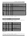
1
Torus User Manual 02 Aug 2013 Contributors: Alicia Aarnio, David Acreman, Tim Harries, Thomas Haworth, David Rundle. TWiki to PDF Converter TWiki2pdf Version 2.3.4 by Steve Lloyd. Copyright c 2004-2013 by the contributing authors. Contents Preface iii 1 Introduction 1 2 Building Torus 3 2.0.1 Getting the Torus code . . . . . . . . . . . . . . . . . . . . . . . . . . . . . . . . . . . . . . 3 2.0.2 Compilers . . . . . . . . . . . . . . . . . . . . . . . . . . . . . . . . . . . . . . . . . . . . . 3 2.0.3 Building Torus . . . . . . . . . . . . . . . . . . . . . . . . . . . . . . . . . . . . . . . . . . . 3 2.0.4 Testing your build . . . . . . . . . . . . . . . . . . . . . . . . . . . . . . . . . . . . . . . . . 4 3 Running Torus 6 3.0.5 Running torus . . . . . . . . . . . . . . . . . . . . . . . . . . . . . . . . . . . . . . . . . . . 6 3.0.6 Creating a parameters file . . . . . . . . . . . . . . . . . . . . . . . . . . . . . . . . . . . . . 6 3.0.7 Top level keywords . . . . . . . . . . . . . . . . . . . . . . . . . . . . . . . . . . . . . . . . 8 3.0.8 Setting up the AMR grid . . . . . . . . . . . . . . . . . . . . . . . . . . . . . . . . . . . . . 9 3.0.9 Geometry . . . . . . . . . . . . . . . . . . . . . . . . . . . . . . . . . . . . . . . . . . . . . 9 3.0.10 Physics . . . . . . . . . . . . . . . . . . . . . . . . . . . . . . . . . . . . . . . . . . . . . . . 10 3.0.11 Type of calculation . . . . . . . . . . . . . . . . . . . . . . . . . . . . . . . . . . . . . . . . 10 3.0.12 Checking your parameters file . . . . . . . . . . . . . . . . . . . . . . . . . . . . . . . . . . . 10 4 Plotting Torus Data 12 4.0.13 Plotting images . . . . . . . . . . . . . . . . . . . . . . . . . . . . . . . . . . . . . . . . . . 12 4.0.14 Plotting spectral energy distributions . . . . . . . . . . . . . . . . . . . . . . . . . . . . . . . 13 ii CONTENTS CONTENTS 5 The physics modules 14 5.0.15 Introduction . . . . . . . . . . . . . . . . . . . . . . . . . . . . . . . . . . . . . . . . . . . . 14 5.0.16 Describing the size and chemistry of the dust . . . . . . . . . . . . . . . . . . . . . . . . . . 14 5.0.17 Setting up the initial conditions for the Lucy iterations . . . . . . . . . . . . . . . . . . . . . 15 5.0.18 On convergence . . . . . . . . . . . . . . . . . . . . . . . . . . . . . . . . . . . . . . . . . . 15 5.0.19 Common pitfalls . . . . . . . . . . . . . . . . . . . . . . . . . . . . . . . . . . . . . . . . . . 15 5.0.20 Calculating SEDs . . . . . . . . . . . . . . . . . . . . . . . . . . . . . . . . . . . . . . . . . 16 5.0.21 Calculating images . . . . . . . . . . . . . . . . . . . . . . . . . . . . . . . . . . . . . . . . 17 5.0.22 Output files . . . . . . . . . . . . . . . . . . . . . . . . . . . . . . . . . . . . . . . . . . . . 18 5.0.23 Molecular Line Transfer Calculations . . . . . . . . . . . . . . . . . . . . . . . . . . . . . . . 18 5.0.24 Atomic Line Transfer Calculations . . . . . . . . . . . . . . . . . . . . . . . . . . . . . . . . 19 5.1 Photoionization Models . . . . . . . . . . . . . . . . . . . . . . . . . . . . . . . . . . . . . . . . . . 20 5.1.1 Domain Decomposed Photoionization Models . . . . . . . . . . . . . . . . . . . . . . . . . . 20 5.1.2 The Stack Limit . . . . . . . . . . . . . . . . . . . . . . . . . . . . . . . . . . . . . . . . . . 20 5.1.3 Monochromatic Models (domain decomposed models only) . . . . . . . . . . . . . . . . . . . 21 5.1.4 On The Spot Approximation . . . . . . . . . . . . . . . . . . . . . . . . . . . . . . . . . . . 22 5.1.5 Simplified Thermal Calculation . . . . . . . . . . . . . . . . . . . . . . . . . . . . . . . . . . 22 5.1.6 Variance Reduction . . . . . . . . . . . . . . . . . . . . . . . . . . . . . . . . . . . . . . . . 22 5.1.7 Periodic Boundary Conditions(domain decomposed models only) . . . . . . . . . . . . . . . . 23 5.1.8 Customizing Atomic Species . . . . . . . . . . . . . . . . . . . . . . . . . . . . . . . . . . . 23 5.1.9 Retrieving data from .grid files . . . . . . . . . . . . . . . . . . . . . . . . . . . . . . . . . . 23 5.2 Creating Synthetic Images . . . . . . . . . . . . . . . . . . . . . . . . . . . . . . . . . . . . . . . . . 24 5.3 Hydrodynamics . . . . . . . . . . . . . . . . . . . . . . . . . . . . . . . . . . . . . . . . . . . . . . 24 5.4 5.3.1 Flux limiting . . . . . . . . . . . . . . . . . . . . . . . . . . . . . . . . . . . . . . . . . . . . 24 5.3.2 Rhie Chow Interpolation . . . . . . . . . . . . . . . . . . . . . . . . . . . . . . . . . . . . . 25 5.3.3 Boundary Conditions . . . . . . . . . . . . . . . . . . . . . . . . . . . . . . . . . . . . . . . 25 5.3.4 Artificial Viscosity . . . . . . . . . . . . . . . . . . . . . . . . . . . . . . . . . . . . . . . . . 26 5.3.5 Saving time and space in large calculations . . . . . . . . . . . . . . . . . . . . . . . . . . . 26 Radiation Hydrodynamics . . . . . . . . . . . . . . . . . . . . . . . . . . . . . . . . . . . . . . . . . 27 iii CONTENTS CONTENTS 6 Defining radiation sources 6.0.1 28 Defining radiation sources . . . . . . . . . . . . . . . . . . . . . . . . . . . . . . . . . . . . . 28 7 Adaptive Mesh Refinement 30 8 Geometries 31 8.0.2 Protoplanetary disc geometry . . . . . . . . . . . . . . . . . . . . . . . . . . . . . . . . . . . 31 8.0.3 ttauri geometry . . . . . . . . . . . . . . . . . . . . . . . . . . . . . . . . . . . . . . . . . . 31 8.0.4 Magnetosphere parameters . . . . . . . . . . . . . . . . . . . . . . . . . . . . . . . . . . . . 32 8.0.5 Disc wind parameters . . . . . . . . . . . . . . . . . . . . . . . . . . . . . . . . . . . . . . . 32 8.0.6 Dusty disc parameters . . . . . . . . . . . . . . . . . . . . . . . . . . . . . . . . . . . . . . . 32 9 Using Torus with SPH data 34 9.1 Generating Torus grids from SPH data . . . . . . . . . . . . . . . . . . . . . . . . . . . . . . . . . . 34 9.2 SPH-Torus . . . . . . . . . . . . . . . . . . . . . . . . . . . . . . . . . . . . . . . . . . . . . . . . . 35 10 Torus input parameters 36 10.1 Unit Directory . . . . . . . . . . . . . . . . . . . . . . . . . . . . . . . . . . . . . . . . . . . . . . . 39 10.1.1 Available units . . . . . . . . . . . . . . . . . . . . . . . . . . . . . . . . . . . . . . . . . . . 39 10.1.2 Unit Types (for developers) . . . . . . . . . . . . . . . . . . . . . . . . . . . . . . . . . . . . 41 11 Torus Publications 42 iv Preface Exeter is home to the 3-dimensional radiative-transfer code, TORUS, which is either an acronym for Transport of Radiation Under Sobolev, or Transport of Radiation Using Stokes. v Chapter 1 Introduction TORUS is a radiation transfer and radiation-hydrodynamics code developed by Tim Harries and co-workers. Originally developed at St. Andrews and UCL the code developers are now primarily based at the University of Exeter in the sunny southwest of the UK near the English Riviera1 . The basic philosophy of TORUS is one of flexibility. The code has a basic infrastructure that includes the AMR mesh scheme (first developed by Neil Symington) that is used by several physics modules including atomic line transfer in a moving medium (developed by Tim Harries, Ryuichi Kurosawa and Neil Symington), molecular line transfer (Dave Rundle and Tim Harries), photoionization (Tim Harries), radiation hydrodynamics (Tim Harries, Dave Acreman, Tom Haworth) and radiative equilibrium (Tim Harries, Dave Acreman, Ryuichi Kurosawa). The code has been used to tackle a wide variety of problems from magnetospheric accretion onto T Tauri stars, spiral nebulae around WolfRayet stars, discs around Herbig AeBe stars, structured winds of O supergiants and Raman-scattered line formation in symbiotic binaries, and dust emission and molecular line formation in star forming clusters. As of today (6th January 2011) the code consists of approximately 145000 lines of Fortran 2003. The code itself is written to fairly tight coding guidelines, and should be fairly readable - although it is admittedly sparsely commented we use self-explanatory variable and subroutine names as much as possible. The code also makes extensive use of fortran modules, and is compiled using a standard Gnu makefile. The code is parallelized using both MPI and OMP, and can uses these parallel sections either separately or in a hybrid mode. Most physics modules have quite low communication overhead. TORUS has been compiled on a wide variety of system architectures. We regularly run the code at Exeter using ifort and compile the code nightly using g95, ifort, gfortran and nagfor. A nightly test suite (developed by Dave A) is run from the CVS repository ensuring that the current CVS version at least compiles and runs basic benchmarks for radiative equilibrium, molecular statistical equilibrium and hydrodynamics (a Sod shock tube test). We rely very little on external libraries. If you want to have your output files as FITS (which we recommend) then you need to have the cfitsio library installed and in your linking path when compiling. You need MPI libraries (we use the intel one or openMPI here) if you want to use the MPI parallelization, and you need an OMP-directive compatible fortran compiler to access the OMP or hybrid modes. Visualization of the torus models can be achieved via any suitable 3rd party program that can read the VTK format files that TORUS produces (we prefer visit here, but paraview can be good too). If you are reading this then you have been given access to TORUS - please respect our intellectual property and do not distribute the code. We are of course really happy for groups to use the code and are excited to see results from it appearing in the refereed literature. Finally the TORUS code is the result of the intellectual effort of a small group of dedicated astronomers, most of whom are at a fairly early career stage. It is therefore extremely important that they get credit for their hard work!! Tim Harries 6th January 2011 1 CHAPTER 1. INTRODUCTION 1 May I ask what you expected to see out of a Torquay hotel bedroom window? Sydney Opera House, perhaps? The Hanging Gardens of Babylon? Herds of wildebeest sweeping majestically...? Basil Fawlty Complete: Responsible: Author: David Acreman 13 Feb 2009 Contributors: David Acreman Last significantly modified by: David Acreman 13 Feb 2009 Not yet reviewed 2 Chapter 2 Building Torus 2.0.1 Getting the Torus code The Torus code is managed using SVN. To download the code from the repository type: where USERNAME is your username on mail.astro.ex.ac.uk. 2.0.2 Compilers Torus is known to build using the freely available gfortran compiler and the commercial Intel Fortran compiler. These compilers are routinely used to run Torus so you can expect them to run typical configurations successfully. The NAG Fortran compiler is also used to build Torus, so it should work but is not so frequently tested. g95 has been removed from the Torus test suite as the compiler is no longer being developed and building with gfortran gives better performance. 2.0.3 Building Torus The Torus repository contains a Makefile which can be used to build the code for a number of different systems. System specific options (e.g. compiler flags) are specified in the Makefile so you should not need to set these up, unless you are using a new system. The environment variable SYSTEM is used to tell the Makefile which configuration to use. For example to use the gfortran configuration (suitable for the gfortran compiler on Mac OS X and Linux .e.g. in csh type setenv SYSTEM gfortran Alternatively you can set this environment variable in your .cshrc file. The this table describes the supported SYSTEM types relating to specific compilers: SYSTEM gfortran ifort g95 nagfor The The The The Description GNU gfortran compiler (gcc.gnu.org/fortran) intel compiler g95 compiler (www.g95.org) Nagware fortran compiler Can use mpi=yes option? Yes (can also use ompiosx system) Yes No, use ompi system No The this table describes the currently supported SYSTEM types relating to specific machines: 3 CHAPTER 2. BUILDING TORUS SYSTEM complexity zen zensingle zenmpt Description The Leicester Dirac system AKA complexity cluster intel MPI compiler on the SGI-Altix system at Exeter single processor compilation on SGI-Altix system Use SGI’s MPI Toolkit on zen You can now go into the torus directory and build the code cd t o r u s make d e p e n d s make Several options can be passed to the make process: Option cfitsio debug profile static trace openmp coverage hydro photoion molecular sph atomic hdf Description Link with cfitsio libraries Switch on debugging flags Enable profiling Perform static linking Use Intel trace collector Build with OpenMP parallelism Enable coverage analysis with gcov Include hydrodynamics Include photoionisation Include molecular physics Include code for making grids from SPH Include atomic physics Build with hdf5 support required for reading flash dumps Default yes no no no no no no yes yes yes yes yes no Notes Not available on Mac OS X Intel compilers only gnu compilers only For example to build torus without linking to the cfitsio libraries and with debug flags enabled use make c f i t s i o =no debug=y e s Building without the photoion or sph options will result in a slightly smaller memory footprint for the grid (there are statically allocated octal components which are excluded). You may need to remove all files from a previous build and start from scratch (for example if you have previously compiled with debug flags and need to recompile without debug flags). The Makefile has an option to clean up files from the previous build make clean Building Torus on Mac OS X To link with the FITS library under OS X make sure that libcfitsio.a is in the default search path (e.g. /usr/local/lib or /usr/lib). 2.0.4 Testing your build Assuming that you complete compilation without error messages, you can check that your torus executable is doing the right thing using the benchmark tests that torus runs on an nightly basis. The parameter files and scripts to check the test results are located at / t o r u s / benchmarks / 4 CHAPTER 2. BUILDING TORUS The tests themselves cover different aspects of the code including hydrodynamics (/torus/benchmarks/hydro1d), photoionization(HII region, HII regionMPI) and molecular line transport (molebench). Copy your torus executable into a benchmark folder, run the code and check the results. Complete: Responsible: Author: David Acreman 13 Feb 2009 Contributors: David Acreman Last significantly modified by: David Acreman 13 Feb 2009 Not yet reviewed 5 Chapter 3 Running Torus 3.0.5 Running torus The torus distribution contains a variety of data files such as model atmospheres, grain refractive indices and stellar evolution tracks. These are stored in the ”data” subdirectory of the torus distribution. In order for the code to access these the environment variables TORUS DATA must be set e.g. in csh setenv TORUS DATA /mypathtotorus/torus/data Once you have compiled the code you will have an executable called torus.xxx where xxx is defined by your SYSTEM type (e.g. torus.gfortran). In order to run the code you need to execute the torus executable in a directory that contains a parameters (input) file. For example if you have a directoy /home/myusername/model then cd into that directory and run torus: $ /my-path-to-torus/torus.xxx Torus will then run, and will look for a file called parameters.dat. If you have called your parameters file something different (e.g. mymodel.dat) then $ /my-path-to-torus/torus.xxx mymodel.dat will run torus on mymodel.dat Complete: Responsible: Author: Tim Harries 24 Aug 2010 Contributors: Tim Harries Last significantly modified by: Tim Harries 24 Aug 2010 Not yet reviewed 3.0.6 Creating a parameters file The parameters file basically consists of a list of keywords and associated values. The keywords are case sensitive, and should appear as the first non-whitespace characters on a given line of the input file. The next non-whitespace characters should be the value associated with that keyword. Characters after the keyword/value pair are ignored, and lines that start with a # or ! keyword are also ignored. Keywords may appear in any order in the input file (although for clarity you will wish to collect keywords referring to particular part of the model together). This gives significant flexibility in formatting the TORUS parameter file for maximum clarity. Note that each unique keyword should appear only once in the parameters file. As an example say we have a keyword nphotons which we wish to assign a value of 1000. We could write this as 6 CHAPTER 3. RUNNING TORUS nphotons 1000 as one line in the parameters file. But this doesn’t contain any comments to remind the user what this is for, so it may be better to write nphotons 1000 ! The number of photons used to produce the SED The above is more user-friendly. We can also put comments on their own lines, but make sure they start with a # or a ! e.g. ! The f o l l o w i n g p a r a m e t e r s d e s c r i b e t h e image n p h o t o n s 1000 ! The number o f p h o t o n s u s e d t o p r o d u c e t h e SED i m a g e s i z e 100 ! The l i n e a r image s i z e i n AU n p i x e l s 100 ! Pr od uc e a 100 x100 p i x e l image noscat T ! c a l c u l a t e image w i t h o u t s c a t t e r e d l i g h t The values associated with keywords may be integer, logical (T or F), or floating point. Normally only one value is associated with each keyword, although a limited number require an array of values (separated by whitespace) e.g. sourceposition1 0. 12. 7. ! first source position in units of 1010 cm Only a subset of keywords must be specified at run-time. Others will take on a default value which is normally sensible. If a keyword is not in the parameters file but it is required for the model the code will exit and tell you that a particular keyword/value pair must be specified. TORUS will stop with a fatal error if a particular keyword appears more than once in an parameters file. It will also report keywords that were unused on input. To check your parameters file run TORUS with the word ”check” afterwards. This causes TORUS to read your parameters file then exit, so that you can test for errors without actually running the model. Here is an example TORUS input parameter file for the Pascucci circumstellar disc benchmark. ! Torus v2 p a r a m e t e r f i l e f o r 2D benchmark d i s c ! See P a s c u c c i e t a l , 2 0 0 4 , A&A , 4 1 7 , 793 dustphysics T radeq T ! use dust m i c r o p h y s i c s ! perform a r a d i a t i v e e q u i l i b r i u m c a l c u l a t i o n ! AMR g r i d p a r a m e t e r s readgrid F ! we a r e n ’ t r e a d i n g a g r i d , we w i l l s e t one up from s c r a t c h w r i t e g r i d F ! we don ’ t need t o w r i t e o u t t h e AMR f i l e − we j u s t need SEDs a m r g r i d s i z e 4 . e6 ! t h e l i n e a r s i z e o f t h e top− l e v e l AMR mesh i n u n i t s o f 10ˆ10 cm amr2d T ! t h i s i s a 2d ( c y l i n d i c a l ) model ! g r i d smoothing s w i t c h e s smoothgridtau T photosphere dosmoothgrid T ! smooths t h e g r i d f o r o p t i c a l depth , i n o r d e r t o r e s o l v e d i s c ! smooth t h e g r i d f o r jumps i n c e l l r e f i n e m e n t 7 CHAPTER 3. RUNNING TORUS s m o o t h f a c t o r 3 . 0 ! make s u r e t h a t n e i g h b o u r i n g c e l l s a r e n o t o n l y one AMR d e p t h apart ! Source parameters n s o u r c e 1 ! t h e r e i s j u s t one s o u r c e r a d i u s 1 1 . ! i t has a r a d i u s of 1 s o l a r r a d i u s t e f f 1 5800. ! the source e f f e c t i v e temperature c o n t f l u x 1 b l a c k b o d y ! t h e c on tin uum f l u x i s assumed t o be a b l a c k b o d y mass1 1 . ! t h e s o u r c e h a s a mass o f one s o l a r mass sourcepos1 0. 0. 0 ! i t i s located at the g r i d centre ! Geometry s p e c i f i c p a r a m e t e r s g e o m e t r y benchmark ! t h i s i s t h e P a s c u c c i ( 2 0 0 4 ) benchmark r i n n e r 1 . ! i n n e r d i s c r a d i u s (AU) r o u t e r 1000. ! outer d i s c r a d i u s h e i g h t 1 2 5 . ! d i s c s c a l e h e i g h t a t 100 AU ( i n AU) r h o 8 . 1 6 1 3 6 e −18 ! d e n s i t y a t i n n e r e dge m i d p l a n e ( g / c c ) ! Dust g r a i n p r o p e r t i e s iso scatter T graintype1 s i l d l amin1 0 . 1 2 amax1 0 . 1 2 0 1 qdist1 0.01 ! ! ! ! ! Assume i s o t r o p i c s c a t t e r i n g ( assumed by benchmark ) D r a i n and Lee s i l i c a t e s minimum g r a i n s i z e ( m i c r o n s ) maximum g r a i n s i z e ( m i c r o n s ) power law i n d e x ( f l a t ) ! Output SEDs spectrum T ! produce a spectrum ! SED p a r a m e t e r s ninc 2 f i r s t i n c 12.5 l a s t i n c 77.5 n p h o t o n s 500000 filename test sised T d i s t a n c e 2 . 2 5 5 5 8 e−8 sedlamm in 0 . 1 2 sedlammax 2000 sedwavlin F 3.0.7 ! ! ! ! ! ! ! ! ! ! number o f i n c l i n a t i o n s the f i r s t i n c l i n a t i o n ( degrees ) the l a s t i n c l i n a t i o n ( degrees ) t h e number o f photon p a c k e t s i n e a c h SED the root of the output filename W r i t e s p e c t r u m a s lambda v s F lambda i n S I u n i t s Distance to o b s e r v e r minimum w a v e l e n g t h i n SED f i l e maximum w a v e l e n g t h i n SED f i l e L i n e a r s p a c i n g i n SED f i l e ? Top level keywords The basic architecture of the parameters file follows three stages. The first is to setup up the AMR mesh, the second is to perform some physics (radiative equilibrium, hydrodynamics etc) and the third is to produce some outputs (dust continuum images, molecular line datacubes, Halpha spectra etc). Here we describe the most important keywords for setting up the model. Naturally each choice of grid setup, physics, and outputs, leads to a further set of parameter keywords that must be specified, which are detailed in the chapters that deal with the individual physical models that can be computed. 8 CHAPTER 3. RUNNING TORUS 3.0.8 Setting up the AMR grid There is a choice of AMR dimensionality and coordinate system. This is done by setting one (and only one) of amr1d or amr2d or amr3d to T. The standard 3-d cartesian grid is specified by amr3d T ! g r i d i s t h r e e d i m e n s i o n a l and gives a grid of 2x2x2 cubes each of which can be further sub-divided, leading to an AMR structure stored as an octree. Should your problem contain a high degree of rotational symmetry then you may wish to employ the 3-d cylindrical grid, specified as follows: amr3d T ! g r i d i s t h r e e d i m e n s i o n a l c y l i n d r i c a l T ! use c y l i n d r i c a l c o o r d i n a t e s In the cylindrical system x is radius, z is height and the third dimension (phi) is azimuthal angle. Each cell in the grid can have either four children (the cell is split in x and z but not phi) or eight children (cell is split in x, z, and azimuthal extent). Should your model be axisymmetric (such as a disc) the grid should be specified as 2d, using amr2d T ! g r i d i s 2−d c y l i n d r i c a l which gives a quad-tree grid where x is the radius and z is height. (Note that in the hydrodynamical case only the 2d geometry is a cartesian surface). One dimensional grids are specified by amr1d T ! g r i d i s one d i m e n s i o n a l This provides an AMR bi-tree, where the x-coordinate becomes radius. This is suitable for spherically symmetric models (the molecular benchmark is an example of this type of mesh. (Note that in the hydrodynamics case only the amr1d mode has x as a linear coordinate, not a radius.) The size of the AMR mesh is give by amrgridsize which refers to the full extent of the root cell. The distance is given in units of 1010 cm, which are the general code units for distance. The centre of the AMR mesh is assumed to be at (0, 0, 0) for the three-d cases and (r=amrgridsize/2, z=0) for the 2-d cylindrical mode. The cell depth in TORUS is measured from 1 for the root cell to N where amrgridsize/(2N ) is the dimension of the smallest cell in the AMR mesh . The grid is always split to a depth specified by mindepthamr (default 5) and the maximum depth is set using maxdepthamr (which defaults to 31). Note that the memory footprint of the AMR mesh is strongly dependent on these two parameters, and these should be adjusted with caution (and maxdepthamr should certainly not be revised upwards, only downwards). 3.0.9 Geometry The geometry keyword specifies the type of model you wish to run, be it a protostellar disc, a stellar wind, a Bonnor-Ebert sphere, etc etc. The following non-exhaustive list provides the most commonly used geometries in TORUS: 9 CHAPTER 3. RUNNING TORUS Geometry molbench benchmark shakara ttauri cmfgen cluster theGalaxy molcluster wr104 clumpyagb starburst runaway protobin Description The molecular benchmark test of xxxx The Pascucci (2004) disc benchmark An alpha-disc magnetospheric accretion model Uses input opacities from Hillier’s cmfgen code Uses a cluster from Bate’s SPH models as input Uses Dobb’s SPH galaxy simulation as input Uses one of Bate’s SPH simulations as input Spiral WR nebula model A clumpy AGB wind A starburst simulation Uses VH1 hydro simulation as input Protostellar binary formation model (a la Bate et al. 1995) Specifying a geometry usually defines a set of other keywords (such as the disc scaleheight, the microturbulence etc etc) than must also be assigned values. Specific cases are dealt with later in the manual. 3.0.10 Physics There are several different microphysical processes that may be considered. Some of these can be considered simultaneously (e.g. dust and photoionization, or dust and molecules). Some processes are mutually exclusive (for example molecular physics and atomic physics). Setting any of these keywords to true will then mean that a further subset of keywords must be specified, which are detailed later. Physics dustphysics molecularphysics atomicphysics photoionphysics 3.0.11 Description This will include dust emission/absorption processes This will include molecular opacities Atomic physics (currently limited to H/He) Photoionization physics (H/He/C/N/O/S/Si/Ne etc) Type of calculation Once the geometry has been specified, and the different microphysical processes that need to be considered have been detailed, the user must select the type of calculation they wish to perform: • Statistical equilibrium stateq T . Conduct a statistical equilibrium calculation by solving the rate equations. If you have molecularphysics T then an algorithm described in Rundle et al. (2010) is used. If atomicphysics T then a comoving frame algorithm is employed. • Radiative equilibrium radeq T. This requires that dustphysics T and uses the Monte-Carlo radiative equilibrium method of Lucy (1999). • Photoionization equilibrium photoion eq. Solves photoionization equilibrium including thermal equilibrium using a method similar to that of Ercolano xxxx. Dust may be included. • Hydrodynamics hydrodynamics T. This solves hydrodynamics using a TVD scheme and superbee flux-limiter. 3.0.12 Checking your parameters file Once you have written a parameters file you can get Torus to check it for you. Run the Torus executable with the word check afterwards, optionally followed by the name of your parameters file (if it is not called parameters.dat). For example you can use the command torus.openmp check mypar.dat to check a parameters file called mypar.dat using a torus executable called torus.openmp. 10 CHAPTER 3. RUNNING TORUS Complete: Responsible: Author: Tim Harries 07 May 2010 Contributors: Tim Harries Last significantly modified by: Tim Harries 07 May 2010 Not yet reviewed 11 Chapter 4 Plotting Torus Data TORUS used to produce graphical output using internal PGPLOT calls, but these calls have now been removed in order to increase TORUS portability. 4.0.13 Plotting images VTK files Output of grid data for plotting may now be made using calls to vtk mod subroutines, which produce VTK format files. VTK files produced by Torus on the fly include: filename lucy.vtk bias.vtk beforesmooth.vtk aftersmooth.vtk rho.vtk Description Overwritten with each Lucy iteration, contains crossings, deltat, dust1, etacont, etaline, fixedtemp, mesh quality Contains: chiline, mesh quality, and temperature. Contains: inflow, mesh quality, rho, temperature, and velocity magnitude. Contains: inflow, mesh quality, rho, temperature, velocity magnitude. VTK files can be plotted with the VisItVisualization Tool. You may also like to try paraview. FITS images See the Dust Continuum Models section (subsection ”Calculating Images”) for more information on how to produce image files. The SAO DS9 GUI can be used to plot FITS files. To view spectral line profiles, the program kvis handles data cubes (output as described in the atomic line transfer calculations section) effectively. The following is an example of the fits output of an atomic line transfer model run: • KvisScreenShot1: Clicking View will open this window: • KvisScreenShot2: Once Profile Mode is changed from ”none” to any other option, a profile viewing window will pop up (see next image for example). To view spectral lines wherever your cursor is, choose ”line” as the profile mode, and be sure the ”track cursor” box is checked. As you move the mouse around the main display window, the line profile will auto-update in the profile window. 12 CHAPTER 4. PLOTTING TORUS DATA • KvisScreenShot3: Auto V Zoom scales the intensity axis on the fly depending on where your cursor is; uncheck this (and click Unzoom) to fix the y axis display to the full range. To adjust the display settings in the profile window, click Overlay and select ”axis labels.” This box will pop up: • KvisScreenShot4: Once ”enable” is checked, select display settings as desired. Additional notes • To generate a box average of the spectral line in a given region, change Profile Mode to ”box average,” and middle click-drag (alt+click-drag on macs) to define a rectangular region on the image. After a moment, the averaged line profile within your defined region will appear in the profile window. • kvis can also generate movies- click Movie in the view control window. The default setting is for the X-Y plane to be the ”slice direction,” with the movie progressing through z values in the data cube (in our case, velocities). • The scroll wheel on the mouse can be used to zoom in/out in the main display window, and control+left click-drag can be used to define a rectangular zoom area in the image. 4.0.14 Plotting spectral energy distributions The creation of .dat files containing spectra is described here (subsection Calculating SEDs). SEDs can be plotted using IDL with relative ease (will attach sample code here soon). Complete: Responsible: Author: Alicia Aarnio 26 Aug 2010 Contributors: Alicia Aarnio Last significantly modified by: Alicia Aarnio 26 Aug 2010 Not yet reviewed 13 Chapter 5 The physics modules 5.0.15 Introduction Torus uses the radiative-equilibrium method of Lucy (1999) to calculate dust temperatures for arbitrary distributions of dust illuminated by multiple radiation sources. New users should read and become familiar with the photon-packet algorithm described in Lucy’s paper. The following chapter details the input keywords required to compute a radiative-equilibrium model and to calculate emergent SEDs and images. Some pitfalls and gotchas are also described which should help the novice user. 5.0.16 Describing the size and chemistry of the dust The dust grain size distribution and chemistry must be specified using keywords if dustphysics T is set. An arbitrary number of different grain sizes and chemistries can be listed by the keyword ndustype, which requires an integer value. The minimum grain size (in microns) is set using amin, the maximum using amax the power-law index as qdist. graintype1 d r a i n e g r a i n f r a c 1 0.01 amin1 0 . 1 amax1 1 . 0 ! qdist1 3.5 s i l ! Draine (2003) s i l i c a t e s ! 1 : 1 0 0 d u s t : t o : g a s mass r a t i o ! minimum g r a i n s i z e ( m i c r o n s ) maximum g r a i n s i z e ( m i c r o n s ) ! power law i n d e x ( a ˆ −3.5) The following table gives details of the different grain chemistries currently coded: graintype draine sil Description Draine (2003) silicate grains Alternatively you can provide your own grain optical constants in a text file. This file must have three space-delimited columns (Wavelength (microns), Real part of n, imaginary part of n). Comments starting in the first column with a hash symbol are ignored. You must also specify the density of the grain material in grams per cc. g r a i n t y p e 1 mygrains . dat g r a i n d e n s i t y 1 3 . 5 ! d e n s i t y o f g r a i n m a t e r i a l i n grams / c c g r a i n f r a c 1 0.01 ! 1 : 1 0 0 d u s t : t o : g a s mass r a t i o amin1 0 . 1 ! minimum g r a i n s i z e ( m i c r o n s ) amax1 1 . 0 ! maximum g r a i n s i z e ( m i c r o n s ) qdist1 3.5 ! power law i n d e x ( a ˆ −3.5) 14 CHAPTER 5. THE PHYSICS MODULES 5.0.17 Setting up the initial conditions for the Lucy iterations There are several keywords associated with the numerics of the Lucy algorithm that can be tweaked, but for which the default values will usually give satisfactory results. The number of photon packets is by default set to be 10 times the number of grid cells (in order to provide adequate sampling of the radiation field in each cell), but this can be adjusted using the nlucy keyword. Solving radiative equilibrium satisfactorily requires adequate spatial resolution, and this is particularly important for the transition between optically thin and optically thick regions (such as the surface of a disc or the inner radius of a dust shell). If smoothgridtau is set to true in the input file an iterative sweep is performed over the grid comparing the optical depth across a given cell (at a given wavelength) with those of its neighbours. If one of the cells has an optical depth of greater than taumax and its neighbour has an optical depth of less than taumin then the more optically thick cell is split. The sweep is performed at wavelengths between lambdasmooth and the maximum wavelength under consideration (normally 2 millimetres). The dosmoothgrid parameter may also be set. This invokes a smooth that ensures that the size ratio of neighbouring cells does not exceed smoothfactor (by default 3). Large differences in cell AMR depths for adjacent cells can lead to numerical problems, so it is a good idea to have dosmoothgrid T in your input file. 5.0.18 On convergence Lucy’s method is an iterative one, that will gradually converge towards radiative equilibrium. Since the method is a Monte-Carlo one the temperatures of cells will have noise associated with them, so convergence must be defined in a statistical sense. It should be remembered that the more photon packets that are run, the better the temperature estimate will be, and the more likely it is that cells with propagate into optically thick regions. However for some models, such as a canonical T Tauri star disc, the optical depths to the midplane are such that the chance of an individual photon packet penetrating to the midplane are vanishingly small, and even very large numbers of photon packets will leave such cells ’undersampled’. Undersampled in this context means that the number of photons passing through a given cell is smaller than mincrossings, so the algorithm cannot be used to adequately estimate the mean intensity for that cell. At the end of a particular iteration there may be some volumes within the grid that contain many such undersampled cells. Torus employs the diffusion approximation in these regions, using the surround cells that do have well-sampled radiation fields as a boundary condition. The use of the diffusion approximation is controlled by a number of keywords that are initialised using sensible defaults: Cells with a Rosseland optical depth taudiff are always part of the diffusion calculation. Cells that are diffdepth from the effective surface of the structure (e.g. the disc) are always in the diffusion zone. The iterative scheme proceeds as follows. The photon packets are run through the grid, and the new temperatures are calculated (either from the MC estimators or the diffusion approximation). The number of undersampled cells is found (these are cells that have been sampled by fewer than mincrossings photon packets and yet have a Rosseland optical depth of less than taudiff). If the percentage of undersampled cells is greater than lucy undersampled then the number of photon packets is doubled for the next iteration. The convergence criterion considers the emissivity of the dust. If the percentage change of the emissivity is less than one percent compared to the previous iteration then the Lucy algorithm finishes. The file lucy convergence.dat provides detailed information on an iteration-by-iteration basis of the convergence of the radiative equilibrium. 5.0.19 Common pitfalls Here we list some common problems: 15 CHAPTER 5. THE PHYSICS MODULES • If mincrossings is set too small then the MC estimator for the radiation-field, and therefore the temperature etc for some cells can be very noisy, and although the percentage of undersampled cells is small the error on the dust emissivity will be large and the convergence criterion will never be triggered. • Dust sublimation. If your inner disc radius is too small then the dust temperature at the inner disc can exceed the dust sublimation temperature. In order to ensure you have a consistent inner disc temperature you should set vardustsub T in your model, while will invoke the routines to systematically produce the correct inner disc shape. 5.0.20 Calculating SEDs Once the radiative-equilibrium is complete one can produce spectra across an arbitrary wavelength region at an arbitrary resolution (although fundamentally the resolution of the spectrum is limited by the resolution at which the grain refractive indices were originally computed). The SEDs can be output for a variety of units. To produce a spectrum set spectrum T in the input file, along with filename, which is the name for your SED file. Setting sed T will produce a lambda vs lambda * F lambda file. The wavelength range of the SED will run from sedlammin to sedlammax with sednumlam points. Note that the wavelength spacing is normally logarithmic (sedwavlin T will produce linearly spaced wavelength points. The SED production is Monte-Carlo in nature (this allows for anistropic scattering and polarization to be computed), so one can specify the number of photon packets used nphotons (this number of packets is divided up evenly amongst the number of wavelength bins, so the higher your resolution the more packets you need for the same signal-to-noise). The observer distance is set using distance xx where xx is the distance from the grid origin to the observer in units of parsecs. For non-spherical geometries the SED will be inclination dependent and torus can produce a series of SEDs for different inclinations. The number of inclinations is specified using ninc and the individual inclinations can then be specified as an array ninc 4 ! t h e number o f i n c l i n a t i o n i n c l i n a t i o n s 0. 30. 60. 90. ! the d i f f e r e n t i n c l i n a t i o n s in degrees or as a range of values separated in uniform steps of cosine inclination ninc 4 ! t h e number o f i n c l i n a t i o n i n c l i n a t i o n s 0 . . 90. ! the range of i n c l i n a t i o n s in degrees Alternatively you can specify the first and last inclinations (again separated in uniform steps of cosine inclination) n i n c 4 ! t h e number o f i n c l i n a t i o n s f i r s t i n c 0. ! the f i r s t i n c l i n a t i o n l a s t i n c 90. ! the l a s t i n c l i n a t i o n If you want even spacing in inclination angle, rather than cos inclination, set sedcosspaced F in the parameters file. The output filenames are then inclination dependent, with incxx appended to filename where xx is the inclination of that model in degrees. Ancillary files are also output: stellar direct is the spectrum produced 16 CHAPTER 5. THE PHYSICS MODULES photons that arrive at the observer directly from the stellar photons. The stellar scattered spectrum arises solely from stellar photons that are scattered one or more times towards the observer. thermal direct is the spectrum of photons that are emitted by the disc and arrive without scattering at the observer. thermal scattered are photons produced by dust that have been scattered one or more times before arriving at the photosphere. For 3D geometries the SED will depend on a second angle (in addition to the inclination). A position angle can be set using the firstPA and lastPA parameters which results in evenly sampled angles between firstPA and lastPA over ninc steps. To scan through position angles, whilst keeping the inclination constant, just set firstinc equal to lastinc. Non-zero position angles will result in PAxx being appended to filename where xx is the position angle of that model in degrees. Alternatively you can use the posangs parameter to specify a list of angles or a range, in the same way that the inclinations parameter is used. If you are specifying both inclinations and position angles then this should be done using the same method (e.g. if you use the inclinations parameter then the position angles should be specified using posangs). 5.0.21 Calculating images Images are calculated using the same code that produces the SEDs. First one must set image T in the input file. Torus can produce a sequence of images. In order to do this set nimage xx where xx is the number of images and append each keyword with the appropriate image number. The observer distance is set using distance xx where xx is the distance between the observer and the grid origin in parsecs. The name of the image file is set via the imagefile keyword and the wavelength of the monochromatic image is set by lambdaimage where the units of wavelength is angstroms. The nphotons keyword allows one to control the signal-to-noise of the image. The axis units of the fits images are set using imageaxisunits xx, where xx can be au, pc, cm or arcsec, (the default is au). imagesize sets the size of one side of the (square) image in the same units as the image axes (the default size is the maximum linear size of the grid). npixels defines the number of pixels along one side of the image (i.e. the image has npixels-squared pixels in total). The size of the images is controlled by imagesize but can be overridden for one or more images, for example imagesize3 changes the size of the third image. By default images are square but this can be changed using the imageaspect keyword. The y-axis is of size imagesize with npixels pixels, but the x-axis size and number of pixels will be scaled by imageaspect. For a single image the observer’s viewing angle is set by inclination (in degrees) and positionangle (once again in degrees). If the inclination and position angle are zero then the observer will be looking down the z-axis of the grid. The inclination angle moves the viewing vector in the x-z plane and the position angle rotates the viewing angle about the z-axis. Hence inclination corresponds to the polar angle in a spherical co-ordinate system and position angle corresponds to the azimuthal angle. When generating multiple images the inclination and positionangle keywords can be used to specify values which apply to all images, but they can be overridden e.g. inclination3 45.0 sets the inclination of the third image to 45 degrees. The centre of the image will be the origin of the Torus co-ordinate system, unless you specify otherwise. imagecentrex and imagecentrey can be used to move the centre of the image (units are Torus units i.e. 1010 cm). For multiple images a number can be appended to specify offsets for individual images e.g. imagecentrex3. nimage 2 17 CHAPTER 5. THE PHYSICS MODULES i m a g e f i l e 1 onemicron . f i t s lambdaimage1 1 0 0 0 0 . n p i x e l s 1 256 i n c l i n a t i o n 1 60. i m a g e f i l e 2 twomicron . f i t s lambdaimage2 2 0 0 0 0 . n p i x e l s 2 256 i n c l i n a t i o n 2 60. 5.0.22 Output files As well as the images and SEDs the radiative equilibrium calculation produces some diagnostic files. • tune.dat This file contains timing information on various stages of the calculation, and may help you judge how long a particular model is going to take to run, and may help with code/system optimization. • convergence lucy.dat This file stores details of each iteration of the Lucy algorithm. The columns are the iteration number, the mean, maximum and minimum changes in the temperature in the grid at the end of the that iteration, the percentage of ”bad” cells (those that are deemed to have an undersampled radiation field while not being in the diffusion regime), the dust emissivity in cgs units, and the same in units of the source luminosity, the maximum fractional change in temperature across all cells, and finally the number of photon packets used in that iteration. Remember the code is looking for a less than 1% change in the dust emissivity between iterations for convergence. • albedo.dat The dust albedo computed for the dust mixture. The column description is given in the file header. • info grid.dat Details about the size, depth, number of cells etc in the AMR grid • lucy.vtk Visualization data for the grid output at the end of each iteration. • lucy grid tmp.dat The grid is dumped after each iteration in case the code crashes, the computer goes down, or there’s a nuclear attack etc. Complete: Responsible: Author: Tim Harries 07 May 2010 Contributors: Tim Harries Last significantly modified by: Tim Harries 07 May 2010 Not yet reviewed 5.0.23 Molecular Line Transfer Calculations Setting molecularphysics T in the parameters file will allow the user to perform co-moving frame non-LTE molecular line calculations in Torus. There are several keywords that need to be defined: moleculefile defines the name of the molecule to for which level populations are to be found and/or the expected emission to be calculated for (e.g. co.mol) If the user wishes to calculate statistical equilibrium level populations for the molecule using the algorithm set out in Rundle (2010) (by setting stateq T with molecularphysics T) then it is recommended that the parameters file for TORUS includes sensible values for at least the following parameters: 18 CHAPTER 5. THE PHYSICS MODULES Parameter molAbundance vturb tolerance isinlte setmaxlevel Type real real real logical integer Comment Relative abundance of molecule : H 2. Overridden by doChemistry Constant non-thermal turbulent velocity () RMS Convergence level for level populations or standard error per pixel with adaptive pixel subsampling Initialise molecular level populations assuming LTE Manually set maximum number of levels to consider during convergence Notes: molAbundance will be set to a constant by this parameter. There are no geometry specific routines for setting the abundance of any molecular species at the moment. There is a drop model for 13CO that can be accessed by adding doChemistry T. Some geometries have their own molecular abundance reading routines which will override this default setting. As for molAbundance, the vturb parameter adds a constant non-thermal broadening parameter to the line profile function. Doing anything more clever than this will require an extra function. In addition to these recommended parameters there are a number of others that can be set that turn on (off) some of the diagnostic information or convergence enhancing code that has been written to make TORUS quick and easy to use... Parameter dongstep plotlevels outputconvergence quasi usedust densitysubsample Type logical logical logical logical logical logical Comment Perform Ng acceleration steps at specified intervals Write VTK file of diagnostic data + level populations in ./plots Output files containing global relative change in level populations for each iteration Use Sobol quasi-random number generator to determine ray direction and frequency Includes continuum emission/absorption from dust Interpolate density where possible in order to make smoother image T/F F Complete: Responsible: Author: David Rundle 02 Sep 2010 Contributors: David Rundle Last significantly modified by: David Rundle 02 Sep 2010 Not yet reviewed 5.0.24 Atomic Line Transfer Calculations Setting atomicphysics T in the parameters file will allow the user to performing co-moving frame atomic line calculations in Torus. There are two keywords that need to be defined: natom defines how many different atoms will be used simultaneously. Subsequently each of the atomic data files need to be defined: natom 2 atom1 H . atm atom2 HeI . atm (Note that only the hydrogen atom is currently fully implemented). Complete: Responsible: Author: Tim Harries 24 Aug 2010 Contributors: Tim Harries Last significantly modified by: Tim Harries 24 Aug 2010 Not yet reviewed 19 Range T/F T/F T/F T/F T/F de T F F F F 5.1. PHOTOIONIZATION MODELS 5.1 5.1.1 CHAPTER 5. THE PHYSICS MODULES Photoionization Models Domain Decomposed Photoionization Models Domain decomposed photoionization models are run using multiple processors (threads). The computational domain is split into equal sized subdomains, each of which is handled by an individual thread. An additional thread is also required to perform governing operations. At present models can be run using one of the following: Dimensionality 1D 2D 2D 3D 3D Nthreads 3 5 17 9 65 Description grid split into grid split into grid split into grid split into grid split into 2 plus 1 control thread 4 plus 1 control thread 16 plus 1 control thread 8 plus 1 control thread 64 plus 1 control thread There is an automatic check in place, so if you do not use one of the above then the model will not run. The initial generation of photon packets is performed by the governor rank. This stores photon packets that are ready in a stack until there is a predefined number ready to send to the appropriate domain thread. The domain thread then receives the stack and starts processing photons as outlined above. In the event that a photon packet crosses the boundary between two computational domains, it is added to a ”to send stack” that is owned by the domain rank. Similarly to before, once this to send stack reaches a predefined size it will be sent to the neighbouring thread. Photon packets are communicated in these stacks to reduce the number of times that threads have to communicate with one another, as this can significantly improve the computation time. To run domain decomposed photoionization models, simply include: splitovermpi T photoionphysics T photoioneq T in the parameters file. You will also have to ensure that you are actually trying to run the job in parallel. If you are using zen, see the zen wiki. 5.1.2 The Stack Limit Photon packets are communicated between threads in stacks to reduce the communication overhead. By default a single stack size is used for all threads, this can be specified using: s t a c k l i m i t xx It is also possible to use a different stacklimit for each MPI thread. To do this include: customstacks T numMPIthreads xx s t a c k l i m i t 200 20 CHAPTER 5. THE PHYSICS MODULES 5.1. PHOTOIONIZATION MODELS s t a c k l i m a r r a y 0 100 s t a c k l i m a r r a y 2 1 50 s t a c k l i m a r r a y 3 3 50 where numMPIthreads is the number of mpi threads, stacklimit acts as the default for unspecified threads and stacklimarray followed by the thread number gives the specified value for that thread. Any questions or problems, email [email protected] An Important Note The domain decomposed photoionization routine now uses buffered sending between threads. This requires the specification of a buffer size that is difficult to predetermine and cannot be modified within a single iteration. If the buffer size is exceeded then your job will crash and give the following in your stderr torus file (when not in debug mode): [ c l i 1 ] : a b o r t i n g j o b : F a t a l e r r o r i n MPI Bsend : I n v a l i d b u f f e r p o i n t e r , e r r o r stack : MPI Bsend ( 1 8 4 ) . . . . . . . : MPI Bsend ( b u f=0x647c680 , c o u n t =200 , d t y p e=USER<s t r u c t >, d e s t =2, t a g =41 , MPI COMM WORLD) f a i l e d M P I R B s e n d i s e n d ( 3 3 8 ) : I n s u f f i c i e n t s p a c e i n Bsend b u f f e r ; r e q u e s t e d 1 0 0 8 0 0 ; t o t a l b u f f e r s i z e i s 504475 t You will then have to manually increase the buffer size from its default of 5000 photon stacks (not packets) in the buffer. To do this include b u f f e r C a p 100 in your parameters file, replacing 100 with whatever number of stacks you want available space for in the buffer. This issue should not arise very often, if at all. 5.1.3 Monochromatic Models (domain decomposed models only) You can run monochromatic models by including monochromatic T in the parameters file. This uses photons with energy (13.6 + 10**-5)eV only. 21 5.1. PHOTOIONIZATION MODELS 5.1.4 CHAPTER 5. THE PHYSICS MODULES On The Spot Approximation To neglect the diffuse field (photons due to recombination events), include the following in your parameters.dat file: nodiffuse T it otherwise treated by default. 5.1.5 Simplified Thermal Calculation You can implement a faster, simplified thermal calculation. This should only really be used for Hydrogen only models, since it assigns temperature by interpolating between pre-assigned ”fully ionized” and ”fully neutral” gas temperatures. TORUS uses 10000K and 10K for these states respectively. To use this simplified thermal calculation, include: quickthermal T in your parameters file. 5.1.6 Variance Reduction You can improve your signal to noise by propagating more ionizing photons (energy > 13.6eV, wavelength < 912Angstrom) and weighting them accordingly to restore the correct result. This can now be automatically applied to any spectrum that you use by specifying: biasToLyman T in the parameters file. By default, this VR is turned off. If you want to customise the extent to which the bias takes place, simply use the following in the parameters file: b i a s M a g n i t u d e 1 0 0 . d0 and vary 100.d0 to whatever you want it to be. Note that biasMagnitude = 1.d0 is the same as running the non VR model. Caution should always be exercised when using VR techniques. If you want to check that your photons are still reproducing the correct spectrum, use: binPhotons T in the parameters file. This sums the number of photon packets, multiplied by their weight and divided by the total number of photon packets and dumps them to ”bins.dat”. By running this procedure for biasMagnitude = 1.d0 and then again with e.g. biasMagnitude = 100.d0 you can check that you are reproducing the correct ”spectrum” by comparing the two output files. You should expect the non-ionizing part of the spectrum to be much noisier than the ionizing part. For those who use photoionAMR mod (i.e. domain decomposed models - splitovermpi T) in the log file you will also be given the ratio of the source luminosity to the sum of the energy per photon packet times its weight near the start of every iteration. If everything is working correctly, this should be close to 1. For further information or if it not working properly, please contact Tom Haworth ([email protected]) 22 CHAPTER 5. THE PHYSICS MODULES 5.1.7 5.1. PHOTOIONIZATION MODELS Periodic Boundary Conditions(domain decomposed models only) In some cases you might want periodic boundary conditions. That is, photons that leave the grid at one side, re-enter the grid at the opposite side. An example of a case where this would be useful is to provide better signal to noise for cells near the edge that are otherwise not symmetrically sampled. To avoid infinite looping of low energy photons, packets are only allowed to cross a periodic boundary once. To include periodic boundary conditions, which are turned off by default, simply include the following in your parameters file: periodicX T periodicY T periodicZ T for the x, y and z boundaries respectively. Note that this only works for domain decomposed photoionization models (splitovermpi = T). 5.1.8 Customizing Atomic Species You can specify what species you want present in a model, as well as their relative abundances. At present you have to include Hydrogen, if this is all that you want then include: hOnly T usemetals F in the parameters file. To include just Hydrogen and Helium, you need the following usemetals F (hOnly is defaulted as False). Finally, to include metals as well simply to nothing as they are included by default. Default abundances of metals are set to those used in the Lexington benchmark (relative to Hydrogen): Species H He C N O Ne S Default abundance (relative to Hydrogen) 1. 0.1 22.e-5 4.e-5 33.e-5 5.e-5 0.9e-5 To customize these abundances, modify the above figures using the following names in your parameters file: </verbatim> h abund he abund c abund n abund o abund ne abund s abund </verbatim> 5.1.9 Retrieving data from .grid files .grid files from domain decomposed photoionization/radiation hydrodynamics models can be used to dump vtk/vtu files by including justdump T 23 5.2. CREATING SYNTHETIC IMAGES CHAPTER 5. THE PHYSICS MODULES in the parameters file. When executed the grid will be read in and immediately dump a vtk/vtu file for that grid, upon completion of the dump torus will abort. Complete: Responsible: Author: Thomas Haworth 05 Apr 2011 Contributors: Thomas Haworth Last significantly modified by: Thomas Haworth 05 Apr 2011 Not yet reviewed 5.2 Creating Synthetic Images See the dust continuum model page for how to set up generic information about images (e.g. size, inclination). For images generated by the photoionisation routines there is an additional imagetype option, which specifies the type of image to be generated. imagetype options are: • freefree • forbidden • recombination • dustonly Complete: Responsible: Author: Thomas Haworth 10 Jun 2011 Contributors: Thomas Haworth Last significantly modified by: Thomas Haworth 10 Jun 2011 Not yet reviewed 5.3 Hydrodynamics TORUS performs hydrodynamics calculations using a Eulerian grid-based algorithm. It is flux conserving, uses Rhie-Chow interpolation and is total variation diminishing (TVD). How To Include Hydrodynamics To perform a Hydrodynamics calculation, simply include the line hydrodynamics T in your parameters.dat file. Because it only works using multiple threads in a domain decomposition as outlined in Running photoionization models you also need to include the following: splitovermpi T 5.3.1 Flux limiting A flux limiter prevents the formation of oscillations near shocks, whilst attempting to retain physical oscillations, in piecewise linear schemes. Use of a flux limiter is turned on by default and there are a number available for use: 24 CHAPTER 5. THE PHYSICS MODULES Limiter type superbee minmod MC fromm vanleer donorcell 5.3. HYDRODYNAMICS Notes This is the default flux limiter This is equivalent to turning the flux limiter off To select a specific flux limiter, include the following in your parameters file: l i m i t e r t y p e minmod and replace minmod with whichever of the limiters you want in the table above. Generally there should never be any need to use anything other than the superbee, however the others (particularly donorcell) can be useful when debugging and developing. 5.3.2 Rhie Chow Interpolation In a scheme where pressure is calculated by considering the difference between the i+1th and i-1th cells we can be left with two decoupled pressure fields. This gives rise to a “checkerboard effect” and essentially leaves one with half the resolution that they are otherwise computing. To get around this, as TORUS had to, one can use Rhie Chow interpolation. This uses the pressure difference at a cell’s own interfaces, calculated by averaging with its neighbours and thus removing any possibility of decoupling. Rhie-Chow interpolation is turned on by default, but can be turned off by using the following: rhiechow F 5.3.3 Boundary Conditions Hydrodynamics models require boundary conditions. These must be specified in order for your model to run. The following should be specified as appropriate in your parameters file: xplusboundstring xminusboundstring yplusboundstring yminusboundstring zplusboundstring zminusboundstring If you are running a 1D model then you only need to specify the x boundaries, 2D models require specification of the x and z boundaries and 3D models require all of them. These boundary specifiers should be matched by your desired option for the boundary condition from one of the following strings: Boundary string reflecting periodic shock freeOutNoIn constDenNoVel inflow inflowGrad Notes impinging material will be reflected from the boundary material leaving through one boundary (e.g. +x) will re-appear at the opposite boundary (e.g. -x) material is allowed to flow freely off the grid, but none is allowed to flow onto the grid a constant density, zero velocity boundary. AKA a brick wall. material streams onto the grid from the inflow boundary Apply a gradient to the material streaming onto the grid an example use is as follows: 25 5.3. HYDRODYNAMICS CHAPTER 5. THE PHYSICS MODULES xplusboundstring periodic In order to use the inflow boundary condition with a gradient (inflowGrad), you will need to specify along which axis there is a gradient (e.g. in 3D is the gradient along the x boundary in the y or z directions?). Do this by setting one of xslope yslope zslope to T or F in your parameters file. At present the gradients are geometry specific and you cannot customise them in your parameters file. This will be updated before too long. 5.3.4 Artificial Viscosity By default, artificial viscosity is turned on. You can turn it off by including: useviscosity F in your parameters file. And to provide a custom numerical value for the artificial viscosity (default is 3.d0) use e t a v i s c o s i t y 9 . d0 Where 9.d0 is whatever value you wish to use. 5.3.5 Saving time and space in large calculations Torus dumps vtu and grid files periodically throughout hydrodynamics (and RHD) calculations. The vtu files are used for visualisation in VisIt and the grid files are used as checkpoints from which the calculation can be restarted. In long, high resolution calculations the storage demands and time spent writing all of these files can be a problem. In particular the grid files can get very large. It is often the case that visualisation files are required more frequently than restart checkpoints. By using the vtuToGrid parameter you can specify the vtu to grid file ratio. If you had a parameters.dat file which dumps both grid and vtu files every time t = 10, you could change tdump 1 0 . 0 to tdump 1 . 0 v t u T o G r i d 10 then you will get the same number of .grid files as in the original but 10 times more vtu files. If you had 26 CHAPTER 5. THE PHYSICS MODULES 5.4. RADIATION HYDRODYNAMICS tdump 1 0 . 0 v t u T o G r i d 10 then you would get the same number of vtu files as in the original parameters file but 10 time fewer .grid files. Complete: Responsible: Author: Thomas Haworth 13 Dec 2010 Contributors: Thomas Haworth Last significantly modified by: Thomas Haworth 13 Dec 2010 Not yet reviewed 5.4 Radiation Hydrodynamics Radiation hydrodynamics models combine the domain decomposed photoionization and hydrodynamics routines in torus to perform simulations where the evolution of the radiation field and material dynamics are not independent. The algorithm that torus uses performs an initial radiative transfer calculation to give the starting state of the grid. It then performs sequential hydrodynamics and radiative transfer steps. To run a radiation hydrodynamics model, the following needs to be included in your parameters file: radiationhydro T hydrodynamics T splitovermpi T photoionphysics T Radiation hydrodynamics models are domain decomposed and thus require the same number of processors as specified in Running photoionization models. It is also possible to scale up the number of processors used by running a hybrid MPI/openMP model. This requires one node for each of the processors that would normally be required. For example, a 3D job using 9 processors will now require 9 nodes and a 3D model using 65 processors will now require 65 nodes(!). In hybrid mode, the initial processors use one thread on the node and the rest contribute to the openMP part of the calculation. To run in hybrid mode just compile with openMP=yes, you will also need to modify your jobfile - contact your system administrator for help with this. Complete: Responsible: Author: Thomas Haworth 09 Jun 2011 Contributors: Thomas Haworth Last significantly modified by: Thomas Haworth 09 Jun 2011 Not yet reviewed 27 Chapter 6 Defining radiation sources 6.0.1 Defining radiation sources The torus grid may be illuminated by one or more radiation sources (normally stars). These sources provide what is essentially a boundary condition to the radiation field. Sources are described by a position, radius, effective temperature, mass, and a spectral energy distribution. The number of radiation sources in the defined by the nsource integer keyword which must be specified in the input deck. Each source is then defined by a set of keywords appended with the source number (i.e. radius1 refers to the radius of source number 1, radius2 is the radius of the second source etc). The source position needs to be specified. The sourcepos keyword expects three double precision numbers corresponding to the source’s (x,y,z) coordinate (remember the code distance units are 1010cm). If the source is placed on the edge or corner of a grid then all photon packets emerge in the grid space and are appropriately weighted. The source mass is specified by mass and the units are solar masses. Similar the source radii are specified using the radius keyword, with units of the solar radius. The effective temperature of the source is given in Kelvins with teff=. The SED of the source can be defined in a number of ways by using the contflux keyword. Setting contflux blackbody gives a Planck function SED. Setting contflux somefilename.dat will read the SED from somefilename.dat. The SED file should contain two columns, the first of which should be wavelength or frequency and the second flux. Wavelengths should be in angstroms and fluxes should be in either erg/s/cm2/angstrom (for wavelength space) or erg/s/cm2/Hz (for frequency space files). The code works out itself whether the file is wavelength or frequency space and will warn you if it has to perform a conversion. The flux file should be space delimited and should not contain tabs. The final option for the contflux keyword is contflux kurucz which will interpolate in the Kurucz LTE model atmosphere grid using the given teff and the mass and radius to get log g. In some modes each source will be defined by a surface across which the temperature (and therefore surface brightness) can vary. This is useful to simulate accretion hot spots for example. Parameter nsource sourcepos mass radius teff contflux Units 10 10cm solar masses solar radii K Description The number of radiation sources (x,y,z) coordinate of the source The source mass The source radius The source effective temeprature SED distribution, either blackbody, kurucz or a filename 28 CHAPTER 6. DEFINING RADIATION SOURCES Complete: Responsible: Author: Tim Harries 06 Jan 2011 Contributors: Tim Harries Last significantly modified by: Tim Harries 06 Jan 2011 Not yet reviewed 29 Chapter 7 Adaptive Mesh Refinement Complete: Responsible: Author: Contributors: Last significantly modified by: Not yet reviewed 30 Chapter 8 Geometries 8.0.2 Protoplanetary disc geometry Use the shakara geometry to set up a flared protostellar disc. The parameters of the disc can be specified using the keywords listed in the table below. If a gap (low density annulus) is specified then the mass of the disc (integrated over the disc volume) will not match mdisc. Parameter mdisc alphadisc betadisc rinner router height rgapinner rgapouter rhogap smoothinneredge Units solar masses stellar radius (source1) AU AU AU AU g/cm 3 Description The total mass of the disc (gas plus dust) Disc density goes as r -alpha Disc scaleheight goes as r beta Inner disc radius Outer disc radius Disc scaleheight at 100 AU Inner radius of gap Outer radius of gap Minimum density in the gap Exponential decay of density at the inner edge Complete: Responsible: Author: Alicia Aarnio 07 Jan 2011 Contributors: Alicia Aarnio Last significantly modified by: Alicia Aarnio 07 Jan 2011 Not yet reviewed 8.0.3 ttauri geometry Setting geometry ttauri provides a geometry for protostellar accretion and outflow. This geometry can be broken down into three components: • The magnetosphere. A dipole magnetosphere that can have a dipole offset compared to the rotation axis (always the z-direction). The footprints of the magnetospheric accretion stream produce hotspots on the surface of the protostar (assumed to be source number one, placed at the origin). • The disc wind. A Blandford-Payne style outflow whose direction and launch annulus can be altered. • A dusty accretion disc. This is a standard alpha disc with a curved (Isella and Natta style) inner rim. Each component can be present/absent from the geometry. Radiative equilibrium can be solved for the dusty disc, while statistical equilibrium for pure hydrogen can be solved for the wind and magnetosphere. Subsequently data cubes for particular line transitions can be calculated, along with emission line spectra. The continuum emission from the inner rim can be included as a boundary condition for the radiation field. 31 CHAPTER 8. GEOMETRIES 8.0.4 Magnetosphere parameters Parameter ttaurimag mdotpar1 ttaurirstar ttaurimstar ttauririnner ttaurirouter ttauridiskheight mdottype isotherm isothermtemp usehartmanntemp maxharttemp dipoleoffset thotspot lxoverlbol maxcellmass mdottype enhance mdotparN 8.0.5 solar masses per year solar radii solar masses stellar radii stellar radii stellar radii constant Kelvin Kelvin degrees Kelvin Bolometric Luminosities grams solar masses per year Description Set to T to include a T Tauri magnetosphere The accretion rate The radius of the protostar (must be same as radius1) The mass of the protostar (must be the same as mass1) The inner radius of the magnetosphere at the midplane The outer radius of the magnetosphere at the midplane ?? constant accretion rate Set to T to use an isothermal temperature structure for the magnetosphere Isothermal temperature of the magnetosphere Set to T to use a Hartmann-style temperature structure for the magnetosphere Maximum of Hartmann temperature Dipole offset Hot spot temperature X-ray luminosity Maximum cell mass after splitting Default is constant Set to T to include accretion enhancement N ranges from 1-6; for constant accretion, only set mdotpar1 Disc wind parameters Parameter ttauriwind DW Rmin DW Rmax DW theta DW Twind DW Mdot DW alpha DW beta DW gamma DW Rs DW f 8.0.6 Units Units ttaurirouter DW Rmin degrees Kelvin solar masses per year 10 10cm - Description Set to T to add a disc wind Minimum radius for launch annulus Maximum radius for launch annulus Launch angle for wind (90 is perpendicular to disc) Isothermal temperature of the wind Wind mass-loss rate Exponent in the mass-loss rate per unit area Exponent in beta-velocity law Exponent in the disc wind temperature law Constant in beta velocity law; usually 50xRmin Scaling of asymptotic terminal velocity; usually 2.0 Dusty disc parameters Parameter ttauridisc rinner router rsub disctemp height mdisc alphadisc betadisc epsilon ttauriwarp hoverr Units stellar radii AU stellar radii ?? AU solar masses Description Set to T to add a dusty alpha disc The inner disc radius The outer disc radius Sublimation radius Disc temperature inside sublimation radius The disc scale height at 100 AU The disc mass The density goes as rho -alpha The scaleheight goes as h beta ratio of Planck mean opacity at stellar and inner disc temperatures Set to T to include warped disc around magnetosphere Warped disc H/R 32 CHAPTER 8. GEOMETRIES Complete: Responsible: Author: Tim Harries 11 Jan 2011 Contributors: Tim Harries Last significantly modified by: Tim Harries 11 Jan 2011 Not yet reviewed 33 Chapter 9 Using Torus with SPH data 9.1 Generating Torus grids from SPH data The Torus AMR grid can be set up from density, temperature and velocity fields derived from SPH particles. This can either be from an SPH dump file, which is read in by Torus or can be passed through the subroutine interface in TorusMod. SPH dump files can be either binary files from the SPH-NG code or ascii files generated by splash to ascii. The geometry sphfile will set up a grid without velocities stored at octal corners, whereas the geometry theGalaxy will set up a grid with velocities stored at octal corners (e.g. for line calculations). The grid is constructed in two stages. Firstly the grid is split to achieve the required resolution, then the cells are populated with values calculated from the SPH particles. There are three main conditions used to split the grid. Firstly the grid can be split if the mass within a cell exceeds a specified threshold (the threshold is set by the parameter limitscalar). Secondly a cell can be split if the density contrast within the cell exceeds a given threshold (specified by limitscalar2). Thirdly it is possible to take into account the velocity difference between particles in a cell and split that cell if a threshold is exceeded. A logical variable called doVelocitySplit can be read in from the parameter file to control whether this splitting condition is applied. The default is true but will be set to false if velocities from SPH particles are not available (e.g. in the SPH-Torus configuration). Cells on the AMR grid are populated with values using an SPH interpolation sum. The interpolation kernel can be selected (kerneltype) and it is possible to control when interpolated values are normalised by the sum of the kernel weights (either with sphNormLimit or useHull). Normalisation is required to reduce noise at points between SPH particles but should not be done at points significantly outside the particle distribution. To speed up the calculation of the interpolated values not all the SPH particles are used. The parameters hcritPercentile and hmaxPercentile control the selection of which particles are included in the interpolation sum. Sink and star particles present in the SPH dump can be read in and stored, with the possibility of using them as sources in a subsequent calculation. The logical parameter discardsinks tells Torus to not store sink/star particles. 34 CHAPTER 9. USING TORUS WITH SPH DATA Parameter sphdatafilename inputFileFormat sphNormLimit kerneltype useHull hcritPercentile hmaxPercentile discardsinks Default value None ascii 0.5 0 false 0.80 0.99 false 9.2. SPH-TORUS Description Name of file containing SPH data Format of SPH file (ascii or binary) Normalise by sum of weights above this threshold 0 is exponential,1 is spline Use hull particle method Percentile for hcrit Percentile for hmax Sink particles are not stored Complete: Responsible: Author: David Acreman 13 Feb 2009 Contributors: David Acreman Last significantly modified by: David Acreman 13 Feb 2009 Not yet reviewed 9.2 SPH-Torus SPH-Torus is a combination of Torus with Matthew Bate’s SPH code. The benchmarking and methods paper applied the code to modelling a circumstellar disc. Complete: Responsible: Author: David Acreman 13 Feb 2009 Contributors: David Acreman Last significantly modified by: David Acreman 13 Feb 2009 Not yet reviewed 35 Chapter 10 Torus input parameters All of the non geometry specific parameters. %TABLE sort=”on” tableborder=”0” cellpadding=”1” cellspacing=”3” headerbg=”#D5CCB1” headercolor=”#666666” databg=”#FAF0D4, #F3DFA8” headerrows=”2” % Torus parameters Parameter outputfile inputfile readgrid writegrid justdump amr1d amr2d amr3d dorefine dounrefine mindepthamr maxdepthamr maxdepthamr amrgridsize amrgridcentrex amrgridcentrey amrgridcentrez griddistancescale cylindrical geometry splitovermpi binaryxml refineonmass refineontemperature refineonionization dophotorefine amrtolerance amrtemperaturetol amrspeedtol amrionfractol amrrhoetol masstol Default value none none false false false false false false true true 5 31 31 1000. 0. 0. 0. 1.d10 false sphere false true false false false false 1.d-3 1.d-3 1.d-3 1.d-3 1.d-3 1.d-5 solar masses Default Units 10 10cm 10 10cm 10 10cm 10 10cm cm Unit Type N/A N/A N/A N/A N/A N/A N/A N/A N/A N/A N/A N/A N/A distance distance distance distance N/A N/A N/A N/A N/A N/A N/A N/A N/A g mass 36 Description The output grid filename The input grid filename Read in an input grid (required) Write an output grid (required) Dump a vtk/vtu file for a given .grid The AMR grid is 1-dimensional The AMR grid is 2-dimensional The AMR grid is 3-dimensional Allow the AMR grid to refine adaptively Allow the AMR grid to coarsen adaptively Minimum refinement depth of AMR grid Maximum refinement depth of AMR grid Maximum refinement depth of AMR grid The linear size of the AMR grid AMR grid centre x-coordinate AMR grid centre y-coordinate AMR grid centre z-coordinate Distance scale of grid (required) Grid uses 3D cylindrical coordinates Name of model to run Split grid across threads Use binary XML VTK files Refine AMR grid using cell mass Refine AMR grid using temperature gradient Refine AMR grid using ionization fraction gradient Refine AMR grid between photoionization iterations Maximum gradient before refinement Maximum temperature gradient before refinement Maximum speed gradient before refinement Max. ionization fraction gradient before refinement Maximum temperature gradient before refinement Maximum allowed mass contained in one cell CHAPTER 10. TORUS INPUT PARAMETERS %TABLE sort=”on” tableborder=”0” cellpadding=”1” cellspacing=”3” headerbg=”#D5CCB1” headercolor=”#666666” databg=”#FAF0D4, #F3DFA8” headerrows=”2” % timeunit lengthunit massunit 1.d0 1.d0 1.d0 N/A N/A N/A Code unit of time Code unit of length Code unit of mass %TABLE sort=”on” tableborder=”0” cellpadding=”1” cellspacing=”3” headerbg=”#D5CCB1” headercolor=”#666666” databg=”#FAF0D4, #F3DFA8” headerrows=”2” % hydrodynamics cfl limitertype rhieChow fluxinterp useviscosity xplusboundstring xminusboundstring yplusboundstring yminusboundstring zplusboundstring zminusboundstring tstart tend tdump false 0.3 superbee true false true null null null null null null 0.d0 1.d10 0.d0 N/A N/A N/A N/A N/A N/A s s s time time time Perform a hydrodynamics calculation Courant-Friedrichs-Lewy constant Flux limiter to use Use Rhie-Chow interpolation Do fine to coarse flux interpolation (incomplete) Use artificial viscosity Positive x direction boundary condition Negative x direction boundary condition Positive y direction boundary condition Negative y direction boundary condition Positive z direction boundary condition Negative z direction boundary condition Start time in simulation End time in simulation Time between data dumps in simulation %TABLE sort=”on” tableborder=”0” cellpadding=”1” cellspacing=”3” headerbg=”#D5CCB1” headercolor=”#666666” databg=”#FAF0D4, #F3DFA8” headerrows=”2” % nsource pointsource radiusj teffj massj contfluxj sourceposj velocityj probsourcej 1 false 1.d0 1.d0 1.d0 none 0.d0,0.d0,0.d0 0.d0,0.d0,0.d0 0.d0 Solar radii K Solar masses temperature 10 10cm km/s Number of sources (stars) Source object is pointlike Radius of jth source Effective temperature of jth source Mass of jth source Continuum flux file for jth source Position of jth source velocity of jth source Probability of photon packet from jth source %TABLE sort=”on” tableborder=”0” cellpadding=”1” cellspacing=”3” headerbg=”#D5CCB1” headercolor=”#666666” databg=”#FAF0D4, #F3DFA8” headerrows=”2” % 37 CHAPTER 10. TORUS INPUT PARAMETERS photoionphysics quickthermal usemetals hOnly nodiffuse monochromatic bufferCap periodicX periodicY periodicZ biasToLyman biasMagnitude binPhotons h abund he abund c abund n abund o abund ne abund s abund false false true false false false 5000 false false false false 100.d0 false 1. 0.1 22.e-5 4.e-5 33.e-5 5.e-5 0.9e-5 N/A N/A N/A N/A N/A N/A N/A X(H)/X(H) X(He)/X(H) X(C)/X(H) X(N)/X(H) X(O)/X(H) X(Ne)/X(H) X(S)/X(H) Include photoionization physics in calculation compute photoionization equilibrium Use metals (Z>2) in photoionization calculation Hydrogen only model Turn off the diffuse radiation field Use a monochromatic (13.6+10 -5eV) radiation field Number of photon packet stacks accommodated in ”to send” buffer Periodic photon boundaries in the x direction Periodic photon boundaries in the y direction Periodic photon boundaries in the z direction Increase sampling of ionizing photons Magnitude of bias towards ionizing photons Dump a spectrum formed from processed photon packets Hydrogen abundance Helium abundance Carbon abundance Nitrogen abundance Oxygen abundance Neon abundance Sulphur abundance %TABLE sort=”on” tableborder=”0” cellpadding=”1” cellspacing=”3” headerbg=”#D5CCB1” headercolor=”#666666” databg=”#FAF0D4, #F3DFA8” headerrows=”2” % radiationHydrodynamics false Perform a radiation hydrodynamics calculation %TABLE sort=”on” tableborder=”0” cellpadding=”1” cellspacing=”3” headerbg=”#D5CCB1” headercolor=”#666666” databg=”#FAF0D4, #F3DFA8” headerrows=”2” % image nphotons distance nimage imageaxisunits imagesize imageaspect polimage imagefile lambdaimage imagetype npixels inclination positionangle fitsbitpix false 10000 100. 1 AU whole grid 1.0 false none 6562.8 none 200 0. 0. -32 pc imageaxisunits Angstroms degrees degrees Calculate an image Number of photons in image Grid distance from observer Number of images to calculate Axis units for image (AU,pc,cm,arcsec) Size of image Aspect ratio of image Write polarization images Output image filename Wavelength for monochromatic image Type of output image Number of pixels per side in image Inclination angle position angle BITPIX value for FITS images and cubes SED parameters %TABLE sort=”on” tableborder=”0” cellpadding=”1” cellspacing=”3” headerbg=”#D5CCB1” headercolor=”#666666” databg=”#FAF0D4, #F3DFA8” headerrows=”2” % 38 CHAPTER 10. TORUS INPUT PARAMETERS spectrum nphotons inclinations posangs sed sised jansky false 100900 none 0.0 false false false 10.1. UNIT DIRECTORY Calculate a spectrum Number of photons in SED* Inclination angles Position angles Write spectrum as lambda vs lambda F lambda Write spectrum as lambda (microns) vs lambda F lambda (microns * W/m 2) Write spectrum in janskies * Same parameter name (nphotons) used when generating an image but a different default value. %TABLE sort=”on” tableborder=”0” cellpadding=”1” cellspacing=”3” headerbg=”#D5CCB1” headercolor=”#666666” databg=”#FAF0D4, #F3DFA8” headerrows=”2” % dustphysics dusttogas ndusttype grainTypeLabel grainFracLabel aminLabel amaxLabel qDistLabel a0Label pdistLabel iso scatter false 0.01 1 sil dl 1. 0.005 0.25 3.5 1.0e20 1. false microns microns microns Include dust physics in the calculation Dust to gas ratio Number of different dust types Dust grain type Grain fractional abundance Min grain size Max grain size Grain power law Scale length of grain size Exponent for exponential cut off Isotropic scattering Complete: Responsible: Author: Thomas Haworth 09 Jun 2011 Contributors: Tim Harries, Thomas Haworth Last significantly modified by: Tim Harries 04 May 2010 Not yet reviewed 10.1 Unit Directory It is now possible to specify the units for certain variables in parameters.dat. This is still in the early stages, more quantities are being updated to include this all the time and the quantities for which units can be specified should be indicated in the A list of Torus input parameters section. Any comments, problems or feedback email [email protected] . Key Files: • inputs modV2.F90 • units mod.f90 10.1.1 Available units Case sensitive Distances • Default value: 1010 Centimetres • cm - 1010 centimetres • m - 1010 metres • au - Astronomical units 39 10.1. UNIT DIRECTORY CHAPTER 10. TORUS INPUT PARAMETERS • pc - parsecs • rSol - solar radii Wavelengths • Default value: Angstroms • A - Angstroms • nm - Nanometers • um - Microns • mm - Millimetres Dust • • • • • grain sizes Default value: microns A - Angstroms nm - Nanometers um - Microns mm - Millimetres Angles • Default value: radians • rad - radians • deg - degrees • arcmin - arcminutes • arcsec - arcseconds Masses • Default value: grams • g - grams • mSol - solar masses • kg - kilograms Time • Default: seconds • s - seconds • yr - years • kyr - kiloyears • Myr - megayears Temperature • Default: Kelvin • K - Kelvin Luminosity • Default: Ergs per second • ergsec - ergs per second • lSol - solar luminosities 40 CHAPTER 10. TORUS INPUT PARAMETERS 10.1. UNIT DIRECTORY Velocities • Default: cm s− 1cms − cms− 1 • ms - m s− 1kms − kms− 1 • c - fraction of light speed Densities 10.1.2 Unit Types (for developers) Torus performs calculations using cgs units, each kind of physical quantity has different units that torus will use. When adding new quantities to inputs mod you are therefore required to specify a unit type, this is the third quantity passed in a call to getUnitDouble for example: c a l l g e t U n i t D o u b l e ( keyword , s o u r c e T e f f ( i ) , ” t e m p e r a t u r e ” , c L i n e , f L i n e , n L i n e s , & ” S o u r c e t e m p e r a t u r e (K) : ” , ” ( a , f 8 . 0 , a ) ” , 1 . d0 , ok , . t r u e . ) where the unit type is ”temperature”. Other unit types are: • distance • wavelength • dust • angle • mass • time • temperature • luminosity More may be required. Complete: Responsible: Author: Thomas Haworth 18 Aug 2011 Contributors: Thomas Haworth Last significantly modified by: Thomas Haworth 18 Aug 2011 Not yet reviewed 41 Chapter 11 Torus Publications 1 Haworth, Thomas J.; Harries, Tim J.; Acreman, David M.; Rundle, David A, 2013, Assessing molecular line diagnostics of triggered star formation using synthetic observations, 2013, Accepted for publication in MNRAS, arXiv:1303.1322 2 Haworth, Thomas J.; Harries, Tim J.; Acreman, David M., 2012, Testing diagnostics of triggered star formation, MNRAS, 426, 203 3 Acreman, David M.; Dobbs, Clare L.; Brunt, Christopher M.; Douglas, Kevin A., The structure of HI in galactic disks: Simulations vs observations, MNRAS, 422, 241 4 Haworth, Thomas J.; Harries, Tim J., 2011, Radiation hydrodynamics of triggered star formation: the effect of the diffuse radiation field, MNRAS, 420, 562 5 Harries, Tim J., 2011, An algorithm for Monte Carlo time-dependent radiation transfer 6 Mayne, Nathan J.; Harries, Tim J., 2010, On the properties of discs around accreting brown dwarfs, MNRAS, 409, 1307 7 Rundle, David; Harries, Tim J.; Acreman, David M.; Bate, Matthew R. Three-dimensional molecular line transfer: a simulated star-forming region, MNRAS 407, 986 8 Acreman, David M.; Harries, Tim J.; Rundle, David A, Modelling circumstellar discs with threedimensional radiation hydrodynamics, 2010, MNRAS, 403, 1143 9 Douglas, Kevin A.; Acreman, David M.; Dobbs, Clare L.; Brunt, Christopher M., A Synthetic 21-cm Galactic Plane Survey of a smoothed particle hydrodynamics Galaxy Simulation, 2010, MNRAS, 407, 405 10 Acreman, David M.; Douglas, Kevin A.; Dobbs, Clare L.; Brunt, Christopher M., Synthetic HI observations of a simulated spiral galaxy, 2010, MNRAS, 406, 1460 11 Pinte, C.; Harries, T. J.; Min, M.; Watson, A. M.; Dullemond, C. P.; Woitke, P.; Mnard, F.; DurnRojas, M. C., Benchmark problems for continuum radiative transfer. High optical depths, anisotropic scattering, and polarisation, 2009, A&A, 498, 967 12 Tannirkulam, A.; Monnier, J. D.; Harries, T. J.; Millan-Gabet, R.; Zhu, Z.; Pedretti, E.; Ireland, M.; Tuthill, P.; ten Brummelaar, T.; McAlister H.; Farrington, C.; Goldfinger, P. J.; Sturmann, J.; Sturmann, L.; Turner, N., A Tale of Two Herbig Ae Stars, MWC 275 and AB Aurigae: Comprehensive Models for Spectral Energy Distribution and Interferometry, 2008, ApJ 689, 513 13 Kurosawa, Ryuichi; Romanova, M. M.; Harries, Tim J., 3D simulations of rotationally-induced line variability from a classical T Tauri star with a misaligned magnetic dipole, 2008, MNRAS, 385, 1931 14 Tannirkulam, A.; Monnier, J. D.; Millan-Gabet, R.; Harries, T. J.; Pedretti, E.; ten Brummelaar, T. A.; McAlister H.; Turner, N.; Sturmann, J.; Sturmann, L., Strong Near-Infrared Emission Interior to the Dust Sublimation Radius of Young Stellar Objects MWC 275 and AB Aurigae, 2008, ApJ 677L, 51 15 Hatchell, J.; Fuller, G. A.; Richer, J. S.; Harries, T. J.; Ladd, E. F., Star formation in Perseus. II. SEDs, classification, and lifetimes, 2007, A&A, 468, 1009 16 Tannirkulam, A.; Harries, T. J.; Monnier, J. D., The Inner Rim of YSO Disks: Effects of Dust Grain Evolution, 2007, ApJ 661, 374 42 CHAPTER 11. TORUS PUBLICATIONS 17 Monnier, J. D.; Tuthill, P. G.; Danchi, W. C.; Murphy, N.; Harries, T. J., The Keck Aperture-masking Experiment: Near-Infrared Sizes of Dusty Wolf-Rayet Stars, 2007, ApJ 655, 1033 18 Kurosawa, Ryuichi; Harries, Tim J.; Symington, Neil H., On the formation of Hα line emission around classical T Tauri stars, 2006, MNRAS, 370, 580 19 Kurosawa, Ryuichi; Harries, Tim J.; Symington, Neil H., Time-series Paschen-β spectroscopy of SU Aurigae, 2005, MNRAS, 358, 671 20 Symington, Neil H.; Harries, Tim J.; Kurosawa, Ryuichi, Emission-line profile modelling of structured T Tauri magnetospheres, 2005, MNRAS, 358, 671 21 Vink, Jorick S.; Harries, T. J.; Drew, J. E., Polarimetric line profiles for scattering off rotating disks, 2005, A&A, 430, 213 22 Kurosawa, Ryuichi; Harries, Tim J.; Bate, Matthew R.; Symington, Neil H., Synthetic infrared images and spectral energy distributions of a young low-mass stellar cluster, 2004, MNRAS, 351, 1134 23 Harries, Tim J.; Monnier, John D.; Symington, Neil H.; Kurosawa, Ryuichi, Three-dimensional dust radiative-transfer models: the Pinwheel Nebula of WR 104, 2004, MNRAS, 350, 565 24 Harries, T. J.; Babler, B. L.; Fox, G. K., The polarized spectrum of the dust producing Wolf-Rayet+Ostar binary WR137, 2000, A&A, 361, 273 25 Harries, Tim J., Synthetic line profiles of rotationally distorted hot-star winds, 2000, MNRAS, 315, 722 Complete: Responsible: Author: Tim Harries 05 May 2010 Contributors: Tim Harries Last significantly modified by: Tim Harries 05 May 2010 Not yet reviewed 43