1
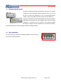
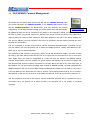
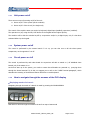
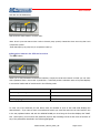
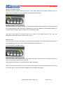
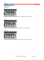
User manual User manual Modular hydronic groups with scroll compressors MUPCO1UEL_REV00_0812_UK Pagina 1 di 11 User manual INDEX 1.1 Advanced electronic ........................................................................................................... 3 1.2 User terminal ...................................................................................................................... 3 1.3 PLD/GENIUS Terminal Management ................................................................................. 4 1.3.1 Unit power on/off.......................................................................................................... 5 1.3.2 Unit power on/off .......................................................................................................... 5 1.3.3 Circuit power on/off ...................................................................................................... 5 1.3.4 How to navigate through the screens of the PLD display .............................................. 5 1.3.5 Language selection (by GENIUS terminal) ................................................................... 9 1.3.6 Machine operation parameters branch ....................................................................... 10 1.3.7 User Branch ............................................................................................................... 10 1.3.8 Alarm table ................................................................................................................. 11 MUPCO1UEL_REV00_0812_UK Pagina 2 di 11 User manual 1.1 Advanced electronic Electronics technologically advanced thanks to the choice of a reliable components, which complexity remains unknown to the user who will be able to control the parameters of the own thermohygrometric welfare, only by the graphic terminal of simple and immediate use. Within the controller have been implemented new features developed specifically by Thermocold for the residential sector and to simplify operations of selection the user interface. The pleasant graphic display mounted on the front of the unit allows to change easily the parameters of the system and ensure the thermohygrometric welfare conditions within the building envelope. 1.2 User terminal The user terminal can display the operating conditions of the unit at any time, and to change parameters. MUPCO1UEL_REV00_0812_UK Pagina 3 di 11 User manual 1.3 PLD/GENIUS Terminal Management The Master unit can operate both with the PLD that with the GENIUS terminal, when you connect physically the GENIUS terminal to the Master, PLD remains frozen until the GENIUS terminal is not disconnected (this only works for the network configuration, for the single machine instead you need to power down and power back). Genius Terminal By GENIUS terminal you can be connected to any device on the network by calling, using the Info button, the mask m_switch_unt_M3 and entering net_address of the unit of interest (to connect to any slave unit is simply pressing the enter key after setting the field which appears to the right of the string "Displays the unit: the net_address”; the only exception is the return on the Master unit that requires pressing the menu key after the enter button). N.B. The connection to all units of the network, with the mechanism described above, is possible not only from the master, but from the generic unit to which the GENIUS terminal (always with address on dipswitch set on 16) is connected physically. The monitoring of the network by the mask m_switch_unt_M3 will no longer be usable if you were to check the fault (in this case, failure means that the unit is no longer seen on the network) of one or more slave units. Infact, when you have the disappeared of a slave unit from the network, the GENIUS terminal connects to the Master unit from whatever the unit to which it was linked to the occurrence of failure and from this time until the drive in failure is resetted it is not longer able to connect to any of the slave units. In this situation, you can still monitor the single slave terminal by GENIUS terminal, connecting physically the GENIUS terminal to the unit of interest after setting the addresses dip-switches of the PGD to i+16, where i is the net address of the device that you want to connect. The foregoing means that for ex. to connect a terminal PGD to the card 2 it must set to its dip-switch the value 18, to the card 3, the value 19 and so on. N.B. The connection to all units of the network, with the mechanism described above, is possible not only by the Master but by the generic unit to which the PGD ( the dip-switch set to 16, always) is connected physically . MUPCO1UEL_REV00_0812_UK Pagina 4 di 11 User manual 1.3.1 Unit power on/off There are two ways of powering on/off of the unit: Power on/off of the system (all the modules) Power on/off of the circuit ( the single unit) The control of the machine state you can do by keyboard, digital input (enabled), supervisor (enabled). The operation on /off, using the ON / OFF button of the keypad has the highter priority. The machine will be able be switched on/off by a supervisor and/or by a digital input, only if it has been activated before by the keypad . 1.3.2 System power on/off The control is performed by the master board: if it is on, you can also turn on all the slave system components, on the opposite if it is off. 1.3.3 Circuit power on /off The control is performed by each slave board: the supervisor will able to switch on / off individual slave boards, only if the master is on. At the first start up of the system, you need to ensure that all boards are powered on, querying them through the shared terminal. To do this, we suggest you to refer to the "USER Terminal paragraph", which describes the meaning of the different buttons and LEDs on used keyboard. 1.3.4 How to navigate through the screens of the PLD display Displaying masks of a branch Navigating through the masks of a branch is made by pressing the DOWN ARROW: that allows to scroll through the masks in the art from top to bottom and MUPCO1UEL_REV00_0812_UK Pagina 5 di 11 User manual and with the UP ARROW key: that shows the same masks in reverse order. Note: On the up arrow button there is also a led with pump symbol; instead the down arrow key led is the compressor symbol . These leds light up at pump and /or compressor start up. Navigation between the different branches The SEL button: allows you to move between the different branches, except the constructor branch in which you can enter with a password from a user mask. In particular a continued pressure maintains active a loop that displays in succession head masks of each branch in the following order: BRANCH HEAD MASK Machine operation parameters branch parameter value "tin" User branch “set1” text I/O displaying branch “d101” text To enter one of the branches, the Sel button must be released as soon as the head mask displays the desired branch . If you want to enter in manufacturer branch you must first enter into the user branch in the in the way explained above and with the ARROW DOWN you must bring the form that displays the "PASS" text . At this point, you must enter the password (equal to 66) according to that are the terms of inclusion of any of the parameters described in the following paragraph. MUPCO1UEL_REV00_0812_UK Pagina 6 di 11 User manual Insert parameters value Parameter inclusion principle provides that from a form which displays the parameter identifier text you enter into the set mask of the same parameter by pressing the PRG button. Pressing the PRG key you get the prompt for the parameter change and the last digit to the right of the field to be changed flashes. After changing the parameter value with the ARROW UP and ARROW DOWN, you must press the PRG button again to confirm the new parameter value. N.B. With a pulse pressure of the SEL button you can return to the display screen of “Tin”, from any identification parameter mask (not set) in which you are. Alarm reset The occurrence of an alarm event that shows itself with the activation of PLD buzzer and at the same time with the displaying of the text mask containing the alphanumeric alarm code. The first pressure of the BELL button: silences the buzzer and displays the alarm code mask, while with a second pressure of the same button you will reset, if the alarm cause has been removed. All the possible alarm codes are reported at “Alarm table” paragraph. Note: To leave the alarm mask, if you are not able to reset (because you have not removed the cause), you can use the SEL key (see above how to navigate among the different branches). MUPCO1UEL_REV00_0812_UK Pagina 7 di 11 User manual Other features ON/OFF key: allows the switching on and off of the unit and it is equipped with corresponding LED. SUN key: allows you to select the chiller mode and it is equipped with corresponding LED. SNOW key: allows you to select the heat pump mode and it is equipped with corresponding LED. MUPCO1UEL_REV00_0812_UK Pagina 8 di 11 User manual 1.3.5 LANGUAGE SELECTION (by Genius terminal) At the start up unit by default displays a form where you can choose the language to use. This screen remains active for 30 seconds, after which the program jump automatically to the main menu (mask M0). You can disable this feature; to do this simply: 1. Go to the Program branch (mask P0) 2. Set the correct password. 3. Go to the Various Parameters subsector 4. Press the down arrow until you get to the mask with reference "R9" 5. Select "N" under "Display Form language." In any case, you can change the language any time. To do this, just to go in the "A2" mask of the key "MAINT". MUPCO1UEL_REV00_0812_UK Pagina 9 di 11 User manual 1.3.6 Machine operation parameters branch This is the branch called at the machine startup and it displays the default T ° evaporator inlet. MACHINE OPERATION PARAMETERS Parameter Tin Tout AI01 AI02 AI03 AI04 CL h CL m 1.3.7 Value T° T° Description Displays the value of B5 Displays the value of B6 Displays the value of B1 Displays the value of B2 Displays the value of B3 Displays the value of B4 Adjust the hours of the clock Adjust the minutes of the clock User Branch The user branch has the following three masks: USER Parameter SET1 SET2 PASS Value T° T° xxxx Description SUMMER SET WINTER SET Construction Password GENIUS Terminal mask S0 which are the selection masks of the summer and winter SET POINT, more manufacturer password mask . MUPCO1UEL_REV00_0812_UK Pagina 10 di 11 User manual 1.3.8 Alarm table All the possible codes are reported below. Note: The alarms present on the PGD terminal and not contained in this table will, in any case, be managed and viewed with their numerical code (e.g. alarm AL036 will show 36). MUPCO1UEL_REV00_0812_UK Pagina 11 di 11