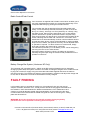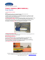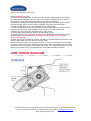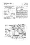
1
Huntsman Game Trailer
Operator and User Manual
Photo used for illustration purposes only
Actual Model may vary from that shown
Promatic International Ltd
Station Works, Hooton Road, Hooton, S Wirral, CH66 7NF, UK
Tel: +44(0)151 327 2220, Fax: +44(0)151 327 7075, E mail: [email protected]
Websites: www.promatic.co.uk, www.promatic.biz
Game Trailer Operator Instructions
SAFETY INSTRUCTIONS
Before connecting this machine to any power source or switching it on, the
user must read these operating instructions carefully.
Clay target launchers can be dangerous and must be treated with great
care at all times to avoid accidents. You must treat a clay target launcher
with the same respect that you would treat a loaded gun.
Never place any bodily part into the path of any mechanical piece whilst
any machine is in motion or likely to be so.
SAFETY FENCING AND GUARDS SHOULD ALWAYS
BE ERECTED AROUND THE MACHINE WHEN IN USE
Assume at all times that a clay target launcher is cocked or loaded and treat it accordingly.
Never approach any machine from the front or sides. Approach only from behind.
ALWAYS disarm ALL machines before carrying out reloading or adjustment.
Reloading with clays should be carried out from the rear of the machines.
Re-arm/cock machines only when all personnel are either behind or at a safe distance
away.
Ensure that all machines are stable and cannot fall over.
Ensure that the machine is sited in a way that will prevent people from being struck by either
the clay in flight, or broken bits of clay being ejected sideways from the machine.
Never allow members of the public or untrained personnel to approach or touch the
machine.
Be aware of the fall zone of both broken and unbroken clays and that changes in wind
direction will affect this. This is particularly important with teal and driven birds.
Never move a cocked/loaded machine. Remove the main throwing spring before transport.
Never place yourself or any bodily part into the path of the casting arm or the clay when the
machine is operating.
Special Hazardous Conditions
In the rare event that the release of the casting arm is blocked or jammed by a piece of clay,
or, in the event of immovable blockage, release the spring by winding the adjusting nut off,
whilst keeping all bodily parts back and away from the spring as it jumps towards the front of
the machine upon release.
Think very carefully about the result that your actions will produce before proceeding.
Promatic International Ltd, Station Works, Hooton Road, Hooton, S Wirral, CH66 7NF, UK
Tele: + 44 (0)151 327 2220, Fax: +44 (0)151 327 7075, E Mail: [email protected]
Web: www.promatic.co.uk
Game Trailer Operator Instructions
INSTALLATION INSTRUCTIONS
In most instances, these machines will not be used in a permanent situation, but whether the
installation is permanent or temporary, the following advice is still applicable.
1. Site the machine in a way, which allows free and un-cramped access all around, paying
particular attention to the ease of disarming/arming and reloading.
2. Ensure that there are no obstructions to the path of the arm and that the machine cannot
change its position due to vibration or reaction.
3. Ensure that the power supply can be easily disconnected.
4. Ensure that cables are laid in such a way that they cannot become entangled in the
mechanism.
5. Ensure that access is only available to the machine by qualified, trained personnel.
6. Although the spring tension can be wound on to the maximum amount possible, it is
advisable to leave at least a couple of mm clearance between the end of the spring and the
locking nut. This will allow the spring to move freely when the machine is fired.
Promatic International Ltd, Station Works, Hooton Road, Hooton, S Wirral, CH66 7NF, UK
Tele: + 44 (0)151 327 2220, Fax: +44 (0)151 327 7075, E Mail: [email protected]
Web: www.promatic.co.uk
Game Trailer Operator Instructions
Trailer Use and Maintenance (UK & Europe)
These instructions are provided to help you to get the best possible service from your trailer. To
ensure that the trailer is used safely, we strongly recommend that the instructions are read by all
users and all the recommendations followed.
Misuse may invalidate warranty
Used correctly and sensibly and maintained to this handbook, your trailer should give many years
of safe and reliable service. If you are in doubt about any of the instructions, please contact our
technical department.
Introduction
Please take the time to read the contents of this manual before you attach the trailer to the towing
vehicle, or attempt to use it. It is a good idea when reading this manual, to take a tour of the trailer
with all persons who will be using it. Make sure everyone responsible is fully conversant with the
procedures for attaching to the towing vehicle, towing, operating and maintaining the unit. By
following, understanding and practising the information and procedures in this manual, your
Huntsman Trailer will give you many miles of safe travelling. Certain information in this manual is
governed by law and is subject to change without prior notice. Great care has been taken to ensure
that the information is correct at the time of publication. However, it is the trailers user‟s sole
responsibility to ensure that they fully comply with all legal requirements.
Legal Considerations For The Un-braked Trailer
This trailer should be used with regard to the Road Vehicles (Construction and Use) Regulations
1986, which state that the towing vehicle must have a kerbside weight of at least twice the gross
weight of the trailer. Therefore, a maximum gross weight of 500kg will only apply if the kerbside
weight of your towing vehicle as stated in the manufacturer‟s handbook is greater than 1000kg.
If the kerbside weight is less than this figure, the maximum gross weight of the trailer will be reduced
accordingly.
Towing Vehicle Suitability
The towing vehicle must be suitable for towing the unbraked trailer. Information on maximum
towing weight can usually be found in the vehicle handbook or stamped on a plate under the bonnet.
If this figure is not available, you MUST obtain confirmation of the maximum allowable unbraked
towing weight from the vehicle manufacturer.
Drivers Licence
Any person wishing to drive a vehicle which is towing a trailer, must be in possession of a current
full driving licence with the correct entitlement. Provisional licence holders are not permitted to
tow a trailer. Make sure that your licence covers you to tow a trailer with your vehicle. For UK licence
holders under normal circumstances a B+E licence is required. If the driver passed his / her test on or
after January 1st 1997 they will have obtained a „B‟ category entitlement only. They are required by
law to take a separate towing test for B+E or CI+E (these categories refer to heavier, braked trailers).
If in doubt, contact your local Police station or see DVLA fact sheet INF30 for further details.
Insurance
Trailers are not required to have insurance unlike your car, however to protect your investment
it would be a wise option to consider separate insurance for the trailer. Some insurance companies
Promatic International Ltd, Station Works, Hooton Road, Hooton, S Wirral, CH66 7NF, UK
Tele: + 44 (0)151 327 2220, Fax: +44 (0)151 327 7075, E Mail: [email protected]
Web: www.promatic.co.uk
Game Trailer Operator Instructions
will automatically extend “third party only” cover onto a towed trailer, however don‟t even take this for
granted, always inform your insurers that you intend to tow to avoid problems later. Your insurance
broker may require trailer details to validate the towing clause on your policy. Some general insurance
companies and other agencies (such as, leisure or trade organisations) offer specialist policies to
cover trailers and equipment carried. The types of policy and cover offered varies and we therefore
advise that you shop around for the most suitable package
Towing Brackets
The towing vehicle must have a properly fitted, good quality towing bracket of the correct specification
for the vehicle and be fitted in accordance with the vehicle manufacturers recommendations. An ISO
Standard 50mm ball should be fitted to suit your trailer. Maintenance of the towing bracket, tow ball
and fixings is most important. Regularly check all mounting nuts and bolts for condition and security. It
is good practice to have the ball inspected by the supplier whenever your vehicle is serviced. If your
vehicle was first registered on or after 1 August 1998 it must be fitted with a tow ball and towing
bracket with approval under EC Directive 94/20/EC Mechanical Coupling Devices. The ball must be
mounted at the correct height for the trailer coupling. When connected, the trailer must sit horizontally
level. Do not tow the trailer if it is tipping backwards or forwards. Always be aware of the condition of
your tow-ball. Keep it well greased and covered when not in use. regularly check the wear indicator
on the coupling head, especially if hiring or using someone else‟s vehicle. If you are in any doubt
about the tow-ball have it replaced.
Vehicle Registration Plate (number plate)
The trailer must display a registration “number” plate whenever used on the road. In the UK a yellow
rear plate must be fitted displaying the registration mark of the towing vehicle. This plate should
conform to the requirements of BS AU 145d:1998, it is not acceptable to substitute the registration
plate with anything else or to omit it. Suitable plates can be made up by motor accessory shops or
motor factors, however please remember that to obtain a number plate you will need some form of
legal identification document (usually a photo card driving licence or passport) and the V5 document
for the vehicle the registration refers to.
Speed and road limitations
The legal limit on normal roads in the UK is 50mph (60mph on motorways and unrestricted dual
carriageways). You are not allowed to tow trailers in lane 3 (or higher) on motorways, unless
specifically directed to do so by a police officer or in an emergency situation (such as to avoid an
accident). Where narrow or restricted traffic lanes are in place at roadworks, motorway or bridge tolls
etc. take note of any sign-posted restrictions that may prohibit trailers from certain lanes, be aware
that tolls may be higher for vehicles with trailers.
Keeping the trailer roadworthy
At the time of writing there is no MOT or equivalent test for light trailers in the UK (most other EU
countries have trailer registration and annual testing). It is up to the user to ensure that his trailer
is kept, and used in a safe, legal and roadworthy condition. To achieve this, the trailer should be
serviced regularly. The frequency of the service will depend upon the amount and type of mileage
covered and the manner in which the trailer is used. An annual service may be sufficient for a trailer
used once a week, whereas if it is used daily a three monthly check is recommended. A service
should include checks on the condition of the whole trailer. If at any time you are concerned about the
condition of any part of the trailer we advise taking it to a trailer dealer to be checked over.
Promatic International Ltd, Station Works, Hooton Road, Hooton, S Wirral, CH66 7NF, UK
Tele: + 44 (0)151 327 2220, Fax: +44 (0)151 327 7075, E Mail: [email protected]
Web: www.promatic.co.uk
Game Trailer Operator Instructions
Attaching The Trailer To The Towing Vehicle
With a front prop-stand fitted
With the towing vehicle and trailer on level ground, make sure the towing vehicle handbrake is fully
applied and the engine turned off. Manoeuvre the trailer towards the rear of the towing vehicle so that
the coupling head is sitting close to but slightly lower than the vehicle‟s tow ball. Grip the coupling
head operating handle with one hand and squeeze the trigger within the handle, then tilt it forwards to
open the mechanism. Lift the coupling head into position and place onto the tow ball, at this point
release the handle and allow it to return to the locked position. To confirm that the head has locked,
try lifting it off the ball without operating the handle. Note. On most UK & European models there will
be a coupling indicator fitted to the front of the coupling, when uncoupled this will have the
appearance of a red plastic plug, when the tow ball is engaged in the coupling this will rise to reveal a
green “correctly coupled” indicator.
With a jockey wheel fitted
If a jockey wheel is fitted turn it‟s operating handle anticlockwise to raise the coupling head to a height
greater than that of the vehicle‟s tow ball. Reverse the towing vehicle towards the trailer so that the
coupling head is directly over the tow ball. Grip the coupling head operating handle with one hand and
squeeze the trigger within the handle, then tilt it forwards to open the mechanism. Using the jockey
wheel lower the head onto the ball, at this point release the handle and allow it to return to the locked
position. To confirm that the head has locked, try lifting it off the ball without operating the handle.
When reversing your vehicle towards the trailer use an assistant to direct you (especially the first
time) take great care to avoid striking the coupling head which could cause damage to towing vehicle
and trailer coupling. Unclamp the prop-stand or jockey wheel and lift it as high as possible before
firmly re clamping, it is good practice to lock the jockey wheel (by fully closing it) and position it with
the wheel parallel to the drawbar.
Always attach the secondary coupling cable
Ideally you should attach the secondary coupling cable to an attachment eye or strong point provided
on the towing bracket, If such an attachment point is unavailable it should be looped over the tow ball
stem. If you do not have a secondary coupling fitted to your trailer, or if it or any part of the coupling
head or operating assembly appear to be damaged or are missing any parts - DO NOT TOW ! Attach
the electrical plug for the trailer lights to the towing vehicle‟s socket ensuring there is enough slack in
the cable for the trailer to correctly negotiate tight turns, without the cable dragging on the road.
Check that all the lights are operating correctly (this is easier to do with an assistant, however it can
be done alone if the rear of the trailer is placed close to a light coloured or shiny surface such as a
garage door where the light reflected from the lamps can be observed by the driver) Check that the
jockey wheel and any secondary prop-stand (where fitted) is raised and securely clamped before
moving off.
Parking The Trailer
Before detaching the trailer from the towing vehicle, you should choose the area where the trailer
is to remain with care. Ideally the trailer should be parked on firm level ground to safeguard
against the trailer rolling or sinking into the ground .Where you have no option but to park on soft
ground, the trailer should rest on suitable scaffold type boards. Always chock the wheels or otherwise
secure the trailer when the trailer is parked independently of the towing vehicle as these trailers have
no hand brake.
Promatic International Ltd, Station Works, Hooton Road, Hooton, S Wirral, CH66 7NF, UK
Tele: + 44 (0)151 327 2220, Fax: +44 (0)151 327 7075, E Mail: [email protected]
Web: www.promatic.co.uk
Game Trailer Operator Instructions
Detaching The Trailer
With the trailer positioned on firm level ground (see parking the trailer for options), apply the towing
vehicle handbrake and switch its engine off. Where the trailer is on un-levelled ground, chock the rear
wheels. Detach the trailer lights power cable plug from towing vehicle‟s socket and place it securely
out of harms way. Release the jockey wheel clamp, lowering the jockey wheel to the ground and
securely tighten the clamp. Release the coupling head as described under coupling the trailer, use the
jockey wheel to raise the coupling head clear of the ball. Finally disconnect the safety cable from its
attachment point.
Cleaning
When working or cleaning under a trailer it MUST be parked on firm level ground, with the wheels
chocked, and the drawbar supported by suitable axle stands.
The underside of the trailer, including all suspension components should be thoroughly washed
down with fresh water after use. Regular cleaning with a pressure washer will help reduce the
risk of premature corrosion, especially where the trailer may be regularly subjected to sea and
road salt or mud and soil.
Powder Coated Finish (Standard)
The main body of the trailer is powder coated to prevent corrosion of steel components. It is an
accepted and effective method of protection against corrosion for steel. However should the coating
become chipped or damaged it is necessary to touch up to ensure long term protection. It is also
important that any deposits of corrosive substances such as road salt, mud, fertilizer and slurry be
removed by immediate washing.
Galvanized Finish (OPTIONAL at extra cost)
Galvanized coatings are present as barriers to prevent corrosion of steel components. It is the
most effective method of protection against corrosion for steel and has the added benefit of giving
excellent wear resistance. The hot-dip galvanizing process produces a coating, which is
bonded metallurgically to the steel, a unique feature in coating processes. During the initial
months of exposure to the atmosphere the outer surface weathers, converting the original shiny
surface colour to a matt, dull grey protective coating. During this period it is important that any
deposits of corrosive substances such as road salt, mud, fertilizer and slurry be removed by
immediate washing. Failure to do so will lead to discolouration and unsightly staining of the surfaces.
Once formed, the galvanized coating will provide protection against corrosion for many years.
Long Term Storage
If the trailer is to be put into storage, it is recommended that the axles are supported on suitable
stands with the wheels clear of the ground. This will prevent the tyres from suffering permanent
distortion if they should lose pressure. It is recommended that the trailer is stored in a dry building
and before the trailer is put back into use on the road, it should be fully serviced.
Personal safety
Whether loading or unloading the trailer, cleaning it or carrying out routine / periodic maintenance
procedures, always wear personal protective equipment to suit the task you are performing i.e.
Always wear gloves when handling ropes or loading rough or coarse objects.
Whenever loading or unloading a trailer be aware of other people in the immediate area.
Promatic International Ltd, Station Works, Hooton Road, Hooton, S Wirral, CH66 7NF, UK
Tele: + 44 (0)151 327 2220, Fax: +44 (0)151 327 7075, E Mail: [email protected]
Web: www.promatic.co.uk
Game Trailer Operator Instructions
Tyre care
Fully inspect each tyre (including the spare if fitted) for tread depth (tyre wear regulations for trailers
are the same as those for cars, 1.6mm minimum) and uneven / excess wear. Pay special attention
to the tyre sidewalls, looking for nicks, abrasions and cuts. If you suspect a tyre is unsafe or below
the legal requirements, ask your local tyre retailer to inspect the tyre. Check tyre pressures regularly
with the tyres cold and inflate as necessary. DO NOT be tempted to inflate the tyres to a higher
pressure than stated on the tyre wall as this will lead to excessive tyre wear and trailer instability.
Under-inflation will adversely affect the handling and fuel consumption and will lead to premature tyre
wear. If seriously underinflated a tyre will overheat and fail very rapidly. As the trailer may get much
less use than your car, this means the tyres also get less wear, pay particular attention to the
condition of the rubber surface as tyres on very lightly used trailers can perish due to old age before
they are anywhere near worn out.
Tyre pressures:
5.00 - 10 36 p.s.i. / 2.5 bar
Tyre Repairs
Punctured or damaged tyres should be inspected and repaired or replaced by a specialist tyre
distributor. The tyres are tubeless and the fitting of inner tubes is not recommended. Defective
tyres must be replaced immediately and must not be used on the public highway. When replacing
a tyre, make sure that it is of the correct size, type and specification. Never fit remoulds, regrades
or second hand tyres to this trailer. Have the wheels balanced and always request that a
new valve be fitted. Any wheel rims that have been damaged by striking a kerb or similar object
should be replaced as soon as possible.
Wheel nuts on new trailers
Check wheel nuts after first 25 miles of service and subsequently before every journey, the correct
wheel nut torque is shown in the section below.
Removing and re-fitting Wheels
Position the trailer on a firm level surface, apply the towing vehicle handbrake firmly and if possible
chock the other trailer wheel. Using a 18mm socket or wheel brace, slacken each wheel bolt by a
maximum of half a turn. A suitable jack should be placed under the trailer cross member close to the
axle. Remove all four wheel nuts whilst supporting the wheel. Place the bolts somewhere safe until
refitting a wheel. Lift the wheel into place aligning the wheels holes with the wheel studs. Tighten each
bolt by hand following the sequence shown. Lower the trailer to the ground, remove the jack and fully
tighten all the wheel bolts, following the sequence shown. The wheel bolt threads and seating surface
should be clean and free from oil or grease. If a torque wrench in not available, then either a standard
socket bar or wheel brace (approximately 300mm / 12” long) should be used to prevent over
tightening. Do not use foot pressure on the wheel brace or the extra force available from an extension
bar. Have the nuts reset to the correct torque as soon as possible afterwards. The correct wheel bolt
torque (42 lb/ft or 56.9Nm) Great care should be taken to ensure that all persons are kept clear of the
trailer while the wheel is changed or until adequate support stands are in place under the axles
All wheel bolts should be checked for correct tightness after the first 25 miles of travel.
Tightening sequence 1, 3,4, 2 (Diagonally Top to Bottom)
Promatic International Ltd, Station Works, Hooton Road, Hooton, S Wirral, CH66 7NF, UK
Tele: + 44 (0)151 327 2220, Fax: +44 (0)151 327 7075, E Mail: [email protected]
Web: www.promatic.co.uk
Game Trailer Operator Instructions
Maintenance
Coupling head
The general condition of the coupling unit should be checked monthly. Any damaged or worn parts
should be replaced immediately. To minimize wear on your towing ball and coupling head, clean out
the cup in the coupling head monthly and apply new grease.
Every 3000 miles or 6 months, thoroughly examine all moving parts for wear and correct functioning
and check for excessive wear on the coupling head and coupling
Note. If you need to replace your coupling unit your tow ball may need to be replaced as well due to
the extra wear that may have occurred.
It is always recommended that the coupling unit and ball are replaced at the same time, as this will
increase the service life of both components.
When replacing the coupling unit, the attachment bolts and nuts should also be replaced.
Wheel bearings & hubs
Taper roller types: Taper roller bearings require a small amount of play to operate efficiently, this play
is taken up as the bearings warm up and it is necessary to leave this pay in the system when
replacing or adjusting the bearings. After the first 500 miles and at intervals of 1500 miles or every 6
months examine the wheel bearing hubs for excessive side play, adjust and/or re-grease if necessary.
Adjustment: Remove the knock-in grease cap (if it appears to be very tight it may be freed by lightly
tapping around the edge)
Carefully remove the split pin and tighten the nut until the free rotation of the hub is impaired.
Slacken the nut by approximately 1/12 of a turn (about 30 degrees) until the next groove in the nut is
aligned with the drilled hole, refit the split pin (or fit a new one if badly damaged or deformed) and
splay to secure the nut. Refit the grease cap and test spin to ensure the hub is free to rotate.
Damaged, loose or missing hub caps should be replaced as soon as possible.
Axle & suspension
No lubrication is necessary.
General Lubrication
All other moving parts should be lightly oiled regularly, using a good general purpose oil.
Promatic International Ltd, Station Works, Hooton Road, Hooton, S Wirral, CH66 7NF, UK
Tele: + 44 (0)151 327 2220, Fax: +44 (0)151 327 7075, E Mail: [email protected]
Web: www.promatic.co.uk
Game Trailer Operator Instructions
Trap Use and Maintenance
OPERATING INSTRUCTIONS
HUNTSMAN/SUPER SPORTER (All Models)
BEFORE MAKING ANY ADJUSTMENTS OR WORKING ON THE TRAPS
ENSURE THAT THE TRAPS ARE UNCOCKED AND SWITCHED OFF
Check visually from the rear of the machine(s) that the motion of the casting arm(s) is not
restricted or blocked in any way.
Always operate only from the REAR and NEVER from the front or sides. From this stage on,
do not lean on the machine(s) OR touch whilst in motion.
Check the trip/isolator(s) on the side of the control box are in the “OFF” position, so that the red
telltale(s) are visible.
Check that ALL switches on the operators panel are in the centre OFF position.
Make the battery connections ensuring that the red and black cables of each pair are connected to
the same battery. With the fitted quick release battery connections it is essential NOT to hammer the
connections on or to over tighten them.
Promatic International Ltd, Station Works, Hooton Road, Hooton, S Wirral, CH66 7NF, UK
Tele: + 44 (0)151 327 2220, Fax: +44 (0)151 327 7075, E Mail: [email protected]
Web: www.promatic.co.uk
Game Trailer Operator Instructions
Switch the trip/isolator(s) on the side of the control box to the “ON” position, so that the red
telltale(s)are not visible.
Selecting each machine in turn and from the back of the machine(s) push the arm/off/disarm toggle
switch into the “DISARM” position for about half a second only and release it. The switch is springloaded and will return automatically to the “OFF” position.
The casting arm(s) should now be static and visible to the left side of the machine(s) and the
machine(s) will be in a safe condition. If the casting arm(s) are not visible, repeat the previous step
until the arm(s) are visible. and the machine(s) are in a safe condition.
Switch the trip/isolator(s) on the side of the control box to the “OFF” position, so that the red telltale(s)
show.
If your machine has been supplied ready for operation, then proceed to the next instruction.
If your machine is supplied without its carousels fitted, they will need to be fitted using
the centre pin, nut and washers provided on the top plate. Tighten the 19mm nylock nut
down on to the blue plastic damping spacer. The nut should be tight enough for the carousel(s)
to turn but not spin freely. It is best to keep turning the nylock until the blue damping spacer
starts to squash up slightly.
If your trap was delivered without its mainspring fitted, now is the time to fit it. The
Arm(s) can now be moved by hand until they stick directly out of the front of the trap away from
the operator. The mainspring would now normally be at its shortest length and can therefore
be fitted to the machine. See following photo.
DO NOT LOAD CLAYS YET.
Promatic International Ltd, Station Works, Hooton Road, Hooton, S Wirral, CH66 7NF, UK
Tele: + 44 (0)151 327 2220, Fax: +44 (0)151 327 7075, E Mail: [email protected]
Web: www.promatic.co.uk
Game Trailer Operator Instructions
Ensure that nothing will restrict the further motion of the arm(s).
Switch the trip/isolator(s) on the side of the control box to the “ON” position, so that the red
telltale(s)are not visible.
Switch the arm/off/disarm toggle switch(s) down to the “ARM” position.
The machine(s) will cycle and stop in the armed position and MUST BE TREATED WITH
EXTREME CAUTION.
It is now necessary to fire the trap but NOT allow it to re-cock so that clays can be loaded.
This is done by pushing the arm/off/disarm toggle to the “DISARM” position for about half a second
and release it so that it returns to the “OFF” position as before.
The trap will immediately fire but not re-arm. The throwing arm will be visible and stationary
on the left hand side of the machine.
The machine is now in the disarmed or SAFE state.
To further remove the risk of accidental re-cocking, it is advisable to switch the trip/isolator(s) on the
side of the control box to the “OFF” position, so that the red telltale(s) are visible.
(Remember to switch back on after loading clays! This is often forgotten in the rush to re-load
during shoots.)
The magazine can now be filled and it is advisable to place only a small quantity of clays in
each column initially.
Ensure that the clays about to be thrown are going into a safe area.
Switch the arm/off/disarm toggle switch(s) down to the “ARM” position. The machines will load a clay
and come to the cocked position and are now ready to fire.
To check for clay flight and direction, fire the traps using the arm/off/disarm toggle switch exactly as
before so that the machine fires ONCE but does not re-arm until the switch is returned to
the “ARM” position.
With the trap(s) in the DIS-ARMED/SAFE position, switch the trip/isolator(s) on the side of the control
box to the “OFF” position, so that the red telltale(s) are visible. Move to the rear of the machine to
adjust the direction of the clay flight to suit and elevation if required as follows.
ANGLE ADJUSTMENT
DTL (Front) trap(s) as fitted to the Huntsman Range have additional control motors to allow the trap(s)
to oscillate from side to side and on ABT (Rear) trap up and down as well. The amount of angle can
be adjusted as follows.
Loosening the clamping nut(s) on the elevation slot bolts on the Front 2 machines will allow you to
adjust the height and angle of elevation, once correctly set, tighten the nut on the height-adjusting slot
lightly. See photo below.
Using a 10mm Allen key undo the crank bolt, situated on the oscillating disc on the small gearbox,
bolted to the trailer frame between the front traps and remove from the hole in the disc. See photo
below. The disc has several 12mm threaded holes in it spiralling out from the centre of the disc. The
further out the hole the greater the angle of oscillation. Put the crank bolt back in to the required hole
and tighten.
Promatic International Ltd, Station Works, Hooton Road, Hooton, S Wirral, CH66 7NF, UK
Tele: + 44 (0)151 327 2220, Fax: +44 (0)151 327 7075, E Mail: [email protected]
Web: www.promatic.co.uk
Game Trailer Operator Instructions
The front 2 traps are tied together with a tie rod (seen at the bottom of the picture above) which has
been factory set but can be adjusted to allow a greater spread of clays. Caution should be exercised
to ensure that the tie rod is not over adjusted to enable the mounting bolts to hit the trailer frame.
On the rear ABT trap there is an extra control motor fitted for up and down movement. See
photo below.
By placing the crank bolt in a different hole on the disc the angle of elevation can be adjusted.
The further out the hole from the centre on the disc, the more up and down movement is
achieved.
Promatic International Ltd, Station Works, Hooton Road, Hooton, S Wirral, CH66 7NF, UK
Tele: + 44 (0)151 327 2220, Fax: +44 (0)151 327 7075, E Mail: [email protected]
Web: www.promatic.co.uk
Game Trailer Operator Instructions
The rear trap also has a separate control motor bolted to the trailer frame below the rear trap for
oscillation, again adjustment is made using a 10mm Allen key to undo the crank bolt, situated on the
oscillating disc on the small gearbox, and remove from the hole in the disc. See photo above. The
disc has several 12mm threaded holes in it spiralling out from the centre of the disc. The further out
the hole the greater the angle of oscillation. Put the crank bolt back in to the required hole and tighten.
The oscillating control switches on the Front and Rear traps have three positions. The
centre position is the “off” position. The forward momentary position is for inching the
machine a few degrees at a time (enabling static targets) and the rear “on” position holds the motor
on so allowing the oscillating motor to oscillate continuously while the machine is in use.
Note that when in the “on” position the oscillating motors will run and then stop momentarily
before restarting. This feature is fitted to all machines with oscillating motors as it carries out
two functions. The first is to randomly stop and start the oscillating motors so making it
impossible for the shooter to “read the target” or guess which direction the next target is
going in if the trap is hidden from view. The second function is to stop the oscillating motors
after a short period of time if the machine is not being used so saving battery power. This
means that the user does not have to walk up to the machine and turn it off when shooting
has finished, the timer will do this automatically. When the next target is called for and the
trap fired, the timer starts the oscillating motors again. Even if the oscillating motors have shut down,
users must be aware that the machine(s) are still armed and must only be approached from behind to
disarm the machine(s) before reloading or adjusting. Inch control automatically bypasses the timer
unit which means that the oscillating motors will continue to oscillate until they are switched off at the
operators control box.
The elevation control switch on the Rear traps also has three positions. The centre position is the “off”
position. The forward momentary position is for inching the machine a few degrees at a time (enabling
static targets) and the rear “on” position holds the motor on so allowing the elevating motor to run
continuously while the machine is in use. Note that when in the “on” position and like the oscillating
motors above, the elevation motor will run and then stop momentarily before restarting. Even if the
motor has shut down, users must be aware that the machine(s) are still armed and must only be
approached from behind to disarm the machine(s) before reloading or adjusting. Inch control
automatically bypasses the timer unit which means that the elevation motor will continue to run until
switched off at operators control box.
Once the above adjustments have been finalised, you are now ready to fill the magazine if required.
Should the clay have a tendency to peel off, either left or right of stable flat flight, this can be
adjusted by raising the trailer on one side to compensate and bring the flight level.This method may
be necessary for machines situated on uneven ground.
All Super Sporter traps have an adjustable rear clay guide rail on the casting plate. By slackening and
moving this rail either forward or backwards by small increments, and then re-tightening, it is possible
to adjust the direction of throw of the clay by up to 30° without moving the complete machine. It is not
recommended that this facility be used in temporary sporting settings.
ADJUSTMENT FOR DISTANCE AND SPEED
Increasing or decreasing the distance that the clay is thrown is achieved by winding tension on or off
the spring(s). This MUST be done with the trap(s) in the disarmed/safe condition. After adjustment of
the main spring to set the correct throwing distance,the nuts on the spring stud must be tightened
against each other.The trap(s) can now be switched on for normal use by pressing the arm/off/disarm
toggles down to “ARM” to cock the machine.The trap(s) will fire and re-cock each time that the fire
button on either the operators control box or radio remote is pressed. No loading or adjustment to the
machine should be carried out unless the machine is disarmed/safe. After use, the machine must be
left in the disarmed/safe condition and the power supply removed. It is not necessary to relieve the
remaining spring tension.
Promatic International Ltd, Station Works, Hooton Road, Hooton, S Wirral, CH66 7NF, UK
Tele: + 44 (0)151 327 2220, Fax: +44 (0)151 327 7075, E Mail: [email protected]
Web: www.promatic.co.uk
Game Trailer Operator Instructions
Radio Control/Flush Control
Your Huntsman is supplied with full radio control which enables you to
use each individual trap manually, any 2 traps simultaneously or ALL
3 traps simultaneously by pushing the relevant buttons.
The controller also has as standard a fixed 20,40 & 60 bird flush
facility. To use this facility first select the flush you wish to shoot 20
bird (1 or 2 Guns), 40 bird (2 or 3 Guns) 60 bird (3 or 4 Guns), using
the slider control. Set the Flurry speed knob in the centre position
(used to slow down or speed up the time between clay launches).
Push and hold down the start knob for 2 seconds when a Beep will be
heard, indicating that the Flush will commence in 3 seconds. Once
started the Flush will automatically continue until the selected amount
of birds have been thrown, which will be indicated by another audible
beep from the handset, the speed of the Flurry can be adjusted whilst
in operation if required. To abort a flush once commenced, simply
push and hold down the start knob for 2 seconds.
The handset is powered by a 9 volt battery, which can be changed by
removing the rear cover to allow access.
Should the battery fail during a shoot, the trailer can be used by
manually firing the traps using the relevant FIRE pushbuttons on the
operators control box.
Battery Charge Bar System (Huntsman XP Only)
The Huntsman XP is supplied with 5 x 10⁵Ah 12volt DC Lead Acid batteries and an Automatic
Charging system fitted, the system consists of a number of intelligent chargers which enable the user
to plug into a mains AC supply using the removable mains lead supplied and leave the trailer to
recharge overnight. The intelligent chargers monitor the battery conditions and adjust the charge rate
to suit, with an automatic cut out when the batteries are fully charged.
FAULT FINDING
It is Promatic‟s policy to upgrade or modify any of its products if they are ever proved
suspect. Problems, which do occur, usually revolve around the clay pigeons themselves or
the variation in their sizes between the different manufacturers. Poor maintenance and
cleaning or physical damage caused during transportation of the machine are the other
normal causes. Items that should be treated with great care are the throwing arm, casting
plate and electrical box.
WARNING: At no time should you put yourself at risk by placing any bodily
part within the area of operation of moving mechanical parts.
Promatic International Ltd, Station Works, Hooton Road, Hooton, S Wirral, CH66 7NF, UK
Tele: + 44 (0)151 327 2220, Fax: +44 (0)151 327 7075, E Mail: [email protected]
Web: www.promatic.co.uk
Game Trailer Operator Instructions
FAULT FINDING (ELECTRICAL)
Super Sporter as fitted to Huntsman Range
Electrical Schematic
1. Machine does not cock (i.e. come to the loaded position.)
Check:
(a) Battery is charged and that connections are tight.
(b) Magnetic trip switch is in the “ON” position.
(c) Toggle switch is in the down “ARM” position.
(d) Arm is clear of roller limit switch under casting plate. If not, then press toggle up to
“DISARM” until the arm is clear, then back down to the “ARM” position.
2. Machine still does not cock.
(a) Check all connections are tight including those inside the electrical box. Check for
broken wires and damaged connections.
(b) If there are no broken connections (battery connected, all switches on) press toggle up
to “DISARM”, listen and watch for the 12v relay operation in the control box.
(c) If the relay operates but the motor does not turn - short across the 2 large contacts
on the relay with a screw driver or piece of wire.
If the motor does not turn - then the motor is suspect. If the motor does turn - then the relay
is faulty. Contacts may be dirty or worn out.
(d) If the relay does not operate - short across contacts on back of trip switch on Super
Sporter models.Try toggle switch in “DISARM” and “ARM” positions.
If the motor turns - then the trip switch is faulty.
Promatic International Ltd, Station Works, Hooton Road, Hooton, S Wirral, CH66 7NF, UK
Tele: + 44 (0)151 327 2220, Fax: +44 (0)151 327 7075, E Mail: [email protected]
Web: www.promatic.co.uk
Game Trailer Operator Instructions
(e) If the motor does not turn - then short the brown wire to the yellow/green wire on the
back of the toggle switch with the switch in the “DISARM” position.
If the relay operates and the motor turns - then the toggle switch is
faulty.
If the relay still does not operate then it is faulty.
3. Machine runs in “DISARM” position, but not in “ARM” position.
(a) If the arm is clear of the roller limit switch then the roller limit switch is faulty.
Check that the roller arm is not seized. If so, strip, clean and
re-assemble. Otherwise replace the switch.
4. Machine cocks, but will not fire on Radio Handset.
(a) Either the connections, Receiver or Handset are faulty. Replace the battery in the Handset if the
trap still does not fire, remove the lid from the receiver and check that the power on LED is
illuminated, if not remove the lid of the main control box and check the radio supply fuse. If the fuse
has blown replace, if the fuse continues to blow or the fuse is not blown the radio is faulty and should
be returned to Promatic for repair.
5. Trap fires by itself!
(a) Disconnect the radio receiver and switch the trap back on.
If the trap cocks normally - then the radio is damaged or shorted out.
Alternatively, the push button switch is stuck in or faulty.
(b) If the trap continues to fire - then check the arm to crank timing relationship as
described further on in this manual. If the above relationship is correct then, after
having put the trap into the disarmed/safe position, move the roller limit switch
away from main frame along the slotted bracket to its maximum. If the machine now
cocks normally - then move the limit switch back to within 5mm of its original position. If
the trap now fires by itself again then move the switch to 10mm of its original position
and so on until the trap cocks normally under all conditions.
(c) If the machine still fires by itself - check if the relay contacts have
stuck together, and if so replace. If the relay operates correctly, but the trap still fires by
itself, then the roller limit switch is faulty and should be replaced.
Promatic International Ltd, Station Works, Hooton Road, Hooton, S Wirral, CH66 7NF, UK
Tele: + 44 (0)151 327 2220, Fax: +44 (0)151 327 7075, E Mail: [email protected]
Web: www.promatic.co.uk
Game Trailer Operator Instructions
FAULT FINDING (MECHANICAL)
Super Sporter
1. Carousel does not rotate.
Check:
(a) The Carousel pusher arm is not jammed with broken clays or dirt.
(b) The pusher return spring is broken or missing.
(c) With the pusher arm withdrawn, the carousel should be free to rotate with a small
amount of friction. This is adjusted by tensioning the locking nut holding the carousel
on against the plastic sleeve underneath it.
(d) Carousel pusher timing is correct, i.e. when the gearbox crank and connecting rod are
in line at maximum extension, (see photo below) the rollers on the bottom of the
carousel pusher arm should be 1 mm clear of the carousel plate at maximum travel. If
this is not the case then the clamp on the rear pusher shaft should be adjusted
accordingly. It must be tightened before operation of the machine.
2. Machine will not throw clays.
It is usually obvious what is wrong with a machine which does not throw clays at all. It is
more likely that the following situation arises:
Machine throws clays but:
(a) The clay flicks up in the air.
The arm is probably bent down or the casting plate bent up, squeezing the clay
between them. The arm or plate should be replaced or straightened.
(b) The clay goes no distance (even though the main spring is wound up tight).
The arm is probably bent upwards causing clay to go under it at its tip. This will also
cause clays to break. The solution is to straighten the arm.
(c) The clays are inconsistent in direction.
Promatic International Ltd, Station Works, Hooton Road, Hooton, S Wirral, CH66 7NF, UK
Tele: + 44 (0)151 327 2220, Fax: +44 (0)151 327 7075, E Mail: [email protected]
Web: www.promatic.co.uk
Game Trailer Operator Instructions
The clay is being jammed under the arm towards the end. This is usually caused either
by the arm being bent down, then the tip bent up or more likely clays varying in
thickness. The solution if the arm is bent is to straighten it. If it is the clay thickness,
then lower the casting plate to accommodate the thickest one you can find. Adjust
each nut exactly the same amount, until 1 to 1.5 mm clearance is achieved between
the bottom of the friction strip and the clay. See photo above.
3. The Machine breaks clays!
A point to consider here is that if you have other traps, which have suddenly started to break
clays, then it is probably the clays, which are at fault. Particularly soft clays can be
accommodated, by fitting a “soft fall” plate to the machine (all machines manufactured after
January 98 are fitted with a soft fall plate), but sometimes the clay will be unable to absorb
the actual throwing forces consistently. The maximum acceptable level of no birds is 5%, but
should in practice be less.
A simple process should be followed which differentiates between the loading of the clay
prior to throwing and the throwing of that same clay.
Check loading cycle first:
(a) Check that clays in the magazine are intact, not chipped or cracked. If in doubt, remove
suspect clays and refill with ones known to be intact.
(b) With the machine switched “OFF”, rotate the magazine by hand, removing each clay
as it drops onto the casting plate. Check for cracks and chips. If the clays arrive on the
plate intact, then move
on to the throwing section below.
(c) If they arrive chipped or cracked then remove the magazine and check that the thickest
clay you can find slides easily under both inner and outer knife edges, i.e. just free
enough not to be squeezed onto the carousel plate. Check of course that the knifeedges
are not excessively high, although this would tend to shave the bottom off the
next clay, not break it. Adjust both knife-edges accordingly.
(d) If damaging contact occurs on all columns then the knife-edge is damaged and must
be realigned by refitting or possibly filing or grinding to give minimal clearance.The
knife-edges are adjustable with a 10 mm spanner. Each knife-edge has three slotted
holes for ease of adjustment.
(e) Check each clay and if all are unchipped or uncracked, remove the cloth and repeat
the process. This time if any of the clays break or crack as they land on the casting
plate, then the clay is unsuitable or too soft.
(f) Check that there are no tight spots in any of the carousel pockets. Occasionally
machines can suffer slight damage in shipping to the carousel. This can be easily
adjusted with a suitable piece of wood or the handle of a hammer. See photo below.
Ensure that a handful of clays move up and down each of the pockets once adjusted. If
the clays arrive on the plate intact, then the fault lies in the throwing cycle.
Promatic International Ltd, Station Works, Hooton Road, Hooton, S Wirral, CH66 7NF, UK
Tele: + 44 (0)151 327 2220, Fax: +44 (0)151 327 7075, E Mail: [email protected]
Web: www.promatic.co.uk
Game Trailer Operator Instructions
Check throwing cycle next:
(a) Check arm for straightness, for chunks missing from the rubber/plastic friction strip or
any other physical damage to the arm. If the arm cannot be straightened then it should
be replaced. A new friction strip can be fitted to an old arm if necessary.
(b) Check for damage to the casting plate especially the front edge of the plate in case it
has been dented, bent or burred. Check for flatness; ensure that no screw heads
protrude and that there are no other obstructions to the clay‟s path.
(c) Check the height of the arm over the plate across its whole surface to ensure that the
clay fits under the friction strip with about 1 mm clearance. Any more than 3 mm
clearance will cause the arm to break the clay by riding over it.
(d) Check that the bolt holding the arm to its clamp block is tight.
(e) Check the arm-crank timing relationship. If this relationship is incorrect the trap will
definitely break clays when throwing. The timing can be adjusted to the diagram
found in this manual.
As each of the above elements is checked, something incorrect should be discovered. If the
machine still breaks clays, then there is one final check.
Slacken the main spring to its minimum extension, i.e. with the throwing arm in the forward
position the coils are just open. Operate the trap a few times in this mode, which puts hardly
any stress into the clay because of the slack mainspring. If the clays still break then it is very
likely that the actual clays are sub standard and a new batch should be obtained.
ARM TIMING DIAGRAM
Promatic International Ltd, Station Works, Hooton Road, Hooton, S Wirral, CH66 7NF, UK
Tele: + 44 (0)151 327 2220, Fax: +44 (0)151 327 7075, E Mail: [email protected]
Web: www.promatic.co.uk
Game Trailer Operator Instructions
Instructions for Fitting a Midi Carousel
1. With the trap disarmed and the carousel empty of clays, remove the standard carousel
from the machine. This is done by unscrewing the 19mm nylock nut in the centre of the
carousel.
2. With the carousel removed take a 10mm spanner and unscrew the outer knife-edge
assembly from the top plate. Look at the underside of the top plate to establish which
two bolts hold the assembly to the top plate.
3. Refit the complete knife-edge assembly over the inner fixing holes on the top plate.
4. Drop the midi carousel on to the top plate shaft but do not fit the 19mm nylock nut and spacer.
5. Put a midi clay into one of the carousel pockets (it does not matter which one) and
rotate the carousel so that the clay passes through the knife-edges. The clay must
pass through the inner and outer knife-edges without the drive-band of the clay
catching on the side of either knife blade. If the clay does catch on either blade, the
blade will need to be adjusted. It is possible to move the blades away from the clay as
all blades have slotted holes machined in them. Slacken off the bolts that hold the knife
blade to the block and then slide the blade in the direction required. Retighten the
fixing bolts when the blade is in the correct position.
6. With the clay passing cleanly through the knife-edge blades, stop the clay under the
leading edges of the knife blade and check that the blades are at the correct height.
Adjust as necessary with a 10mm spanner.
7. Fit the carousel blue spacer and 19mm nylock nut and retighten, so that the carousel
does not spin freely when it turns. There needs to be a small amount of friction when
the carousel rotates. The carousel does not need to be set in any particular position, it
will automatically time itself.
8. The carousel is now ready to be filled with clays.
Promatic International Ltd, Station Works, Hooton Road, Hooton, S Wirral, CH66 7NF, UK
Tele: + 44 (0)151 327 2220, Fax: +44 (0)151 327 7075, E Mail: [email protected]
Web: www.promatic.co.uk
Game Trailer Operator Instructions
INSTRUCTIONS FOR SPRING REMOVAL
The instructions below apply to the Super/Sporter models.
1. Ensure the machine is sited in a way, which allows free and un-cramped access all
around, paying particular attention to the ease of disarming/arming and reloading.
2. Ensure that there are no obstructions to the path of the throwing arm and that the
machine cannot change its position due to vibration or reaction.
3. Disarm the machine using the arm/disarm toggle switch and make safe before
removing any clays from the carousel.
4. From behind the machine, press the arm/disarm toggle switch down to arm the
machine. The throwing arm will rotate to the armed position. In this condition the
machine must be treated with extreme caution.
5. The next step is to disarm the machine, but only hold the toggle switch in the disarm
position just long enough for the trap to fire. Release the toggle switch immedliatley so
that the rectangular block (the rectangular block has a long crank bar connected to it
with a 10mm cap head bolt) on the gearbox output shaft stops in the 11.00 o‟clock
position. The 11.00 o‟clock position is when viewed from behind the machine looking
down on the gearbox itself.
6. If the rectangular block is pointing to 12.00 o‟clock flick the arm/disarm toggle switch
momentarily just enough to allow the block to point to the 11.00 o‟clock position.
7. If the rectangular block is pointing to 10.00 o‟clock, rearm the machine and then
disarm again.
8. Disconnect the battery from the machine once the block is in the correct position.
9. With the rectangular block now pointing to the 11.00 o‟clock position, the throwing arm
can be pushed slowly around anti clockwise by hand. It is important to push only on
the end of the throwing arm. With the machine disarmed the throwing arm will have
stopped at somewhere between 8.00 and 7.00 o‟clock. When pushing the arm by hand
the spring will take over when the arm gets to about 6.00 o‟clock, at this point it is
advisable to hold on to the arm so that it gently stops at the 5.00 o‟clock position. It is
the 10mm cap head bolt on the rectangular block that stops the arm at 5.00 o‟clock,
which in turn stops the arm from firing. This is why it is important to only carry out step
9 when the rectangular block is pointing to the 11.00 o‟clock position.
10. Reconnect the battery to the machine and hold the arm/disarm toggle switch to the
disarm position long enough until the throwing arm has moved and is pointing to the
12.00 o‟clock position directly in front of the machine.
11. With the throwing arm sticking out in front of the machine, the spring can now be
removed by undoing the locking nuts with two 19mm spanners.
12. When refitting the spring, wind tension on until, with the arm fully forward, the coils
have at least 0.5mm gap between them. Tighten the two 19mm locking nuts to the
mainframe so that the spring can‟t vibrate loose.
Promatic International Ltd, Station Works, Hooton Road, Hooton, S Wirral, CH66 7NF, UK
Tele: + 44 (0)151 327 2220, Fax: +44 (0)151 327 7075, E Mail: [email protected]
Web: www.promatic.co.uk
Game Trailer Operator Instructions
SPORTER 400TT & SUPER SPORTER SPARE PARTS
Number
New Part No
Description
1
2
3
4
5
6
7
7
7
8
9
10
10
10
11
12
13
14
15
16
17
18
19
20
21
22
23
24
25
26
27
28
29
30
31
32
HR/2010
HR/2100
RN6/2100
HR/3350
RN6/2200
RN6/3500
RN8/1140
SP8/1140
SSP10/1140
RN6/2500
RN8/3400
RN8/4200
SP8/4200
SPIDA/4200
RN6/2630
RN6/2600
RN8/3150
RN6/3200
SP8/4375
B00V/SET1
D04N/RN38
S02Z/037D6
B06V/BF202620
D04N/RN25
RN6/3250
RN6/3300
RN6/3030
E11V/83850
RN6/3440
RN6/7210
SP8/4050
M02V/BR113
M03V/MV50R50 NMRV50
E00V/SP8
E00V/SSP8
E00V/RN8US
Arm Complete (L/Cut)
Arm (L/Cut)
Arm (Cast)
Soft Fall Plate
Friction Strip
Teal Finger
Rear Pusher Shaft (400TT)
Rear Pusher Shaft (Sporter 8)
Rear Pusher Shaft (Sporter 10)
Arm Clamp Block
Let Down Ramp
Rear Pusher Clamp Block (400TT)
Rear Pusher Clamp Block (Sporter 8)
Rear Pusher Clamp Block (Sporter 10)
Spring Roller
Main Shaft
Outer Knife Edge
Outer Knife Edge Block
Bearing Sleeve (Sporter)
Bearing Set 1 (400TT)
Main Shaft Spacer
Rear Pusher Spring
Phos. Bronze Bushes
Rear Pusher Rollers
Inner Knife Edge
Inner Knife Edge Block
Rear Top Plate Supports (400TT)
Roller Switch
Backrail
Roller Switch Bracket
Gearbox Shaft
12v Motor
50:1 Gearbox
Electric Box (Sporter)
Electric Box (Super Sporter)
Electric Box (400TT)
For more information please see Main User Manual or call Promatic
Promatic International Ltd, Station Works, Hooton Road, Hooton, S Wirral, CH66 7NF, UK
Tele: + 44 (0)151 327 2220, Fax: +44 (0)151 327 7075, E Mail: [email protected]
Web: www.promatic.co.uk
Game Trailer Operator Instructions
DTL/ATA & ABT/WOBBLE SPARE PARTS
Number
New Part No
Description
1
2
3
4
5
6
7
8
9
10
11
SP1A/2010
SP1DA/1180
SP1DA/1140
OT8/4608
OT8/4618
SPIDA/4620
S02Z/031D7
SPIDA/4604
S03Z/14 X 10 X096
SPIDA/4607
RN6CA/4100
RNPW/4100
SPIDA/4100
E12V/BEN12
SPIDA/4606
RN6CW/4125
RNPW/4125
M02V/MP080
SPIW/4125
M03V/MV40R80
M03V/MV40R60
M02/MP102
M03V/MV50R80
M03V/MV50R60
M03V/MV50R100
Arm Complete ( Laser Cut )
Rear Pusher Top Half
Rear Pusher Shaft
Solenoid Trigger
Solenoid Bracket ( OT )
Solenoid Cradle
Solenoid Return Spring
Solenoid Bracket ( Sporter )
Solenoid Spring
Pivot Bar
Rotation Disc ( Club & Pro ATA/DTL )
Rotation Disc( Pro ABT/Wobble )
Rotation Disc ( Int Sporter ABT/Wobble )
Solenoid
Fail Safe Bar
Elevation Disc ( Club ABT/Wobble )
Elevation Disc ( Pro ABT/Wobble )
12 v Oscillating/Elevating Motor
Elevation Disc ( Inter Sporter ABT/Wobble )
Gearbox 80:1 ( Club & Pro ATA/DTL )
Gearbox 60:1 ( Club ABT/WOBBLE )
12 v Oscillating/Elevating Motor
Gearbox 80:1 ( Pro ABT/Wobble )
Gearbox 60:1 ( Pro ABT/Wobble )
Gearbox 100:1 ( Inter Sporter ATA/DTL )
12
13
14
15
16
17
18
For more information please see Main User Manual or call Promatic
Promatic International Ltd, Station Works, Hooton Road, Hooton, S Wirral, CH66 7NF, UK
Tele: + 44 (0)151 327 2220, Fax: +44 (0)151 327 7075, E Mail: [email protected]
Web: www.promatic.co.uk
Game Trailer Operator Instructions
INSTRUCTIONS FOR INSTALLING ONE-WAY BEARING IN
SPORTER/SUPER SPORTER
• Release main spring tension and unhook.
• Remove top plate and carousel.
• Remove throwing arm and clamp block.
• Undo 4 bolts holding gearbox and swing clear,
to enable main shaft removal.
• Knock out old bearings.
Install new bearings and seals in the order as shown below.
Install in sequence shown.
Note: — Install the seals and bearings with markings on the upper face.
— Ensure bearings are well lubricated with 3-in-1 oil on assembly
Promatic International Ltd, Station Works, Hooton Road, Hooton, S Wirral, CH66 7NF, UK
Tele: + 44 (0)151 327 2220, Fax: +44 (0)151 327 7075, E Mail: [email protected]
Web: www.promatic.co.uk
Game Trailer Operator Instructions
ELECTRICAL SPARE PARTS
Number
New Part No
Description
1
2
3
4
5
6
7
7
8
9
10
11
12
13
14
15
16
17
18
19
20
20
20
20
20
21
21
21
21
21
22
23
24
25
26
E09V/5PIN
E06V/DURP
E09V/5PIN
E0PV/SW618
E10V/VB4A
E11V/7410
E01P/CB
E03V/CCBA
E03V/RDFL
E06V/45100
E06V/45110
E11V/7420
E11V/7430
E03V/CCBA
E09V/625668
E09V/351926
E09V/G2R2
E09V/P2RF
E10V/FH30A
E10V/FH20A
E10V/F10A
E10V/F05A
E10V/F15A
E10V/F20A
E10V/F30A
E10V/TT03A
E10V/TT04A
E10V/TT05A
E10V/TT06A
E10V/TT10A
E11V/FH59
E04N/250PG9
E04N/250PG9
E10V/MB50A
E23V/BLNST
4 Pin Relay (Replaced With 5 Pin & Terminals )
Duraplug
5 Pin Relay
12v Relay (Solenoid )
Rocker Switch - Double Pole
Fire Button
Remote Disarm Box
Command Button Box
Remote Disarm - Complete
Red Battery Terminal
Blue Battery Terminal
Toggle Switch - Spade Terminal
Toggle Switch - Screw Terminals
Command Button Box Complete
Large Mains Relay
Large Mains Relay Base
Small Relay (Old Mains Trap )
Small Mains Relay Base
Orange Fuse Holder
Black Fuse Holder
5a Blade Fuse
0a Blade Fuse
15a Blade Fuse
20a Blade Fuse
30a Blade Fuse
Mains Trip 3a
Mains Trip 4a
Mains Trip 5a
Mains Trip 6a
Mains Trip 10a
Fire Button (Colt / Junior )
20mm Gland
P69 Gland
12v Trip Switch (50a )
Rotation / Elevation Timer
Promatic International Ltd, Station Works, Hooton Road, Hooton, S Wirral, CH66 7NF, UK
Tele: + 44 (0)151 327 2220, Fax: +44 (0)151 327 7075, E Mail: [email protected]
Web: www.promatic.co.uk
Game Trailer Operator Instructions
Promatic International Ltd, Station Works, Hooton Road, Hooton, S Wirral, CH66 7NF, UK
Tele: + 44 (0)151 327 2220, Fax: +44 (0)151 327 7075, E Mail: [email protected]
Web: www.promatic.co.uk
Game Trailer Operator Instructions
Promatic International Ltd, Station Works, Hooton Road, Hooton, S Wirral, CH66 7NF, UK
Tele: + 44 (0)151 327 2220, Fax: +44 (0)151 327 7075, E Mail: [email protected]
Web: www.promatic.co.uk
Game Trailer Operator Instructions
Promatic International Ltd, Station Works, Hooton Road, Hooton, S Wirral, CH66 7NF, UK
Tele: + 44 (0)151 327 2220, Fax: +44 (0)151 327 7075, E Mail: [email protected]
Web: www.promatic.co.uk