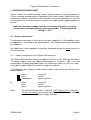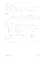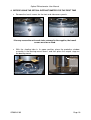
1
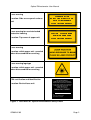
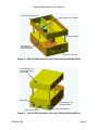
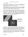
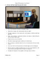
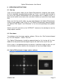
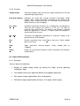
Optical Diffractometer
User Manual
GD00282 03
Manufactured by 6LUD
Optical Diffractometer User Manual
Laser warning
Location: Side access panel on base
unit
/$6(5 5$',$7,21
'2 127 9,(: ',5(&7/< :,7+
2 3 7 , & $ / ,1 6 7 5 8 0 ( 1 7 6
& / $ 6 6 0 / $ 6 ( 5 3 52 ' 8 & 7
Laser warning for non-interlocked
protective housing
&$87,21 &/$66 % /$6(5
5$',$7,21 :+(1 23(1
Location: Top cover of upper unit
&/$66 % /$6(5 352'8&7
Laser warning
Location: within upper unit - revealed
when disassembled for servicing
Laser warning logotype
Location: within upper unit - revealed
when disassembled for servicing
FDA certification and identification
Location: Back of base unit
THIS LASER PRODUCT
COMPLIES WITH THE STANDARDS
PRESCRIBED IN FDA REGULATIONS
21 CFR 1040.10 AND 1040.11 EXCEPT
FOR DEVIATIONS PURSUANT TO
LASER NOTICE No. 50
DATED JULY 26 2001
MANUFACTURED
SEPTEMBER 2003
Sira Technology Ltd
South Hill, CHISLEHURST
Kent, BR7 5EH, England
Figure 1. Facsimiles of Optical Diffractometer Safety Labels
GD00282 03
Page 2
Optical Diffractometer User Manual
Laser warning logotype label
Class 3B Laser warning label
Laser switch label
Class 1M Laser
warning label on
side access panel
Front access panel
Figure 2. Optical Diffractometer front view showing label positions
Laser warning for noninterlocked protective
housing label
Rating label
FDA certification and
identification label
Serial number label
Video connector label
Figure 3. Optical Diffractometer rear view showing label positions
GD00282 03
Page 3
Optical Diffractometer User Manual
Contents
1.
Introduction .................................................................................................................5
2.
Unpacking the Optical Diffractometer ..........................................................................7
3.
Before applying power.................................................................................................8
3.1
General safety notice ............................................................................................8
3.1.1
3.2
3.3
3.4
Power arrangement for the Optical Diffractometer....................................................... 8
Operating conditions .............................................................................................9
Electrical safety.....................................................................................................9
Laser safety ..........................................................................................................9
4.
Before using the Optical Diffractometer for the first time ...........................................10
5.
Optical Diffractometer main features .........................................................................11
6.
Operating Instructions ...............................................................................................12
6.1
6.2
6.3
Start up ...............................................................................................................12
Shut down ...........................................................................................................12
Optical Diffractometer image capture software ...................................................12
6.3.1
6.3.2
6.3.3
6.3.4
6.3.5
6.4
Summary .................................................................................................................... 13
Environment ............................................................................................................... 13
Initial display ............................................................................................................... 13
Troubleshooting.......................................................................................................... 13
Controls ...................................................................................................................... 14
Optical Diffractometer .........................................................................................14
6.4.1
6.4.2
6.4.3
6.4.4
6.4.5
6.4.6
6.4.7
6.4.8
6.4.9
Summary .................................................................................................................... 14
Using the sample stage.............................................................................................. 15
Adjusting the stops ..................................................................................................... 15
Laser diode intensity .................................................................................................. 15
Real-space image adjustment.................................................................................... 16
Diffraction image adjustment...................................................................................... 16
Using the laser cross-hair .......................................................................................... 17
Using the Optical Diffractometer ................................................................................ 17
Image calibration ........................................................................................................ 18
7.
Maintenance..............................................................................................................19
8.
General specification.................................................................................................20
Appendix A - International design standards ......................................................................21
Appendix B - Warranty .......................................................................................................22
Appendix C - Useful addresses ..........................................................................................23
GD00282 03
Page 4
Optical Diffractometer User Manual
1. INTRODUCTION
This instrument was developed by Dr W. B. Amos for the MRC Laboratory of
Molecular Biology, Cambridge, where Klug and De Rosier first introduced the
diffraction analysis of electron micrographs in the 1960s.
Sira Technology Ltd have joined forces with MRC Laboratory of Molecular Biology
to bring the instrument to the molecular biology research community. The prototype
design, proven in the MRC laboratory with thousands of hours of use by MRC
scientists, has been updated by Sira for manufacture and export.
Extensively tested by MRC scientists, this diffractometer eliminates the difficulty of
use and eye-strain of earlier diffractometers. Risk of direct user exposure to the laser
light is eliminated. The novel optical design allows the use of two high-resolution
video cameras to capture the diffraction pattern and the real-space image
simultaneously. It is possible to scan over a micrograph rapidly, using the real-time
video image, and view at the same time the corresponding diffraction pattern, and
then capture both digital images to disk. The magnification of both the real-space
and the diffraction images can be varied independently.
Real-space and
diffraction images of
a biological sample.
(Courtesy MRC Laboratory
of Molecular Biology)
To facilitate the surveying of large numbers of micrographs, particular attention has
been paid to the stage of the Optical Diffractometer, which allows translation and
rotation of the image around a fixed centre. The holder makes contact only with the
edges of the micrograph, and adjustable masking baffles do not make contact with it.
The instrument is straightforward to calibrate by scanning a reference target.
Instruments will be installed at the user’s premises by trained technicians, and
instruction provided in its operation. The Optical Diffractometer is simple to operate
and requires no special skills or technical background (except for the biological
interpretation of the images themselves).
GD00282 03
Page 5
Optical Diffractometer User Manual
It is the responsibility of the user to ensure safe operation of the unit by reading this
manual in full, following the instructions within, and taking all reasonable precautions
in its operation.
This manual is subject to change without notice.
GD00282 03
Page 6
Optical Diffractometer User Manual
2. UNPACKING THE OPTICAL DIFFRACTOMETER
Your system has been carefully tested for performance and safety. It should reach
you in perfect condition. Inspect the packaging on delivery, and if there is any
damage immediately notify your supplier and the carrier. In the event of damage all
packing must be saved for later inspection.
Remove all external packaging. The packaging will contain:
x Optical Diffractometer including:
o Main unit
o Large and small sample holders
o Sample stage
o Protective window assembly
o Two 75: video cables
o Mains Lead
x System PC including:
o Frame grabber cards, documentation and software
o Manufacturers documentation and software
o Optical Diffractometer image capture software
o PDF version of user manual
o Keyboard
o Mouse
o Mains lead
x Flat screen monitor
o Manufacturers documentation and software
o Mains lead and cables
In the event of damage to the unit, the equipment should not be used until its safe
operation has been verified by a qualified engineer. Until this verification has been
performed, the equipment should be labelled “Unsafe - Do Not Use” to inform
potential users of its status.
If for any reason the unit needs to be returned to the supplier, the original
packaging must be used.
GD00282 03
Page 7
Optical Diffractometer User Manual
3. BEFORE APPLYING POWER
Please read all the following safety notices carefully before using the equipment.
Failure to comply with precautions highlighted in the safety notices violates the safety
standards of design, manufacture and intended use of the equipment. If you are
unclear about any of the points please contact your supplier before applying power to
the unit.
Make sure the mains voltage selection on the back of the PC is set to the
correct value (see manufacturers quick setup guide). The factory default
setting is “230”.
3.1 General safety notice
The equipment described in this manual has been supplied in a safe condition (refer
to Appendix A – International Design Standards). The equipment has been designed
for indoor use.
No modification to the equipment should be attempted without the prior consent of
the manufacturer.
3.1.1 Power arrangement for the Optical Diffractometer
The Optical Diffractometer mains input power socket is an IEC 320 type connector.
The power supply inside the Optical Diffractometer is “universal”, and, it can be
connected to a (reliably grounded) 240V rms single-phase 50Hz, or 110V rms singlephase 60Hz supply, without the need to change any settings.
The following colour coding should used for power leads when connecting to the
power supplies:
brown
blue
yellow/green -
line or hot
neutral
earth or ground
or
black
white
green
line or hot
neutral
earth or ground
Note:
The Optical Diffractometer is fitted for a 5A T fuse in the live and a 5A
T fuse in the neutral at the power input socket. The 5A current rating is
suitable for the full range of supply voltages.
GD00282 03
-
Page 8
Optical Diffractometer User Manual
3.2 Operating conditions
The Optical Diffractometer has been designed for use in normal laboratory / office
conditions. No special lighting arrangements are required.
The Optical Diffractometer is not intrinsically safe, nor explosion-proof. It must not be
operated in the presence of flammable gases, fumes or chemical hazard.
3.3 Electrical safety
It is not necessary to gain access to the inside of the Optical Diffractometer during
normal operation, other than through the freely opening side and front access panels
in the base unit. Equipment repair must be performed only by qualified service
engineers. Components must not be replaced whilst the power cord (mains lead) is
connected.
3.4 Laser safety
When operated normally the Optical Diffractometer is a class 1M laser system.
There is no requirement for a designated laser safety area with restricted access.
However, during servicing the following may occur:
x When covers from the upper unit are removed, access to Class 3B laser
radiation is possible.
x When the cross-hair generator laser module is being replaced, access to
Class 2 laser radiation is possible.
Do not attempt to stare directly into the beam. Do not attempt to insert a mirror
or other reflecting device into the beam. Do not unscrew any fixed covers.
The Optical Diffractometer carries certification and warning labels as shown in
Figure 1.
Note that the green light used for the real-space image is from an LED source and is
eye-safe.
GD00282 03
Page 9
Optical Diffractometer User Manual
4. BEFORE USING THE OPTICAL DIFFRACTOMETER FOR THE FIRST TIME
x Remove the transit screws for the front and side access panels.
Side access panel
transit screw
Front access
panel transit
screw
If for any reason the unit needs to be returned to the supplier, the transit
screws must be re-fitted.
x With the shading tube in its upper position, place the protective window
assembly in the bearing mount recess, and then place the sample stage on
the bearing mount.
Shading tube
in its upper
position
Sample stage
Removable protective
window assembly
Bearing mount
GD00282 03
Page 10
Optical Diffractometer User Manual
5. OPTICAL DIFFRACTOMETER MAIN FEATURES
x Fast, easy evaluation of electron micrograph images
x High-contrast images from enclosed precision laser optics
x Compact, ergonomic, hi-tech design with small footprint, suitable for desk-top
operation
x Allows high-resolution, simultaneous display and capture of both diffraction
and real-space video images.
x Simple to set up, use and maintain
x Diffraction image magnification variable over a 6-fold range
x Does not require a darkened room for use or restricted access for laser safety
reasons
x Laser cross-hair for marking location of selected regions on the micrograph
x Service contract available providing worry free year round operation, with
annual check-up and replacement of limited life components
x Complete with computer, frame grabber and image capture software
GD00282 03
Page 11
Optical Diffractometer User Manual
6. OPERATING INSTRUCTIONS
6.1 Start up
There are three power cables for the Optical Diffractometer, computer and monitor.
All three should be connected before power up. There is an on/off switch located at
the rear of the Optical Diffractometer next to the power inlet. In addition, there is a
green on/off switch on the front of the unit which switches on and off the laser diode
only.
Make sure that the coaxial cables are connected between the Optical Diffractometer
and the frame grabber cards in the PC. The Optical Diffractometer video connectors
are labelled “Real Space” and “Diffraction” as are the corresponding frame grabber
cards.
Switch on the PC and click on the ‘DIFFRACT’ shortcut on the desktop to start the
image capture software.
6.2 Shut down
To shutdown, close the image capture software. Click on the “Start” button followed
by “Turn off Computer”. Select “Turn Off”.
The Optical Diffractometer should be powered down by first turning off the laser
diode at the front panel and then depressing the off switch at the rear of the unit.
If the system is left powered up but unused for a significant length of time, turn off
the laser diode using the switch on the front panel, to save laser diode lifetime.
6.3 Optical Diffractometer image capture software
GD00282 03
Page 12
Optical Diffractometer User Manual
6.3.1 Summary
The Optical Diffractometer software displays two live monochrome video images
simultaneously on a PC screen. One is the original real-space image of the
micrograph, the other is the reciprocal space diffraction pattern. At any time one of
these images is shown full size (i.e. at full pixel resolution), the other reduced to half
size; the user selects which is displayed as the main image. Snapshots of the main
image may be saved to disk in Tagged Image File Format (TIFF).
6.3.2 Environment
The program diffract.exe is a Visual Basic application. It runs on a PC under
Windows 98SE and above. A high-resolution screen is required, with the display set
to 1280 x 1024 pixels. Two EureCard Picolo boards must be correctly installed in the
PC for the application to run. Each board should be connected by a 75: video cable
to the appropriate monochrome video camera (image size 768 x 576 pixels).
6.3.3 Initial display
When the application is started, it should immediately begin to show live video
images from both cameras, and the status window at top right will show “Running”.
The diffraction image will initially be displayed in the left (main) area, the real-space
image in the right (reduced) area.
6.3.4 Troubleshooting
If the application does not start, and you get is an error message box, then it is likely
that either the hardware (two Picolo boards) or the software (MultiCam for Picolo
driver) is not correctly installed. In this case refer to Euresys documentation. You can
also try running the Euresys application EasyGrab.exe as a test of operation.
If the application starts, but the status window shows “Error on 1” or “Error on 2” it
indicates that there is no video signal detected by one of the boards. It is likely that
either power to the Optical Diffractometer is not turned on, or else the video cables
are disconnected. After rectifying the situation, click Run on the menu bar to start live
video display.
If the real-space image is labeled as being the diffraction image, and vice versa, then
exchange the video cable connections at the back of the PC.
GD00282 03
Page 13
Optical Diffractometer User Manual
6.3.5 Controls
Toggle images
Clicking the button swaps the camera images between the main and
reduced image display areas
Real-space display
Selecting the check box marked “Enhance Real-Space Image
Display” alters camera parameters according to the setting of the
adjacent slider / numeric entry box. This can make it easier to discern
darker features on the micrograph.
File | Save
Suspends acquisition and brings up a standard file save dialogue to
allow the main image to be saved as a TIFF file (*.tif) with any
required name and location. The default save directory, initialized
when the application is started, is c:\temp. When the dialogue is
closed, acquisition resumes.
File | Exit
Terminates the application (equivalent to using the X button at the
top right corner of the window).
Run
Restarts acquisition after using Stop or after error. Status window
goes to “Running”.
Stop
Stops acquisition, freezing displays. Status window goes to
“Stopped”.
About
Brings up a box giving software version information and company
contact details.
6.4 Optical Diffractometer
6.4.1 Summary
You can adjust the following:
x Region of sample being tested, by moving the stage, and by adjusting
rectangular stops
x Laser diode intensity (to cope with different micrograph exposures)
x Real-space image magnification, focus and aperture
x Diffraction image magnification and focus in 3 ranges (6 fold range)
GD00282 03
Page 14
Optical Diffractometer User Manual
6.4.2 Using the sample stage
Shading tube
in its lower
position
Toggle
Sample holder
Sample stage
Beam stop
There are two rectangular
sample holders designed to
accept
standard
format
micrographs. Before inserting
the sample holder under the
shading tube, move the tube to
its upper position by depressing
the toggle and sliding it up (see
section 4). The holders can be
freely moved around under the
beam. The stage rotates so that
the eye can pick out faint
features in the diffraction space
image.
6.4.3 Adjusting the stops
There are four independently adjustable beam stops on the ‘shading tube’ that can
be used to reduce the field of view of the instrument. The real-space view can be
used to see exactly what the current field of view is.
6.4.4 Laser diode intensity
The knob on the left of the upper
unit adjusts laser diode intensity
as seen in the diffraction image.
Laser diode intensity
adjustment
The internal mechanism allows
fine control, requiring 20 turns to
go from minimum to maximum.
Note that the control has no end
stop, and wraps from maximum
back to minimum.
Note also that adjusting this control has NO EFFECT on the real-space image.
GD00282 03
Page 15
Optical Diffractometer User Manual
6.4.5 Real-space image adjustment
Zoom
Focus
Aperture ring
Pull open the front access panel
to access the real-space lens.
You can adjust the focus (left
ring), magnification or ‘zoom’
(middle ring) and aperture (right
ring).
It is recommended that the
aperture is left wide open for
maximum real-space image
brightness.
Close the front access panel after adjustment to minimise stray light entering
the diffraction camera
6.4.6 Diffraction image adjustment
Lens holder
Do not touch the
beam steering
mirror controls
Diffraction camera carriage
Accessory lens carriage
Pull open the side access panel to access the diffraction image adjustments.
Each of the two carriages can be moved along the bench to change the
magnification and focus. The left carriage carries the camera. The right carriage
carries an accessory lens holder with 3 different magnification powers.
DO NOT TOUCH the beam steering mirror controls
View the diffraction image on the computer screen. Adjust the location of the left
carriage to obtain a sharp diffraction pattern.
GD00282 03
Page 16
Optical Diffractometer User Manual
Close the side access panel after adjustment to reduce the stray light reaching
the camera and maximise contrast
To change the magnification, change the lens being used on the accessory carriage
by firmly pushing or pulling the lens holder in or out of the instrument. The central
setting is empty (no magnification or reduction) which is the ‘normal’ setting. In this
setting, the location of the accessory carriage along the bench has no effect.
To increase the magnification, push the accessory lens holder in until it clicks. Then
adjust the left carriage to re-focus. The highest magnification is achieved with the
camera carriage at the far left and accessory carriage to the right.
To reduce the magnification, pull the accessory lens holder out until it clicks. Then
adjust the right carriage to re-focus. The greatest reduction is achieved with the
camera carriage almost touching the accessory carriage.
After changing the magnification, consider re-calibrating the Optical Diffractometer by
capturing an image from a test pattern (see section 6.4.9 below).
6.4.7 Using the laser cross-hair
A laser cross-hair generator is
available to enable you to
(manually) mark the edges of
the micrograph to show the
location of an area of interest.
Push the cross-hair generator to
the right until it clicks.
Laser cross-hair
generator
Sample holder
Shading tube
beam stop
The cross-hair comes on
automatically. Use a pen to
mark
the
edges
of
the
micrograph in line with the
cross-hair. This shows where
the Optical Diffractometer field
of view is centred.
6.4.8 Using the Optical Diffractometer
Use the real-space image to find areas of interest on your micrograph. Adjust the
real-space display setting in the software (see section 6.3.5) if your micrograph is
heavily exposed and the image very dark.
If necessary, use the beam stops on the ‘shading tube’ to restrict the field of view to
a small region.
GD00282 03
Page 17
Optical Diffractometer User Manual
Use the diffraction image to view and assess the diffraction pattern. If necessary,
adjust the laser intensity using the intensity knob, or the fine focus by adjusting the
camera carriage. Change the magnification up or down by following the instructions
above.
If a good image is obtained, you can save it to disk (see section 6.3.5).
Use the laser cross-hair generator to mark on your micrograph the region where the
image was captured.
6.4.9 Image calibration
If you wish to calibrate your images, you will need to view a micrograph with a test
grating of precisely known dimensions. It is good practice to capture reciprocal space
images every time you change the magnification.
GD00282 03
Page 18
Optical Diffractometer User Manual
7. MAINTENANCE
The only operational maintenance required of the user is to clean dust from the
protective window that sits in the bearing mount recess (see section 4). To remove
the protective window for cleaning, first remove the sample stage. Light
contamination of optical surfaces by dust is unavoidable in a normal laboratory and
office environments, and will not significantly affect the performance of the Optical
Diffractometer. Dust contamination may be reduced to an insignificant level by gently
blowing with a proprietary dry gas jet duster. Resist the temptation to remove dust
from an optical surface using human breath, as there is a high risk of surface
contamination. Also, do not use a laboratory air line as this will typically contain oil.
WARNING: Ensure that the unit is switched off and mains power removed before
undertaking maintenance.
WARNING: Operational maintenance does not necessitate gaining access to the
inside of the instrument other than through the front and side access
panels in the base unit. If any fixed covers are removed, the warranty is
void.
WARNING: If the cross-hair generator is removed from its mount, and the
projection head is subsequently detached from the laser module, there
will be human access to Class 2 laser radiation. A manufactures
warning label is affixed to the laser module.
WARNING: If any fixed covers in the upper unit are removed, there will be human
access to Class 3B laser radiation. A warning notice is affixed on top of
the instrument.
GD00282 03
Page 19
Optical Diffractometer User Manual
8. GENERAL SPECIFICATION
Laser safety class
670nm and 635nm, Class 1M
Dimensions
610 x 400 x 510mm (24 x 15.7 x 20.1in )
(L x W x H)
Weight
25 kg (11.4lb)
Power requirements
110V – 240 VAC, 50 – 60 Hz single-phase
Light sources
Microlens laser diode (670nm) of 8-10 mW for
diffraction image.
Light-emitting-diode source for real-space image
with peak intensity at 520nm.
Low power laser cross-hair generator (635nm) to
assist marking areas of interest.
Quoted lifetime of all sources exceed 5000 hours
continuous operation.
Dynamic range
Laser intensity variable over a 30dB range, allowing
the examination of micrographs of almost any
optical density.
Max. micrograph viewing area
20mm square. Adjustable masks allow rotation and
reduction of target area as desired.
Constant basic setting
0.1mm = 104 pixels in diffraction image (767 x 575
pixels total size). Variable within the range 0.1mm =
49 pixels to 0.1mm = 316 pixels. Easily calibrated
using reference target.
Image capture device
2 GHz PC, or better, equipped with 1280 x 1024
display and dual-input frame grabber (768 x 576
pixel). Image capture software supplied installed.
Notes:
GD00282 03
E & OE
All dimensions and weights are nominal
Sira reserves the right the change this specification without prior notice
Page 20
Optical Diffractometer User Manual
Appendix A - International Design Standards
Electromagnetic Conformity
The equipment has been designed and manufactured to comply with the following
specifications:
BS EN 61326:1998 Emissions
BS EN 61326:1998 Immunity
Electrical Safety
The equipment has been designed and manufactured to comply with the following
specification:
BS EN 61010-1
Laser Safety
The equipment conforms to the standards prescribed in regulations:
FDA 21 CFR 1040.10
FDA 21 CFR 1040.11
except for deviations pursuant to Laser Notice 50 dated July 26 2001
and
IEC 60825-1
GD00282 03
Page 21
Optical Diffractometer User Manual
Appendix B - Warranty
Sira warrants and guarantees that all new equipment and parts supplied are free
from defects of material and construction, and that all precautions which are usual
and reasonable have been taken to secure excellence of materials and
workmanship. Accordingly, Sira's liability shall be limited to replacing or repairing
without charge any material or constructional defects which become apparent within
12 months after delivery to the original purchaser.
This warranty shall not apply to any equipment which on inspection by Sira is found
to have defects resulting from accident, transportation, neglect, misuse, wear and
tear or any other cause outside its control.
The supplier of the Optical Diffractometer cannot be held responsible for any
equipment which is modified or used in a dangerous manner.
The manufacturer is unable to guarantee that the equipment is suitable for the
purchaser's applications. The way in which the equipment is used and the test
results applied is entirely a matter for the purchaser. Sira accepts no liability for
damages consequential to the use of, or defects in, its products.
GD00282 03
Page 22
Optical Diffractometer User Manual
Appendix C - Useful Addresses
Optical Diffractometer Manufacturer
Sira Technology Ltd
South Hill
Chislehurst
Kent
BR7 5EH
England
Tel:
Fax:
Website:
E-mail:
GD00282 03
+44 (0)20 8467 2636
+44 (0)20 8467 1902
http://www.sira.co.uk/
[email protected]
Page 23