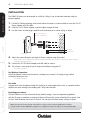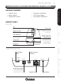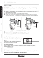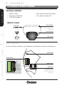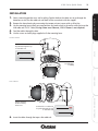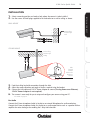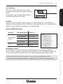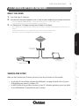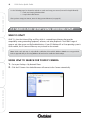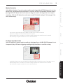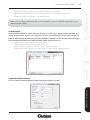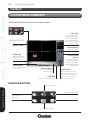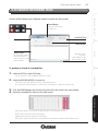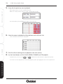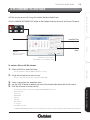
1
X100 SERIES
User Manual
2
X100 Series Quick Guide
RECORDING SOFTWARE
CONFIGURE
SETUP
INSTALL & CONNECT
QUICK GUIDE CONTENTS
INTRODUCTION.................................................................................................... 5
i Overview ............................................................................................................ 5
ii Features ............................................................................................................. 5
Standard Features across the Range ............................................................... 5
Additional Features ......................................................................................... 6
iii Minimum System Requirements ................................................................ 7
iv Notes on Installation ................................................................................... 8
INSTALL & CONNECT ......................................................................................... 9
1.1 X100C Wireless IP Cube Camera ................................................................ 9
1.2 X10⁴P Wireless Pan Tilt Zoom IP Camera ................................................ 11
1.3 X100D IP Dome Camera .............................................................................. 14
1.4 X100V Vandal Resistant IP Dome Camera ............................................... 18
1.5 X100B IP Bullet Camera .............................................................................. 22
1.6 X100T IP Body Camera ................................................................................ 25
1.7 X10⁴S Vandal Resistant IP Speed Dome .................................................. 29
1.8 X100VS Video Server (Codec) .................................................................... 32
SETUP .................................................................................................................... 35
2.1 Setting up your Network ............................................................................. 35
2.2 Search and Setup using IPWizard II ........................................................... 36
2.3 Search and Setup using Windows UPnP ................................................... 40
2.4 Setup behind a NAT Router ........................................................................ 41
2.5 Access your Camera using your Web Browser ........................................ 42
CONFIGURE .......................................................................................................... 43
3.1 Web Browser Interface ................................................................................ 43
3.2 Active X Controls .......................................................................................... 44
3.3 Main Settings Menu ..................................................................................... 47
3.4 Network Menu .............................................................................................. 48
3.5 Camera Menu ................................................................................................ 58
3.6 System Menu ................................................................................................. 62
3.7 Video Menu .................................................................................................... 66
3.8 Audio Menu ................................................................................................... 69
3.9 User Menu ...................................................................................................... 70
3.10 E-Mail Menu ................................................................................................. 71
X100 Series Quick Guide
72
74
75
76
80
84
SETUP
CONFIGURE
RECORDING SOFTWARE
RECORDING SOFTWARE ............................................................................................................. 86
- MAIN CONSOLE SETUP
4.1 Install Recording Software ................................................................................................... 86
4.2 Main Interface ......................................................................................................................... 88
4.3 Quick Start ............................................................................................................................... 90
4.4 Live Viewing Options ............................................................................................................. 96
4.5 System Setup ........................................................................................................................... 98
4.5.1 System Tab ....................................................................................................................... 98
4.5.2 Camera Tab ...................................................................................................................... 100
4.5.3 User Tab ........................................................................................................................... 102
4.5.4 Address Book Tab ............................................................................................................ 103
4.5.5 Notification Tab ................................................................................................................ 104
4.6 Schedule Setup ........................................................................................................................ 106
4.6.1 Daily Tab ........................................................................................................................... 107
4.6.2 Weekly Tab ....................................................................................................................... 107
4.6.3 Special Day Tab ................................................................................................................ 106
4.6.4 Adjusting Time Schedules ................................................................................................ 109
4.6.5 Record Setup .................................................................................................................... 110
4.7 Start & Stop Monitor ............................................................................................................. 112
4.8 E-Map ........................................................................................................................................ 114
4.9 Two Way Audio ....................................................................................................................... 115
4.10 PTZ Control ............................................................................................................................ 116
4.11 Alarm Setting ........................................................................................................................ 117
4.11.1 Setting/Adding and Event .............................................................................................. 117
4.11.2 Editing and Event ........................................................................................................... 118
4.11.3 Deleting an Event ........................................................................................................... 120
4.11.4 Event Actions .................................................................................................................. 120
4.12 Log Viewer ............................................................................................................................. 123
4.12.1 System Log Tab .............................................................................................................. 123
4.12.2 Event Log Tab ................................................................................................................. 124
4.12.3 Error Log Tab .................................................................................................................. 124
INSTALL & CONNECT
3.11 Object Detection Menu .......................................................................................................
3.12 Storage Menu .......................................................................................................................
3.13 Recording List Menu ............................................................................................................
3.14 Event Server Menu ...............................................................................................................
3.15 Event Schedule Menu ..........................................................................................................
3.16 PTZ Control ............................................................................................................................
3
RECORDING SOFTWARE
CONFIGURE
SETUP
INSTALL & CONNECT
4
X100 Series Quick Guide
- PLAYBACK
4.13 Playback Interface ................................................................................................... 126
4.14 Search Recorded Files ............................................................................................. 127
4.15 Convert to AVI Files ................................................................................................ 129
4.16 Audio Modes ............................................................................................................ 130
4.17 Playback Settings .................................................................................................... 131
4.18 Snapshot Function ................................................................................................... 132
4.19 Backup Files .............................................................................................................. 133
4.20 Split Screen Options ............................................................................................... 135
- OTHER INFORMATION
4.21 Repair Database ...................................................................................................... 138
4.22 Uninstall .................................................................................................................... 139
APPENDICES ..................................................................................................................... 140
A Connection Configuration ........................................................................................ 140
B Enabling UPnP Settings ............................................................................................ 141
C Configure Port Forwarding Manually .................................................................... 143
D DynDNS.org DDNS Service ...................................................................................... 145
E 3GPP ............................................................................................................................ 149
F PING IP Address ......................................................................................................... 150
G Troubleshooting and FAQs ....................................................................................... 151
SPECIFICATIONS ............................................................................................................... 156
X100C Wireless IP Cube Camera .................................................................................... 156
X104P Wireless Pan Tilt Zoom IP Camera ..................................................................... 158
X100D IP Dome Camera .................................................................................................. 160
X100V Vandal Resistant IP Dome Camera .................................................................... 18
X100B IP Bullet Camera ................................................................................................... 22
X100T IP Body Camera ..................................................................................................... 25
X104S Vandal Resistant IP Speed Dome ...................................................................... 29
X100VS Video Server (Codec) ....................................................................................... 32
X100 Series Quick Guide
5
i OVERVIEW
ii FEATURES
STANDARD FEATURES ACROSS THE X100 IP CAMERA RANGE
INSTALL & CONNECT
This user guide explains how to operate your camera from a computer. Please ensure you read this
manual before attempting to operate the device.
• Easy ‘Plug and Play’ installation and configuration using the Setup Wizard
• 1.3 Megapixel High Definition images up to 1280x1024 resolution, 3x the resolution of standard
CCTV cameras
• IEEE 802.3af Power over Ethernet (except X100C and X104P)
• Up to 30 fps in VGA mode, 15 fps in Megapixel mode
• Digital Zoom for detailed viewing
SETUP
• Choice of compressions and multiple streams for optimum performance in any environment
• Remote Viewing from anywhere in the world using any standard PC or Mac web browser
• Supports 3G Mobile Viewing on all popular mobile phones, including Android, iPhone, Symbian
(Nokia) & Windows Mobile
• Intelligent Motion Detection with Automatic Email Alerts & Local Alarm* Notifications when
motion is detected
• Two-way audio for remote communication with people near the camera*
• Supports DDNS (Dynamic Domain Name System)
• Supplied with Free Multi-channel Management and Recording software for up to 64 IP Cameras
*Speakers will need to be plugged in to the camera for this function
CONFIGURE
• Alarm Input and Output
RECORDING SOFTWARE
6
X100 Series Quick Guide
RECORDING SOFTWARE
CONFIGURE
SETUP
INSTALL & CONNECT
ADDITIONAL FEATURES
X100C WIRELESS IP CUBE CAMERA
• White LEDs for 10m Night Vision
• 4.0mm Lens for 50° viewing angle
• SD Card Recording
• Designed for Wall, Ceiling or Desk
mounting
• Suitable for indoor use only
X104P WIRELESS PAN TILT ZOOM
IP CAMERA
• White LEDs for 10m Night Vision
• 4.0mm lens for 50° viewing angle
• Motorised Pan (355°) and Tilt (100°)
• Designed for Wall, Ceiling or Desk
mounting
• Suitable for indoor use only
X100D IP DOME CAMERA
• 4.0mm Lens for 50° viewing angle
• Optional lenses available for 35°, 43°, 85°,
or 135° viewing
• Power Over Ethernet
• Designed for Wall or Ceiling Mounting
• Suitable for indoor use only
X100V VANDAL RESISTANT IP DOME
CAMERA
• Vandal Resistant
• IR LEDs for 30m Night Vision
• 2.7 to 9.0mm Lens for 20 to 80° viewing
angle
• Power Over Ethernet
• Designed for Wall or Ceiling Mounting
• Suitable for indoor or outdoor use
X100B IP BULLET CAMERA
• IR LEDs for 20m Night Vision
• 4.0mm Lens for 50° viewing angle
• Power Over Ethernet
• Designed for Wall or Ceiling Mounting
• Suitable for indoor or outdoor use
X100T IP BODY CAMERA
• C/CS Mount Lens with Auto Iris Support
• Supplied with a 4.0mm lens as standard
for 50° viewing angle
• Optional lenses available for fixed or
varifocal viewing angles
• Power Over Ethernet
• Designed for Wall or Ceiling Mount
• Optional Accessories available for external
mounting
• Suitable for indoor use as supplied
X104S VANDAL RESISTANT IP SPEED
DOME
• Vandal Resistant
• 4.0mm lens for 50° viewing angle
• Motorised Pan (355°) and Tilt (100°)
• Power Over Ethernet
• Designed for Ceiling Mount
• Optional Wall Mount available
• Suitable for indoor or outdoor use
X100VS VIDEO SERVER
• Single Input Video Server
• Converts any type of analogue CCTV
camera into IP
• Power Over Ethernet
• SD Card Recording
• Audio Input
• Suitable for indoor use only
X100 Series Quick Guide
7
iii MINIMUM SYSTEM REQUIREMENTS
The following are the minimum system requirements for the X100 Series IP Camera Range:
Wired Models
Wireless Model (X100C, X104P)
Network Interface:
10/100MBase-TX Ethernet
10/100MBase-TX Ethernet
802.11b/g or n WLAN
Browser:
Internet Explorer 6.0, Safari 5.0, FireFox 3.5 or later
System Hardware
CPU:
Pentium 4, 2.0 GHz or higher
Memory:
512 MB or above
VGA Card Resolution:
1024 x 768 or above
Sound Card:
for 2 Way Audio function (optional depending on model)
CPU:
Display:
120
120 to 360
360 to 540
540 to 960
960+
VGA
30
30 to 90
90 to 135
135 to 240
240+
SXGA
8
8 to 23
23 to 34
34 to 60
60+
Intel P4
2.4GHz
Intel P4
3.2GHz
Intel
Pentium D
950
3.4GHz
Intel Core 2
Duo
E8600
3.3GHz
Intel Core
2 Quad
Q9650
3.0GHz
512 MB
1 GB
1024 x 678 resolution or above
DirectX 9.0c or above
Intel 945G/965G or above
Windows XP,
Windows Vista*
Windows 7
OS:
Hard Drive:
Chipset:
Minimum 60GB recommended
For Multi-channel recording, use 7200rpm or higher speed HDD
100 MBps
Intel 945 or Intel 965 or above
*When using Vista it is recommended that extra memory is installed
1 GBps
RECORDING SOFTWARE
Ethernet:
2 GB
CONFIGURE
RAM:
QVGA
SETUP
System Requirements for Viewing and Recording Software
Estimated Total
Display and
Recording FPS:
INSTALL & CONNECT
Network Environment
X100 Series Quick Guide
8
RECORDING SOFTWARE
CONFIGURE
SETUP
INSTALL & CONNECT
iv NOTES ON INSTALLATION
•
Please unpack all boxes carefully and identify that all the parts are present.
•
Do not aim the camera at the sun or similar intense light.
•
Treat the camera with care.
•
Do not open the camera to make internal adjustments unless instructed to do so in this manual.
•
Avoid using the camera in very hot or very cold temperatures or in areas of high humidity (unless the
camera is designed for outdoor use).
•
Ensure the camera is well ventilated. It should not be placed near heated devices such as radiators or
heat elements.
•
The camera should be installed on a firm and solid surface. Wall or Ceiling mounting the camera should
be done with care to ensure the camera weight can be supported safely.
•
Do not cut the camera cables, this will void the warranty.
•
Only use the supplied power adaptor. Using a different adaptor may cause the camera to malfunction,
heat up or catch fire. Any damage cause to the camera by using the incorrect power adaptor will void
the warranty.
•
Do not tamper or open the power adaptor supplied.
X100 Series Quick Guide
9
1.1 X100C WIRELESS IP CUBE CAMERA
PACKAGE CONTENTS
INSTALL & CONNECT
•
•
•
•
•
•
X100C IP Camera
Wireless Antenna
Camera Bracket
Fixing Screws & Wall Plugs
12V DC Power Adaptor
User’s Manual & Software CD
IDENTIFY PARTS
FRONT VIEW
SD Card Slot
Insert SD Card for on
board recording
Night Vision LEDs
Network Type LED
(Green/Orange)
CONNECTIONS
Microphone
CONFIGURE
Green LED indicates
Wired connection is
active. Orange LED
indicates Wireless
connection is active.
SETUP
Wireless Antenna
Connector
Focus Ring
Reset Button
Ensure only the 12V DC
Power Adaptor supplied
with the camera is used.
Network Port
Audio Output Socket
RECORDING SOFTWARE
12V DC Power Socket
10
X100 Series Quick Guide
INSTALL & CONNECT
INSTALLATION
The X100C IP Camera can be mounted on a Wall or Ceiling. It can also be desk mounted using the
bracket supplied.
1.
2.
3.
For Wall or Ceiling mounting, make a hole where the camera is to be installed to insert the 12V DC
Power Adaptor and LAN cable.
Feed the 12V DC Power Adaptor, and LAN cables through the hole.
Use the screws and wall plugs supplied to fix the bracket on a wall or ceiling as shown.
SETUP
Turn anti-clockwise to
loosen for adjustment
To Power
To Network
Focus Ring
4.
5.
6.
Adjust the camera direction and angle of view as required using the bracket.
- Make any lens (focus) adjustments using the manual Focus Ring after you have connected the camera and have
setup live viewing via your PC.
Connect the 12V DC Power Adaptor and LAN cable to camera.
The camera is now ready for you to setup and configure using your PC.
CONFIGURE
- See SETUP on page 35.
For Wireless Connection
Attach the Wireless Antenna to the camera. Configure your camera’s IP settings using a Wired
connection before you start.
- See SETUP on page 35.
RECORDING SOFTWARE
For Audio
Connect the 3.5mm microphone Audio Out Socket to an audio output device such as a speaker with an
amplifier for voice alerting or for enabling the 2 Way Audio function.
Resetting your camera
The Reset Button is used to restore the factory default settings. If you are experiencing problems
with the IP camera, sometimes restarting the device will make the system revert back to a normal state.
To reset, hold the button for at least 5 seconds. The camera will restore factory settings & reboot.
Note: Restoring the factory default setting will lose all the previous settings including the IP address.
You will need to run the IPWizard II program to re-configure the camera to enable it to work properly again.
X100 Series Quick Guide
11
1.2 X10⁴P WIRELESS PAN TILT ZOOM IP CAMERA
PACKAGE CONTENTS
• Fixing Screws & Wall Plugs
• 12V DC Power Adaptor
• User’s Manual & Software CD
IDENTIFY PARTS
INSTALL & CONNECT
• X104P IP Camera
• Wireless Antenna
• L-Bracket with 2x Screws
FRONT VIEW
Lens
Camera Body
Focus Ring
Night Vision LEDs
Lens Mechanism
Network Type LEDs
(Green/Orange)
The Lens Mechanism can tilt
(up & down) 100°.
Green LED indicates
Wired connection is
active. Orange LED
indicates Wireless
connection is active.
Camera Base
Microphone
CONFIGURE
CONNECTIONS ON BASE SIDE
Audio Output
Socket
AUDIO
OUT
SETUP
The body of the
camera can pan (left
to right) 355°.
12V DC
Wireless Antenna
Connector
LAN
RESET
Ensure only the 12V DC
Power Adaptor supplied
with the camera is used.
Network Port
Reset Button
RECORDING SOFTWARE
12V DC Power Socket
12
X100 Series Quick Guide
The X104P IP Camera can be mounted on a Wall or Ceiling using the L-Bracket provided. It is designed
for internal use only. It can also be desk mounted as supplied.
1.
2.
3.
For Wall or Ceiling mounting, make a hole where the camera is to be installed to insert the 12V DC
Power Adaptor and LAN cable.
Feed the 12V DC Power Adaptor and LAN cables through the hole.
Use the screws and wall plugs supplied to fix the bracket to the camera, then to the ceiling as
shown. For wall mounting, fix the bracket to the wall before mounting the camera to the bracket.
SETUP
INSTALL & CONNECT
INSTALLATION
Power &
LAN cable
CEILING MOUNT
RECORDING SOFTWARE
CONFIGURE
4.
5.
Power &
LAN cable
WALL MOUNT
Connect the 12V DC Power Adaptor and LAN cable to camera.
The camera is now ready for you to setup and configure using your PC.
- See SETUP on page 35.
Lens Adjustment
Make any lens (focus) adjustments after you have
connected the camera and have setup live viewing via
your PC.
To adjust the lens, open the Dome Cover by turning it
anti-clockwise and rotate the Focus Ring.
Focus Ring
For Wireless Connection
Attach the Wireless Antenna to the camera. Configure your camera’s IP settings using a Wired
connection before you start.
- See SETUP on page 35.
For Audio
Connect the 3.5mm microphone Audio Out Socket to an audio output device such as a speaker with an
amplifier for voice alerting or for enabling the 2 Way Audio function.
X100 Series Quick Guide
13
Note: Restoring the factory default setting will lose all the previous settings including the IP address.
You will need to run the IPWizard II program to re-configure the camera to enable it to work properly again.
INSTALL & CONNECT
Resetting your camera
The Reset Button is used to restore the factory default settings. If you are experiencing problems
with the IP camera, sometimes restarting the device will make the system revert back to a normal state.
To reset, hold the button for at least 5 seconds. The camera will restore factory settings & reboot.
SETUP
CONFIGURE
RECORDING SOFTWARE
14
X100 Series Quick Guide
1.3 X100D IP DOME CAMERA
INSTALL & CONNECT
PACKAGE CONTENTS
• X100D IP Camera
• Fixing Screws & Wall Plugs
• 12V DC Power Adaptor
• Power Cable with terminal connections
• User’s Manual & Software CD
IDENTIFY PARTS
Dome Base
Turn anti-clockwise
to remove
Side Cable Exit
Remove when inserting
cables through the side
of the dome
SETUP
Dome Housing
Dome Cover
INTERNAL CONNECTIONS
CONFIGURE
To access the internal connections, turn the dome base anti-clockwise to uncover the dome housing.
Reset Button
RECORDING SOFTWARE
Terminal Block
VCC12
GND
DIGITAL_IN
ALARM_OUT
AUDIO_IN
AUDIO_OUT
AUDIO_GND
Network Port
Status LEDs
Green LED indicates
connection is active.
Orange LED indicates
power is ON.
X100 Series Quick Guide
15
INSTALLATION
2.
3.
4.
5.
Select a mounting position on a wall or ceiling. Rotate the dome housing anti-clockwise to remove
the camera from the mounting base.
Use the mounting base to mark up screw positions and make a hole in the wall or ceiling to insert the
LAN cable and 12V DC Cable (if using Power over Ethernet, 12V DC Power is not required).
Feed the cables through the hole.
Use the screws and wall plugs supplied to fix the mounting base.
Insert the cables through the side cable exit or from the rear of the camera.
INSTALL & CONNECT
1.
CEILING MOUNT
Holes for
fixing base to
wall or ceiling
Power Cable To Power Adaptor
SETUP
Push cables through
the side cable exit
To Network
CONFIGURE
WALL MOUNT
Power Cable To Power Adaptor
To Network
Holes for
fixing base to
wall or ceiling
RECORDING SOFTWARE
Push cables through
the side cable exit
16
6.
X100 Series Quick Guide
Adjust the camera direction and angle of view as required using the camera bracket inside.
INSTALL & CONNECT
- Make any lens (focus) adjustments using the manual Focus Ring after you have connected the camera and have
setup live viewing via your PC.
CAMERA DIRECTION ADJUSTMENT
Camera bracket
For Horizontal
Adjustment
Camera’s
Tilt bracket
For Vertical
Angle
Adjustment
SETUP
Camera’s
Board hinge
For Horizontal
(Left/Right) Board
Adjustment
Focus Ring
7.
Connect the Power Cable to the correct terminals; attach Positive (+) to VCC12 and Negative (-) to
GND as shown (if using PoE this step is not required):
CONFIGURE
+
Power Adaptor
(to Mains Power)
Power Cable
-
VCC12
GND
DIGITAL_IN
ALARM_OUT
AUDIO_IN
AUDIO_OUT
AUDIO_GND
Note: Incorrect wiring may cause damage to the camera.
RECORDING SOFTWARE
Please ensure + and - terminal connections are fitted correctly.
8. Connect the LAN cable to the Network Socket and the 12V DC Power Adaptor to the Power Cable.
9. Re-attached the dome housing to the dome base.
10. The camera is now ready for you to setup and configure using your PC.
- See SETUP on page 35.
Using an Optional Lens
The X100D camera is supplied with a 4.0mm board lens for 50° viewing angle. The lens can be manually
replaced with an Xvision Megapixel Board Lens to achieve a different viewing angle. Any lens change
should be made after you have connected the camera and have set up live viewing via your PC so that
the focus can be set correctly.
X100 Series Quick Guide
17
Place spring on
new lens before
screwing back on
to board mount
For Audio
Connect an external Microphone for monitoring audio. Connect an audio output device such as a
speaker with an amplifier for voice alerting or for enabling the 2 Way Audio function.
See table below for details on connection.
SETUP
Note: The following Xvision Megapixel lenses are compatible with the X100D IP camera:
• XL010P-PRO (1.55mm Fixed Iris Megapixel Lens, for 135° viewing angle)
• XL035P-PRO (3.5mm Fixed Iris Megapixel Lens, for 85° viewing angle)
• XL060P-PRO (6.0mm Fixed Iris Megapixel Lens, for 43° viewing angle)
• XL080P-PRO (8.0mm Fixed Iris Megapixel Lens, for 35° viewing angle)
INSTALL & CONNECT
To replace the lens:
1. Open the dome cover and carefully turn the lens to unscrew it from the board mount.
2. Once removed, slide off the small spring around the lens and place this onto the new lens.
3. Screw the new lens onto the board mount and set the required focus by turning the lens.
4. Replace the dome cover once all adjustments have been made.
Audio and Alarm Connections
POWER
ALARM SENSOR
AUDIO
Terminal Name
Connect to:
VCC12
Positive (+) Power Cable
GND
Negative (-) Power Cable
DIGITAL_IN
Alarm Sensor Input
ALARM_OUT
Alarm Output
AUDIO_IN
External Microphone / Audio Input
AUDIO_OUT
External Speaker / Audio Out
AUDIO_GND
Audio Ground
Note: Restoring the factory default setting will lose all the previous settings including the IP address.
You will need to run the IPWizard II program to re-configure the camera to enable it to work properly again.
RECORDING SOFTWARE
Resetting your camera
The Reset Button is used to restore the factory default settings. If you are experiencing problems
with the IP camera, sometimes restarting the device will make the system revert back to a normal state.
To reset, hold the button for at least 5 seconds. The camera will restore factory settings & reboot.
CONFIGURE
Grouping
X100 Series Quick Guide
18
1.4 X100V VANDAL RESISTANT IP DOME CAMERA
INSTALL & CONNECT
PACKAGE CONTENTS
•
•
•
•
X100V IP Camera
Fixing Screws
Allen Key
12V DC Power Adaptor
•
•
•
•
Power Cable with terminal connections
Side Exit Fitting
Stopper
User’s Manual & Software CD
IDENTIFY PARTS
Top Cable Exit
SETUP
Tamper Resistant
Screw Fittings
Optional Side Cable Exit
Supplied with Side Exit
Fitting and Stopper (to block
off unused cable exit)
Dome Housing
Stopper
Dome Cover
Side Exit
Fitting
INTERNAL CONNECTIONS
CONFIGURE
To access the internal connections, use the Allen Key to open the screws and uncover the dome housing.
Factory Default
Reset Button
RECORDING SOFTWARE
Terminal Block
VCC12
GND
DIGITAL_IN
ALARM_OUT
AUDIO_IN
AUDIO_OUT
AUDIO_GND
Network Port
Status LEDs
Green LED indicates
Wired connection is
active. Orange LED
indicates power is ON.
X100 Series Quick Guide
19
INSTALLATION
2.
3.
4.
5.
Select a mounting position on a wall or ceiling. Decide whether the cables are to go through the
dome base or via the side cable exit and block off the unused exit with the stopper.
Remove the dome housing by unscrewing the tamper resistant screws with an Allen Key.
Use the mounting base to mark up screw positions and make a hole in the wall or ceiling to insert the
LAN cable and 12V DC Cable (if using Power over Ethernet, 12V DC Power is not required).
Feed the cables through the hole.
Use the screws and wall plugs supplied to fix the mounting base.
INSTALL & CONNECT
1.
CEILING MOUNT
Position hole so cables can
be pushed through the top
or side cable exit
SETUP
Power Cable To Power Adaptor
To Network
Fixing Screws
for fixing base
to ceiling
CONFIGURE
WALL MOUNT
Position hole so cables can
be pushed through the top
or side cable exit
Power Cable To Power Adaptor
To Network
6.
Insert the cables through the top or side cable exit.
RECORDING SOFTWARE
Tamper Resistant
Screws for fixing
dome cover
20
INSTALL & CONNECT
7.
X100 Series Quick Guide
Adjust the camera direction and angle of view as required using the camera bracket inside.
- Make any lens (Zoom/Focus) adjustments after you have connected the camera & have setup live viewing via your PC.
- Make the Zoom Adjustment by rotating the screw anticlockwise for NEAR adjustment and clockwise for FAR
adjustment until you get the desired view. Next make the Focal Adjustment by rotating the screw anti-clockwise
for TELE adjustment and Clockwise for WIDE adjustment until you get the desired view.
- After adjustment, tighten both screws to set the Zoom and Focus Rings.
CAMERA DIRECTION ADJUSTMENT
SETUP
Camera bracket
For Horizontal
Adjustment
Camera’s
Tilt bracket
For Vertical
Angle
Adjustment
CONFIGURE
Camera’s
Board hinge
For Horizontal
(Left/Right) Board
Adjustment
LENS ADJUSTMENT
Zoom
Adjustment
Screw
RECORDING SOFTWARE
WIDE ~ TELE
Focus
Adjustment
Screw
Zoom and
Focus Rings
NEAR ~ FAR
X100 Series Quick Guide
8.
21
Connect the 12V DC Power Adaptor to the Power Cable and attach the positive (+) to VCC12 and
the negative (-) to GND as shown (if using POE this step is not required):
Power Adaptor
(to Mains Power)
-
Power Cable
VCC12
GND
DIGITAL_IN
ALARM_OUT
AUDIO_IN
AUDIO_OUT
AUDIO_GND
Note: Incorrect wiring may cause damage to the camera.
INSTALL & CONNECT
+
Please ensure + and - terminal connections are fitted correctly.
9. Connect the LAN cable to the Network Socket.
10. Re-attach the dome housing to the dome base.
11. The camera is now ready for you to setup and configure your camera using your PC.
- See SETUP on page 35.
SETUP
For Audio
Connect an external Microphone for monitoring audio. Connect an audio output device such as a
speaker with an amplifier for voice alerting or for enabling the 2 Way Audio function.
See table below for details on connection.
Audio and Alarm Connections
Grouping
ALARM SENSOR
AUDIO
Connect to:
VCC12
Positive (+) Power Cable
GND
Negative (-) Power Cable
DIGITAL_IN
Alarm Sensor Input
ALARM_OUT
Alarm Output
AUDIO_IN
External Microphone / Audio Input
AUDIO_OUT
External Speaker / Audio Out
AUDIO_GND
Audio Ground
Note: Restoring the factory default setting will lose all the previous settings including the IP address.
You will need to run the IPWizard II program to re-configure the camera to enable it to work properly again.
RECORDING SOFTWARE
Resetting your camera
The Reset Button is used to restore the factory default settings. If you are experiencing problems
with the IP camera, sometimes restarting the device will make the system revert back to a normal state.
To reset, hold the button for at least 5 seconds. The camera will restore factory settings & reboot.
CONFIGURE
POWER
Terminal Name
X100 Series Quick Guide
22
1.5 X100B IP BULLET CAMERA
INSTALL & CONNECT
PACKAGE CONTENTS
•
•
•
•
•
X100B IP Camera with Sun/Rain Shield
Camera Bracket
Fixing Screws & Wall Plugs
12V DC Power Adaptor
User’s Manual & Software CD
IDENTIFY PARTS
SIDE VIEW
Sun/Rain Shield
SETUP
Trailing Lead
Bracket
CONFIGURE
CONNECTIONS ON TRAILING LEAD
Alarm I/O connections
Microphone In Socket
Audio Output Socket
RECORDING SOFTWARE
12V DC Power Socket
Ensure only the 12V DC Power
Adaptor supplied with the
camera is used.
Network Port
(with Status LEDs)
Green LED indicates Wired
connection is active. Orange
LED indicates power is ON.
Reset Button
X100 Series Quick Guide
23
INSTALLATION
Select a mounting position and make a hole where the camera is to be installed
Use the screws and wall plugs supplied to fix the bracket on a wall or ceiling as shown.
WALL MOUNT
Feed trailing
lead through
wall
SETUP
CEILING MOUNT
Feed trailing
lead through
ceiling
- See SETUP on page 35.
For Audio
Connect the 3.5mm microphone Audio In Socket to an external Microphone for audio monitoring.
Connect the 3.5mm microphone Audio Out Socket to an audio output device such as a speaker with an
amplifier for voice alerting or for enabling the 2 Way Audio function.
RECORDING SOFTWARE
6.
Feed the trailing lead with connections through the hole.
Adjust the camera direction and angle of view as required using the bracket.
Connect the LAN cable and 12V DC Power Adaptor to camera (if using Power over Ethernet,
12V DC Power Adaptor is not required).
The camera is now ready for you to setup and configure your camera using your PC.
CONFIGURE
Slide
forward
sun/rain
shield to fix
bracket to
camera
3.
4.
5.
INSTALL & CONNECT
1.
2.
24
X100 Series Quick Guide
SETUP
INSTALL & CONNECT
Alarm and RS485 Connections
Grouping
ALARM SENSOR
(Optional)
RS485
Cable Name (Colour)
Connect to:
DI (Green/White)
Alarm Sensor Input
DO (Orange/White)
Alarm Output
12V DC (Brown/White)
Alarm Output Power (12V DC 50mA Max)
GND (Blue/White)
Alarm Sensor Ground
RS485 + (Purple/White)
Not used
RS485 - (Grey)
Not used
Resetting your camera
The Reset Button is used to restore the factory default settings. If you are experiencing problems
with the IP camera, sometimes restarting the device will make the system revert back to a normal state.
To reset, hold the button for at least 5 seconds. The camera will restore factory settings & reboot.
Note: Restoring the factory default setting will lose all the previous settings including the IP address.
RECORDING SOFTWARE
CONFIGURE
You will need to run the IPWizard II program to re-configure the camera to enable it to work properly again.
X100 Series Quick Guide
25
1.6 X100T IP BODY CAMERA
PACKAGE CONTENTS
X100T IP Camera with Lens
Camera Mount with 2x screws
Camera Bracket
Fixing Screws & Wall Plugs
• CS Mount Lens Adaptor
• 12V DC Power Adaptor
• User’s Manual & Software CD
IDENTIFY PARTS
INSTALL & CONNECT
•
•
•
•
SIDE VIEW
Lens
SETUP
Auto Iris Lens
Connection
Focus Ring
Microphone
CONNECTIONS ON REAR
Alarm I/O
connections
AUDIO
OUT
DI/DO
12V DC
12V DC Power Socket
Ensure only the 12V DC
Power Adaptor supplied
with the camera is used.
LAN
RST
Network Port
(with Network Type LEDs)
BRACKET MOUNT
Attach the Camera Mount to the top or bottom of the
camera and secure the bracket as shown.
Reset Button
RECORDING SOFTWARE
Green LED indicates Wired connection is
active. Orange LED indicates power is ON.
CONFIGURE
Audio Output
Socket
123456
26
X100 Series Quick Guide
INSTALL & CONNECT
INSTALLATION
1.
2.
3.
Select a mounting position on a wall or ceiling. Make a hole where the camera is to be installed to
insert the LAN cable and 12V DC Cable (if using Power over Ethernet, 12V DC Power is not
required).
Feed the cables through the hole.
Use the screws and wall plugs supplied to fix the bracket on a wall or ceiling as shown.
WALL MOUNT
SETUP
To Power
To Network
Focus Ring
CONFIGURE
CEILING MOUNT
To Network
RECORDING SOFTWARE
To Power
Focus Ring
4.
Adjust the camera direction and angle of view as required using the bracket.
- Make any lens (focus) adjustments using the manual Focus Ring after you have connected the camera and have
setup live viewing via your PC.
X100 Series Quick Guide
5.
6.
27
Connect the LAN cable and 12V DC Power Adaptor to camera.
The camera is now ready for you to setup and configure your camera using your PC.
Using an Optional Lens
The X100T camera is supplied with a 4.0mm fixed lens for 50° viewing angle. The lens can be manually
replaced with an Xvision Megapixel Varifocal or Fixed Lens to achieve a different viewing angle. Any
lens change should be made after you have connected the camera and have set up live viewing via your
PC so that the focus can be set correctly.
INSTALL & CONNECT
- See SETUP on page 35.
To replace the lens:
1. Carefully turn the lens to unscrew it from the camera body.
2. Screw the new lens onto the camera and set the required focus by turning the lens focus ring.
When all adjustments have been made, tighten any lens screws to ensure the zoom and focus are set.
SETUP
3.
- If you are replacing the lens with a VARIFOCAL lens, the zoom and focus should be adjusted using the separate
zoom and focus rings.
- If you are replacing the lens with a AUTO IRIS lens, ensure the Auto Iris Lens cable is connected to the
corresponding connection on the camera’s side.
REPLACING THE LENS
Ensure the Auto Iris cable
is connected here
RECORDING SOFTWARE
Note: The following Xvision Megapixel lenses are compatible with the X100T IP camera:
• XL010M-PRO (1.55mm Fixed Iris Megapixel Lens, for 135° viewing angle)
• XL040M-PRO (4.0mm Fixed Iris Megapixel Lens, for 64° viewing angle)
• XL0550M-PRO (5.0 to 50.0mm Manual Iris Varifocal Megapixel Lens, for 6 to 49° viewing angle)
• XL0409A-PRO (4.0 to 9.0mm Auto Iris Varifocal Megapixel Lens, for 30 to 64° viewing angle)
• XL4510A-PRO (4.5 to 10.0mm Auto Iris Varifocal Megapixel Lens, for 28 to 57° viewing angle)
• XL0550A-PRO (5.0 to 50.0mm Auto Iris Varifocal Megapixel Lens, for 6 to 49° viewing angle)
• XL1040A-PRO (10.0 to 40.0mm Auto Iris Varifocal Megapixel Lens, for 8 to 28° viewing angle)
CONFIGURE
AUTO IRIS LENS CONNECTION
INSTALL & CONNECT
28
X100 Series Quick Guide
For Audio
Connect the 3.5mm microphone Audio Out Socket to an audio output device such as a speaker with an
amplifier for voice alerting or for enabling the 2 Way Audio function.
Alarm and RS485 Connections
Grouping
ALARM SENSOR
(Optional)
SETUP
RS485
Pin
Connect to:
1
12V DC Power (60mA Max)
2
Alarm Sensor Input
3
GND
4
Alarm Output
5
RS485 + (Not used)
6
RS485 - (Not used)
Resetting your camera
The Reset Button is used to restore the factory default settings. If you are experiencing problems
with the IP camera, sometimes restarting the device will make the system revert back to a normal state.
To reset, hold the button for at least 5 seconds. The camera will restore factory settings & reboot.
Note: Restoring the factory default setting will lose all the previous settings including the IP address.
RECORDING SOFTWARE
CONFIGURE
You will need to run the IPWizard II program to re-configure the camera to enable it to work properly again.
X100 Series Quick Guide
29
1.7 X10⁴S VANDAL RESISTANT IP SPEED DOME
PACKAGE CONTENTS
• Allen Key
• 12V DC Power Adaptor
• User’s Manual & Software CD
IDENTIFY PARTS
SIDE VIEW
INSTALL & CONNECT
• X104S IP Camera
• Ceiling Mount with 4x Screws
• Fixing Screws & Wall Plugs
Ceiling Mount
Fixing Slot for
mounting camera
Trailing Lead
Note: An optional Wall
mount bracket is available
SETUP
Speed Dome Housing
Speed Dome Cover
for mounting the camera
against a wall.
CONNECTIONS ON TRAILING LEAD
CONFIGURE
Alarm I/O connections
Microphone In Socket
Audio Output Socket
12V DC Power Socket
Network Port
(with Status LEDs)
Green LED indicates Wired
connection is active. Orange
LED indicates power is ON.
Reset Button
RECORDING SOFTWARE
Ensure only the 12V DC Power
Adaptor supplied with the
camera is used.
30
X100 Series Quick Guide
SETUP
INSTALL & CONNECT
INSTALLATION
1.
2.
Make a hole in the ceiling where the camera is to be installed.
Use the screws and wall plugs supplied to fix the bracket on the ceiling.
Hole to feed
trailing lead
through
the ceiling
3.
Feed the trailing lead through the Ceiling Mount and fix the camera to the bracket as shown:
Screw Dome Housing to
Ceiling Mount using the
Allen Key provided
RECORDING SOFTWARE
CONFIGURE
4.
5.
Connect the LAN cable and 12V DC Power Adaptor to camera (if using Power over Ethernet,
12V DC Power Adaptor is not required).
The camera is now ready for you to setup and configure your camera using your PC.
- See SETUP on page 35.
Fitting the optional Wall Bracket
1. Make a hole in the wall where the camera is to be installed and use the screws and wall plugs
supplied to fix the bracket to the surface.
2. Feed the trailing lead through the Wall Mount and fix the camera to the bracket as shown, then
continue to wire the camera as described above.
Screw Dome Housing to
Ceiling Mount using the
Allen Key provided
Hole to feed
trailing lead
through
the wall
X100 Series Quick Guide
31
4 CAMERA INSTALLATION
Focus Ring
For Audio
Connect the 3.5mm microphone Audio In Socket to an external Microphone for audio monitoring.
Connect the 3.5mm microphone Audio Out Socket to an audio output device such as a speaker with an
amplifier for voice alerting or for enabling the 2 Way Audio function.
INSTALL & CONNECT
Lens Adjustment
Make any lens (focus) adjustments after you have
connected the camera and have setup live viewing via
your PC.
To adjust the lens, open the Dome Cover by turning it
anti-clockwise and rotate the Focus Ring.
Alarm and RS485 Connections
ALARM SENSOR
(Optional)
RS485
Cable Name (Colour) Connect to:
DI (Green/White)
Alarm Sensor Input
DO (Orange/White)
Alarm Output
12V DC (Brown/White)
Alarm Output Power
(12V DC 50mA Max)
GND (Blue/White)
Alarm Sensor Ground
RS485 + (Purple/White)
Not Used
RS485 - (Grey)
Not Used
CONFIGURE
Resetting your camera
The Reset Button is used to restore the factory default settings. If you are experiencing problems
with the IP camera, sometimes restarting the device will make the system revert back to a normal state.
To reset, hold the button for at least 5 seconds. The camera will restore factory settings & reboot.
SETUP
Grouping
Note: Restoring the factory default setting will lose all the previous settings including the IP address.
You will need to run the IPWizard II program to re-configure the camera to enable it to work properly again.
RECORDING SOFTWARE
32
X100 Series Quick Guide
1.8 X100VS VIDEO SERVER (CODEC)
INSTALL & CONNECT
PACKAGE CONTENTS
• Audio/Video Output Cable
• Power Cable for External Camera
• User’s Manual & Software CD
• X100VS Video Server
• 12V DC Power Adaptor
• User’s Manual & Software CD
IDENTIFY PARTS
FRONT VIEW
Network Port
12V DC Out Power
Socket
Alarm I/O
connections
SETUP
12V DC
OUT
LAN
DI/DO/ RS485
VIDEO IN
Power Cable for External Camera
BNC Video Input
(optional) Used to power one camera.
12V DC 400mA Max.
CONFIGURE
REAR VIEW
Status LED
Reset Button
Green LED indicates Wired connection
is active. The LED will flash when a
user accesses the unit.
12V DC
IN
RECORDING SOFTWARE
AUDIO
IN
Microphone In
Socket
microSD
STATUS
Micro SD
Memory
Card Slot
Insert SD Card for
on board recording
RESET
Audio/Video
Output Socket
AUDIO/VIDEO
OUT
Audio/Video
Output Cable
Audio
12V DC Power Socket
Ensure only the 12V DC Power
Adaptor supplied with the
camera is used.
Video
X100 Series Quick Guide
33
INSTALLATION
2.
Attach Video lead from your analogue camera to the BNC Video Input
- Ensure the analogue camera is powered
Connect the LAN cable and 12V DC Cable to the Video Server (if using Power over Ethernet,
12V DC Power is not required).
To Network
To Mains Power (not
required if Power over
Ethernet being used)
VIDEO SERVER
From analogue camera
3.
INSTALL & CONNECT
1.
The unit is now ready for you to setup and configure using your PC.
Power an External Camera
Use the Power Cable provided to connect the 12V DC Out Power Socket to power one external camera.
The output power is 12V DC 400mA maximum. This is optional.
SETUP
- See SETUP on page 35.
Connect an external Microphone
Connect the 3.5 microphone Audio In Socket to an external Microphone or your camera’s Audio Output
for audio monitoring.
CONFIGURE
Connect an A/V device
Use the Audio/Video Output Cable to connect Audio/Video Out to a Monitor, DVR or similar device.
The white connection is for Audio, the yellow connection is for Video. The Audio output can be used to
connect to a speaker with an amplifier for voice alerting or for enabling the 2 Way Audio function.
Alarm and RS485 Connections
Grouping
Pin
123456
123456
RS485
(Connects to
RS485 on a
Zoom, Pan Tilt
Zoom or Speed
Dome Camera)
1
12V DC Power (50mA Max)
2
Alarm Sensor Input
3
GND
4
Alarm Output
5
RS485 +
6
RS485 -
RECORDING SOFTWARE
ALARM
SENSOR
Connect to:
SETUP
INSTALL & CONNECT
34
X100 Series Quick Guide
Connecting an RS485 Zoom, Pan Tilt Zoom or Speed Dome
The Video Server supports the following functions when connected to a compatible Zoom, Pan Tilt Zoom
or Speed Dome:
- Pan Tilt Zoom,
- Set Presets
- Call Presets
- Configure camera via On Screen Menu
The protocols supported are:
- Pelco D
- Pelco P
Resetting your camera
The Reset Button is used to restore the factory default settings. If you are experiencing problems
with the IP camera, sometimes restarting the device will make the system revert back to a normal state.
To reset, hold the button for at least 5 seconds. The camera will restore factory settings & reboot.
Note: Restoring the factory default setting will lose all the previous settings including the IP address.
RECORDING SOFTWARE
CONFIGURE
You will need to run the IPWizard II program to re-configure the camera to enable it to work properly again.
X100 Series Quick Guide
35
2.1 SETTING UP YOUR NETWORK
WHAT YOU NEED
3.
Your X100 Series IP Camera(s)
LAN cable and Connection Equipment such as a hub or router suitable for your network environment
- Use Cat5 STRAIGHT THROUGH cable to connect the IP Camera(s) to a network switch or hub.
- For more information on Connection Configuration, see Appendix A.
An ‘Administrator’ PC/Laptop running Internet Explorer 6.0 or higher
- This ‘Administrator’ computer is given all authorities for setting, operating and managing the functions of the IP
Camera
- Security passwords can be set to enable other users to access and control the system.
- More than one user’s PC can VIEW monitored images of one network camera
INSTALL & CONNECT
1.
2.
INTERNET
SETUP
Hub, Switch
or Router
Cat5 ‘Straight Through’ Cable
PC or Laptop
CONFIGURE
X100 IP Camera
SEARCH AND SETUP
When you have installed your IP camera, you have 2 easy ways to locate it on the network:
•
By using the IP Camera finder software called IPWizard II (see page 34) which will assist you in
finding/setting your camera’s IP address; OR
By UPnP (Universal Plug and Play) discovery via your PC’s Windows operating system (see details
in the USER MANUAL CD provided with your IP camera).
RECORDING SOFTWARE
•
X100 Series Quick Guide
36
2.2 SEARCH AND SETUP USING IPWIZARD II
INSTALL & CONNECT
SETTING UP THE IPWIZARD II ON YOUR PC
1.
2.
Locate the IPWizard II Installer file inside the IPWizard II folder on the User Manual CD
Double click the file and follow the on screen instructions to install the software.
- An application shortcut icon will be placed on your PC’s desktop, double click to launch the software.
USING THE IPWIZARD II TO SEARCH FOR YOUR IP CAMERA
Launch the software. Click SEARCH. The software will search the network for any active IP devices.
4.
All active devices will be listed in the interface window. Find your camera and click VIEW.
RECORDING SOFTWARE
CONFIGURE
SETUP
3.
- The camera image will appear in the lower right hand window.
Select IP camera
- Double click on the active device in the list to view your camera live in Internet Explorer.
Note: Make any final directional or lens adjustments to your camera once you can see live images from the IP
Camera. Check your adjustments on the PC to ensure the area you wish to view is covered and in focus.
X100 Series Quick Guide
37
CONFIGURE YOUR CAMERA’S NETWORK SETTINGS
Click LAN to configure your IP camera with your network settings.
SETUP
- There are 2 options to set the IP address; Static IP or DHCP IP. Your option depends on how your network is setup.
Speak with your System Administrator or see the information box below for more information.
- When entering the IP address manually, select the STATIC IP option and enter the IP address, Subnet Mask,
Gateway, primary DNS and secondary DNS.
- When using DHCP IP, select the DHCP IP option. Your hub, router or switch will assign an IP address automatically.
- To exit without saving any changes, click
- To enter details and continue to the next page, click
INSTALL & CONNECT
5.
ABOUT IP ADDRESS SETTINGS
Static IP (default)
A Static IP address does not change over time unless it is changed manually. It is often used in networks to
identify a device or location constantly.
- As default, your IP camera will be given a Static IP address: 192.168.0.100
- If another network device has the same IP address then it must be turned off until a new IP address is
assigned during configuration.
CONFIGURE
Using the Static IP option allows you to assign specific static addresses to each camera or device on a network.
DHCP IP
Using ‘Dynamic Host Configuration Protocol’ IP means your camera’s IP address may be updated or changed
from time to time. Although this reduces the administrative burden of assigning specific static addresses to each
camera is accessed using a previously set IP address.
•
•
Knowing the IP address of your IP camera will allow you to logon to the camera’s online configuration page
If the IP camera is installed on the LAN with a router, then it may get a dynamic IP address from the DHCP
server. However, if the device wants to be accessed from the WAN, its IP address needs to be setup as fixed
or ‘Static’ IP, also the port forwarding or Virtual Server function on the router needs to be setup.
FOR DETAILED INFORMATION ON NETWORK SETTINGS PLEASE REFER TO THE USER MANUAL CD.
RECORDING SOFTWARE
device on the network, it means your IP camera may not always connect due to an IP address change if the IP
38
INSTALL & CONNECT
6.
X100 Series Quick Guide
On the next page in the LAN menu, configure your User Name and Password. (We recommend that
the default User Name and Passwords are left as they are until your camera has been configured.
The password security can be set up and changed later).
SETUP
- To Change the User Name and Password, tick the box and enter your User Name and Password as required
- To go back to the previous window without saving any changes, click
- To save all the details, click
Note: The default User Name is ‘admin’; the default password is blank (meaning there is no password set up).
EDIT YOUR WIRELESS SETTINGS for X100C and X104P Wireless IP Cameras
RECORDING SOFTWARE
CONFIGURE
All other IP cameras in the X100 Series are WIRED ONLY and these settings cannot be applied to them
(go to Step 10 on page 39 to continue with WIRED setup).
7.
Click WIRELESS to change your wireless connection settings.
- You will need your Wireless Network and Security settings for this
Select your preferred network
type; either Static IP or DHCP IP
Configure your Wireless
Security Mode using the
drop down menu.
- To go exit or go back to the previous window without saving any changes, click
- To move to the next window click
- To save your changes click
from the second settings window.
X100 Series Quick Guide
8.
39
An information window will appear. Confirm your settings by clicking OK.
INSTALL & CONNECT
- To change any details, click CANCEL and edit the information in the WIRELESS menu.
9.
CONFIGURE
EXIT IPWIZARD II
SETUP
The IPWizard II will begin configuring the camera to your specifications then prompt you to unplug
the Ethernet cable to activate the wireless settings. Follow the on-screen instructions to TEST your
wireless settings.
10. When you have finished, click EXIT to quit the program. You are now ready to access your IP
Camera’s web configuration page where you can adjust the camera settings.
RECORDING SOFTWARE
X100 Series Quick Guide
40
INSTALL & CONNECT
See the following pages for alternative methods to search and setup your camera (instead of using IP Wizard II).
• Search and Setup by Windows UPnP
• Setup behind a NAT Router
After you have setup your camera, access it using your web browser (see page 42).
2.3 SEARCH AND SETUP USING WINDOWS UPnP
SETUP
WHAT IS UPnP?
UPnP™ is short for Universal Plug and Play, which is a networking architecture that provides
compatibility among networking equipment, software, and other peripherals. The X100 IP range of
cameras and video server are UPnP enabled devices. If your PC Windows XP or Vista operating system is
UPnP enabled, the IP Camera will be very easy to locate on the network.
Note: UPnP search and setup is only available on Windows Vista and XP. Windows 2000 does not support UPnP.
Refer to Appendix B if you are using Windows XP and need to enable the UPnP settings.
USING UPnP TO SEARCH FOR YOUR IP CAMERA
Go to your Desktop > My Network Places.
Click the IP Camera. Your default browser will connect to the Camera automatically.
RECORDING SOFTWARE
CONFIGURE
1.
2.
X100 Series Quick Guide
41
2.4 SETUP BEHIND A NAT ROUTER
WHAT IS NAT?
Once you have installed your IP camera it will be accessible on your Local Area Network (LAN).
To access the camera from the Internet you must configure your broadband router to allow incoming
data traffic to the device. If the camera is installed on the LAN with a router, then it may get a dynamic
IP address from the DHCP server. However, if the camera needs to be accessed from the Wide Area
Network (WAN), its IP address will need to be setup as Fixed (or Static) IP, also the port forwarding or
Virtual Server function of the router needs to be setup.
SETUP
However, if your NAT router supports UPnP feature, it can be very easy to achieve NAT traversal
automatically. To do this, enable the NAT-traversal feature, which will attempt to automatically
configure the router to allow access to the camera.
INSTALL & CONNECT
Network Address Translation involves over-writing the source or destination IP address and usually also
the TCP/UDP port numbers of IP packets as they pass through the router.
INSTALLING THE IP CAMERA WITH A UPnP ROUTER
1.
Enable UPnP option of your NAT router
- To use UPnP IGD function (NAT traversal), you need to make sure the UPnP function is enabled in your router. Most
new home routers should support this function. Some of routers are default enable and others are not. Please check
Enable UPnP NAT traversal option of the Network Camera
- Refer to Setting > Network > UPnP page for detail NAT traversal setting.
3.
- Note that this option is enabled as default.
Access your Network Camera by DIPS
CONFIGURE
2.
user’s manual of your NAT router for detail.
- Refer to Setting > System > System page for detail DIPS information.
RECORDING SOFTWARE
X100 Series Quick Guide
42
SETUP
INSTALL & CONNECT
2.5 ACCESS YOUR CAMERA USING YOUR WEB BROWSER
1.
2.
Open your web browser
Type in your camera’s IP address in the format: http://192.168.0.100
- If you have set up your own IP address, replace 192.168.0.100 with the new address.
- The Login Window of the IP Camera will pop up as shown.
3.
If you are logging in for the FIRST TIME input the following default details:
User Name: admin
Password:
- Leave the PASSWORD field blank
- Depending on your browser’s security settings, the Web page may prompt a ‘Security Warning’ window. If so,
RECORDING SOFTWARE
CONFIGURE
select YES to install and run the ActiveX control on your PC, otherwise the system will load the ActiveX silently.
- After the ActiveX control has installed and is running, the camera image will be displayed as shown.
ADMINISTRATOR / USER LOGIN
If you log in the Camera as the Administrator, you can perform all the settings provided by the device.
If you log in the Camera as a general User, the SETTING function will not be accessible.
X100 Series Quick Guide
43
3.1 WEB BROWSER INTERFACE
When you login, either as an Administrator or as a general User, the start-up screen will be as shown:
Active X Button
See overleaf for details
Image Screen
The date and time are
displayed at the top.
INSTALL & CONNECT
MAIN SCREEN
Status Bar
The camera supports either
megapixel or multiprofile modes
for both MEPG4 and JPEG
simultaneously. Choose the
preferred profile listed here.
Language Select
Viewer Data
Shows the number of users
viewing the camera live.
A maximum of 20 users can
be connected to the camera
at any one time
2 Way Audio Button
The device supports 2-way
audio function. User can
chose to enable or disable
this function by toggling
the icon below::
Audio OFF
Audio ON
Streaming Protocol
Select streaming protocol
depending on the
networking environment.
Main Settings Button
Press to enter the
Settings Menu
Client Setting Button
Press to: Enter Full Screen
Mode or Enable Audio
PTZ Control (X104P & X04S only)
For Pan Tilt Zoom functions
(see page 84)
RECORDING SOFTWARE
Select your preferred lanuguage
from the drop down menu.
Press to view in full. Press
ESC to exit this mode.
CONFIGURE
Video Profile
Full Screen Button
SETUP
Shows information
of the connected
camera such as
encoder format,
image resolution,
frame per second,
and bitrate.
44
X100 Series Quick Guide
3.2 ACTIVE X CONTROLS
INSTALL & CONNECT
Press the Active X button on the top right side of the interface to access the Active X Menu.
Active X Button
SETUP
DIGITAL ZOOM
Drag or scale the box over the video to adjust zoom ratio and position as shown:
Scale and move the
windowed area to set
the zoom and position
on screen
CONFIGURE
RECORD
Press the RECORD button to start recording. The video file will be saved as ASF format on your
PC. Press Stop to stop recording. Select BROWSER to save the file in a selected folder, click OK to
continue.
RECORDING SOFTWARE
The files will be named in the format: Video_yyyymmddhhmmss.avi
The ASF files can be played back using a standard Windows Media Player, but it will need DixectX
9.0 or later version to be installed.
X100 Series Quick Guide
45
SNAPSHOT
Saved images can be opened in your default image application.
INSTALL & CONNECT
Press the SNAPSHOT button to take a picture. The image file will be saved as JPEG format on your
PC. Select BROWSER to save the file in a selected folder, click OK to continue.
VOICE
SETUP
The VOICE function allows you to control the speaker and microphone levels of the camera. There
are two control bars for speaker and microphone volume respectively. Adjust these control bars to
change the audio. MUTE will mute the speaker output.
CONFIGURE
STATISTICS
A window will be popup to show the statistical information of the streaming status between the
device and your local PC.
RECORDING SOFTWARE
46
X100 Series Quick Guide
INSTALL & CONNECT
ABOUT
Click ABOUT to show camera information.
RECORDING SOFTWARE
CONFIGURE
SETUP
X100 Series Quick Guide
47
3.3 MAIN SETTINGS MENU
Note: The Main Settings Menu is only available for user logged into the camera as an Administrator.
The Main Settings Menu will look like this:
Menu Specific Tabs
Live View
INSTALL & CONNECT
Click on the Main Settings button to enter menu:
These tabs will relate to
the Menu option chosen
from the left manu
Click here to return
to Live Viewing
Interface
Configuration Area
Click here to return
to Live Viewing
Interface
The tab choices will be
shown here
SETUP
Menu Options
Click on the following options for configurating your camera:
Details
Network
Configure Network settings such as DHCP, DDNS,
3GPP, PPPoE and UPnP
Page 48
Camera
Adjust IP camera parameters
Page 58
System
Configure System Information, Date & Time,
Maintenance and view System Log files.
Page 62
Video
Configure bit rate and frame rate of video profiles
Page 66
Audio
Configure Audio Settings
Page 69
User
Setup User Names, Passwords and Login Privileges
Page 70
E-Mail
Setup E-Mail configuration
Page 71
Object Detection
Setup Object Detection (Motion Detection)
Page 72
Storage
Status and configuration of SD card
Page 74
(only available for IP cameras with on board recording
to SD Memory Card)
Recording List
Lists files inside the SD Card
Page 75
(only available for IP cameras with on board recording
to SD Memory Card)
Event Server
Setup FTP/TCP/HTTP server for event recording
Page 76
Event Schedule
Configure the schedule when events are triggered
Page 80
RECORDING SOFTWARE
Action
CONFIGURE
Menu Item
48
X100 Series Quick Guide
3.4 NETWORK MENU
SETUP
INSTALL & CONNECT
NETWORK TAB
This section provides the menu for connecting the device through Ethernet cable.
MAC address
Displays the Ethernet MAC address of the device. (This cannot be changed).
CONFIGURE
Obtain IP address automatically (DHCP) (Dynamic Host Configuration Protocol)
Check this box when a DHCP server is installed on the network to issue IP address assignment. With
this setting, the IP address is assigned automatically. If the camera can not get an IP address within
limited tries, the camera will assign a default IP address (192.168.0.100) itself as the default IP
address.
IP address, Subnet Mask, and Gateway:
If you do not select ‘Obtain an IP address automatically’, then you need to enter these network
parameters manually.
RECORDING SOFTWARE
Obtain DNS (Domain Name System) from DHCP:
Check this box when a DHCP server is installed on the network and provides a DNS service.
Primary DNS and Secondary DNS
If you do not select ‘Obtain DNS from DHCP’, then you need to enter these parameters manually.
HTTP Port
The device supports two HTTP ports. The first one is default port 80 which is fixed (useful for Intranet
usage). The second HTTP port is changeable. You can assign the second port number of the http
protocol, and WAN users should follow the port number to login. If the http port is not assigned as
80, users have to add the port number to the end of the IP address.
- For example: http://192.168.0.100:8080.
- Therefore, the user can access the device by either typing in:
X100 Series Quick Guide
49
http://xx.xx.xx.xx/ or http://xx.xx.xx.xx:xxxx/ to access the IP camera.
- If multiple IP cameras are installed on the LAN and are also required to be accessed from the WAN, then the HTTP
Port can be assigned as the virtual server port mapping to support multiple devices.
WIRELESS TAB for X100C and X104P Wireless IP Cameras
- Using a wired connection ensures greater secrecy while making changes.
- You will need your Wireless Network and Security settings for this.
- These settings should always be made in the camera first and secondly in the wireless access point. This ensures
that the device is always accessible when making changes.
INSTALL & CONNECT
- Click OK to save and enable the setting.
WIRELESS SETTINGS CAN BE CONFIGURED USING EASY INSTALLATION OR MANUALLY.
SETUP
Use for ‘Easy
Installation’
Use for manual
configuration of
wireless settings
1.
Select the SSID (known as the ‘public name’) of the wireless router or Access Point (AP).
CONFIGURE
Setting (Easy Installation)
Provides a 2 step procedure to configure your wireless settings
- Click on GO TO STEP 2 once selected.
RECORDING SOFTWARE
50
Select your security mode (WEP or WPA). Then click the SUBMIT button to activate the settings.
INSTALL & CONNECT
2.
X100 Series Quick Guide
RECORDING SOFTWARE
CONFIGURE
SETUP
To configure the Wireless Settings manually use the following fields:
Site survey
Click the RELOAD button. It will refresh the information window which is a list of the networks available.
Access points with a disabled SSID Broadcast will not appear unless the camera is associated with it. The
following information will show:
MAC address
Displays the Ethernet MAC address of the WLAN card. This cannot be changed.
Interface Select
Choose WIRED (ETHERNET) ONLY or AUTO - WIRED IF CABLE CONNECTED, OTHERWISE WIRELESS.
Note that wired connection will take priority.
Type
Select a WLAN mode, either from INFRASTRUCTURE or AD-HOC mode.
X100 Series Quick Guide
51
BSSID (Basic Service Set Identifier)
Related to SSID, BSSID refers to the MAC address of the Station (STA) in an Access Point (AP).
Channel
Chooses the wireless channel in the wireless network.
Obtain IP address automatically (DHCP)
Check this box when a DHCP server is installed on the network to assign an IP address to your camera.
With this setting, the IP address is assigned automatically.
SETUP
Security mode
Select which type of security the network uses. The device supports three security methods: NONE,
WEP or WPA_PSK/WPA2_PSK. You will need to know your wireless network security settings to
complete this section.
INSTALL & CONNECT
SSID (Service Set Identifier)
This is the name of the wireless network the camera is configured for. The field accepts up to 32
alphanumeric characters. The name must be exactly the same as that used in the wireless access point,
or the connection will not be established. Leaving this field blank means the camera will attempt to
access the nearest open network.
IP address, Subnet mask, and Gateway
If you do not select ‘Obtain an IP address automatically’, then you need to enter these network
parameters manually.
Note: To enable the WLAN function, you must set the related parameters correctly first, then power off the
camera and remove the Ethernet cable. When the camera is turned on again the WLAN mode will be available.
CONFIGURE
To save your settings, select OK. To cancel any changes, click the CANCEL button.
DDNS TAB
A Dynamic IP address complicates remote access since you may not know what your current WAN IP
address is when you want to access your device over the Internet. One of the possible solutions to the
dynamic IP address problem comes in the form of a dynamic DNS service.
RECORDING SOFTWARE
What is DDNS (Dynamic Domain Name Server)?
Your Internet Service Provider (ISP) provides you at least one IP address which you use to connect to the
Internet. The address you get may be static, meaning it never changes, or dynamic, meaning it’s likely to
change periodically. Just how often it changes, depends on your ISP.
INSTALL & CONNECT
52
X100 Series Quick Guide
A dynamic DNS service is unique because it provides a means of updating your IP address so that your
listing will remain current when your IP address changes. This allows you to view your IP camera
using a simple web address like http://mycamera.dyndns.org/, instead of a meaningless, everchanging IP address like http://123.45.67.89
There are several excellent DDNS services available on the Internet. One such service you can use is
www.DynDNS.org. You’ll need to register with the service and set up the domain name of your choice to
begin using it. Please refer to the home page of the service for detailed instructions or refer to Appendix
D for more information.
SETUP
- If your camera is connected to xDSL directly, you might need this feature as most of the users will use dynamic IP
addresses. If users want to set up a web or a FTP server, then the Dynamic Domain Name Server is necessary.
- However, if your camera is behind a NAT router, you will not need to enable this feature because your NAT router
should take care of this job.
CONFIGURE
The following options and fields are available in the DDNS Tab; you will need your registered DDNS
details to complete this:
DDNS
Enable or disable the DDNS service using the toggle buttons.
RECORDING SOFTWARE
Server name
The X100 IP Range supports dyndns.org which is where you should have registered your service.
DDNSHost
The domain name is applied of this device.
User name
Enter the User Name used to log into the DDNS.
Password:
Enter the Password used to log into the DDNS.
X100 Series Quick Guide
53
PPPoE TAB
PPPoE is a network protocol that allows data communication between two network points. It allows
the IP camera to connect to xDSL or cable broadband network directly and automatically assign itself a
dynamic IP address. For more details on PPPoE and Internet configuration, please consult your ISP.
The IP camera’s PPPoE information should be setup in a LAN environment to setup before connecting
to the xDSL modem. Once setup, power on the camera again and it will dial the ISP and connect to the
WAN through the xDSL modem.
INSTALL & CONNECT
What is PPPoE (Point to Point Protocol over Ethernet)?
The procedures are
• Connect to a LAN by DHCP or Fixed IP
• Access the device, enter Setting > Network > PPPoE as below:
SETUP
PPPoE:
Enable or disable the PPPoE service using the toggle buttons.
CONFIGURE
User name & Password:
Type the user name and password for the PPPoE service which is provided by the ISP.
Status
Shows the Status of PPPoE connection.
RECORDING SOFTWARE
IP address, Subnet mask, and Gateway (read only)
Shows the IP information from PPPoE server site.
54
X100 Series Quick Guide
RTSP (Real Time Streaming Protocol) is a streaming control protocol used to establish and control
multimedia streams. RTSP can be considered a ‘remote control’ for controlling the media stream
delivered by a media server. RTSP servers typically use RTP as the protocol for the actual transport of
audio/video data.
SETUP
INSTALL & CONNECT
STREAMING TAB
RECORDING SOFTWARE
CONFIGURE
RTSP Port
Choose the RTSP port. The RTSP protocol allows a connecting client to start a video stream. Enter the
RTSP port number to use. The default value is 554.
RTP Port
Specify the range of transmission port number of video stream. The default range is 50000 to 50999.
User can specify a number between 1024 and 65535.
UPnP TAB
What is UPnP?
UPnP™ is short for Universal Plug and Play, which is a networking architecture that provides
compatibility among networking equipment, software, and other peripherals. The X100 IP range of
cameras and video server are UPnP enabled devices. If your operating system is UPnP enabled, the
device will automatically be detected and a new icon will be added to ‘My Network Places’. If you do
not want to use the UPnP functionality, it can be disabled.
In addition, this device also provides UPnP IGD function for NAT traversal easily. Use NAT traversal when
your device is located on an intranet (LAN) and you wish to make it available from the other (WAN) side
of a NAT router. With NAT traversal properly configured, all HTTP traffic to an external HTTP port in the
NAT router will be forwarded to the device.
X100 Series Quick Guide
55
INSTALL & CONNECT
UPnP
Enable or disable the UPnP service using the toggle buttons.
SETUP
Friendly Name
Shows the friendly name of this device here.
UPnP NAT Traversal
When enabled, the camera will attempt to configure port mapping in a NAT router on your network,
using UPnP™. Note that UPnP™ must be enabled in the NAT router first.
Port Range
The port range will open in NAT router.
CONFIGURE
External IP address
Shows the IP address and port for WAN access through Internet. If NAT traversal is configured
successfully, you can use this IP address and port to access the camera. The external IP address is not
shown in case NAT traversal function is failed.
RECORDING SOFTWARE
56
X100 Series Quick Guide
INSTALL & CONNECT
BONJOUR TAB
The X100 IP range of cameras and video server also support the Bonjour protocol. If your network
environment uses this, then it can be enabled using this menu.
SETUP
Bonjour
Enable or disable the Bonjour service using the toggle buttons.
Friendly Name (read only)
Shows the Name assigned to the IP camera.
IP FILTER TAB
RECORDING SOFTWARE
CONFIGURE
For added security, you can allow or denying access to the camera by inputting different user’s IP
addresses in this window. The camera will filter the IP addresses that try to access it remotely.
IP Filter
Enable or disable the IP Filter service using the toggle buttons.
IP Filter Policy
Choose the filter policy you would like to activate, either to DENY or ALLOW the chosen IP addresses.
IP Filter List
Input individual IP addresses here and use the ADD button to add to the ‘denied/allowed’ list. To
remove one or multiple IP address from the list, select it and click the DELETE button. To delete all the IP
address, click DELETE ALL.
X100 Series Quick Guide
57
IP NOTIFICATION TAB
INSTALL & CONNECT
If the IP address of the camera changes, the IP Notification function allows the camera to send out an
email to alert someone if the function is enabled.
SETUP
SMTP Notification (e-mail):
Enable or disable the SMTP service using the toggle buttons.
- If enabled, the ‘Send to’ and ‘Subject’ fields need to be filled.
- Send To: Type the receiver’s e-mail address. This address is used for reply mail.
- Subject: Type the subject/title of the E-mail.
-
If enabled, then the ‘TCP Server’, ‘TCP Port’, and ‘Message’ fields need to be filled.
TCP Server: Type the server name or the IP address of the TCP server.
TCP Port: Set port number of TCP server.
Message: The message will be sent to FTP server.
CONFIGURE
TCP Notification
Enable or disable the TCP service using the toggle buttons.
HTTP Notification
Enable or disable the HTTP service using the toggle buttons.
If enabled, then the fields below need to be filled.
URL: Type the server name or the IP address of the HTTP server.
HTTP Login name: Type the user name for the HTTP server.
HTTP Login Password: Type the password for the HTTP server.
Proxy Address: Type the server name or the IP address of the HTTP Proxy.
Proxy Port: Set port number of Proxy.
Proxy Login name: Type the user name for the HTTP Proxy.
Proxy Login Password: Type the password for the HTTP Proxy.
Custom parameter: Set specific parameters for the HTTP Server.
Message: The message will be sent to HTTP server.
RECORDING SOFTWARE
-
58
X100 Series Quick Guide
3.5 CAMERA MENU
Use this menu to set the functions of the camera parameters of the device.
SETUP
INSTALL & CONNECT
PICTURE TAB
Rotation
Turn and/or flip the picture using the drop down menu to select MIRROR, MIRROR + VERTICAL FLIP
or VERTICAL FLIP.
White Balance
Select the White Balance adjustment for the camera image.
CONFIGURE
- Auto: will adjust the white balance automatically.
- Hold: will hold the white balance.
Exposure Control
- Auto: will adjust the internal gain automatically.
- Hold: will hold the internal gain.
RECORDING SOFTWARE
Maximum Exposure Time
You can limit the maximum exposure time of the image sensor. The larger value means a longer
exposure time.
Color Level, Brightness, Contrast, Sharpness,
Adjust the image quality using the bars to reduce or increase the Color Level, Brightness, Contrast
and Sharpness levels.
White-Light LED
Use the drop down menu to set the White Light LEDs to turn ON, OFF, AUTO (for turning on
automatically when light level drop) or SCHEDULE.
X100 Series Quick Guide
59
De-Noise
De-Noise can remove or lower unwanted noise and preserve fine details and edges. Use the drop down
meuu to select your preffered image quality. Click OK to see the image change in the preview window.
INSTALL & CONNECT
- If Auto mode is selected, 3 parameters can be set as below
- LED ON Threshold (0~10000): this value sets the threshold to turn ON white-light LED. It should be lower or equal
to the LED OFF Threshold.
- LED OFF Threshold (0~10000): this value set the threshold to turn off white-light LED. It should be higher or equal
to LED ON Threshold.
- Delay Time: The delay time between LED ON/OFF switching.
- Note that Current Value is the current luminance from the captured video. Use this as a reference to set the LED
ON/OFF Threshold.
Default Settings
Restore to factory image settings.
SETUP
CONFIGURE
RECORDING SOFTWARE
60
X100 Series Quick Guide
SETUP
INSTALL & CONNECT
PRESET SETTING TAB for X104P and X104S Pan and Tilt IP Cameras
Use this menu to modify or delete any Preset Settings saved to the IP camera. To ADD any preset
positions to the IP camera, go back to the Live View interface and go to PTZ CONTROL (see page 84).
Preset Number,
Name & details
will be shown
here
Any saved preset will be shown in the main window area. Select any preset to modify its Preset Number,
Name or to enable a Home Position.
CONFIGURE
Up to 128 preset positions can be allocated.
RECORDING SOFTWARE
Modify here once
Preset has been
selected
X100 Series Quick Guide
61
TOUR SETTING TAB for X104P and X104S Pan and Tilt IP Cameras
Tour Name &
details will be
shown here once
they have been
added
Sequence List
shows the Preset
positions assigned
to each tour
SETUP
INSTALL & CONNECT
The IP camera can be programmed to move from one preset position to another sequentially, building up
a TOUR. This can be useful if a large area needs to be scanned periodcally to specific areas around the
camera. Preset positions must be set BEFORE you can set any tours.
Tour Name
The Tour Name is the ‘group’ name given to a sequence of camera positions. You can set up to 16 tours
with the IP camera. To set up a tour, type in a Tour Name and then click the ADD button. The new tour
will be displayed in the main window above. Select a tour by highlighting it in the main window then
begin to assign preset positions to it using the window on the right hand side.
Preset
Use this menu to set the sequence of the tour. A maximum of 16 points can be assigned per tour. The
selected preset position is added in the Sequence list from 1 to 16.
CONFIGURE
Running
Enable or disable the Tour selected using the toggle buttons.
Wait Time
Type a period of time during which the camera is to stay at each preset point, between 0 to 36000
seconds.
RECORDING SOFTWARE
Add, Modify, and Delete (remove) Tour or Sequence positions
Manage the Tours and Sequence positions using either the left or right window to add or modify tour
details.
62
X100 Series Quick Guide
3.6 SYSTEM MENU
SETUP
INSTALL & CONNECT
SYSTEM TAB
Use this menu to adjust the main settings of the camera.
Device Title
You can enter the name of this camera here. It can be useful to identify the specific camera if you
have a multi camera system. The information will be show up on the IPWizard II once the device is
named.
CONFIGURE
Software Version
This information shows the software version of the device.
Network LED
Enable or disable the Network LED using the toggle buttons.
Power LED (Wireless LED)
Enable or disable the Power LED using the toggle buttons.
RECORDING SOFTWARE
Log
The system log information of the camera is shown here. It includes Time and Date information along
with details of remote access sessions.
Reload
Click this button to refresh the log information of the device.
Click OK to confirm changed settings. Click Cancel to cancel any changes.
X100 Series Quick Guide
63
DATE AND TIME TAB
SETUP
INSTALL & CONNECT
You can setup the camera to make it synchronized with PC or remote NTP server. You may select your
time zone in order to synchronize the time locally.
Server & PC Date & Time
Displays the date and time of the IP camera and connected PC respectively.
Adjust
Use the buttons to select the time and date adjustment
NTP Server
Type the host name or IP address or domain name of the NTP server.
CONFIGURE
- Synchronize with PC: Click this option to enable time synchronization with PC time.
- Manual setting: Click this option to set time and date manually.
- Synchronize with NTP: Click this option if you want to synchronize the device’s date and time with those of time
server called NTP server (Network Time Protocol).
NTP Sync. Interval
Select an time between 1 and 23 hours at which you want to adjust the camera’s time to the NTP server.
Daylight Saving
Enable or disable Daylight Saving mode using the toggle buttons. Set the Start and Stop time and offset
for your timezone.
Click OK to confirm changed settings. Click Cancel to cancel any changes.
RECORDING SOFTWARE
Time zone
Set the time difference from Greenwich Mean Time in the area where the camera is installed.
64
X100 Series Quick Guide
INSTALL & CONNECT
MAINTENANCE TAB
Use these options to carry out maintenance and restore settings on the camera.
SETUP
Default Settings (Include the network setting)
Click this button to RESET the camera back to its factory default settings. Note that click this button
will reset all device’s parameters to the factory settings (including the IP address).
RECORDING SOFTWARE
CONFIGURE
Factory Default (Except the network setting):
Click this button to RESET the camera back to its factory default settings. This action will not reset
the network settings.
Backup Setting:
To take a backup of all of the camera’s parameters, click this button. If necessary, it will then be possible
to return to the previous settings if settings are changed or there is unexpected camera errors.
Restore Setting:
Click the BROWSE button to locate the saved backup file and then click the RESTORE SETTING button.
The settings will be restored to the previous configuration.
Firmware Upgrade:
The device supports upgrading of new firmware (the software that controls the operation in the device).
Please contact your dealer for the latest version if necessary.
Download the latest firmware file from our website or your dealer. Unzip this firmware file to binary file
and store it into your PC. Then follow the steps as below:
1.
2.
3.
Close all other application programs which are not necessary for firmware updating.
Make sure that only you access the camera while firmware updating.
Disable the Motion Detection function.
X100 Series Quick Guide
4.
7.
Click the BROWSE button. Select the Firmware binary file. (Make sure that the Firmware applies to
the camera, once updated, it will be burned into the FLASH ROM of the System.)
Once the firmware file has been selected, click the FIRMWARE UPGRADE button.
The upgrade progress information will be displayed. Once the uploading process completed, the
device will reboot the system automatically.
Wait for the timer countdown, and then you can use the IPWizard II to search for the device again.
WARNING:
The download firmware procedure cannot be interrupted. If the power and/or network connection are broken
INSTALL & CONNECT
5.
6.
65
during the download procedure, it might possibly cause serious damage to the camera.
DO NOT upgrade firmware via Wireless LAN due to high error rate possibility
DO NOT allow any other users to access the camera during the update procedure.
DO NOT turn OFF the power during updating the firmware - wait for the ‘finish’ message.
DO NOT try to upgrade new firmware if it’s not necessary as it may cause serious damage to the camera if any
SETUP
errors occur.
System Restart
Click on the RESTART button to restart the camera without changing any of the network settings. It
means the IP address of the device will not change after a firmware upgrade.
Click OK to confirm changed settings. Click Cancel to cancel any changes.
CONFIGURE
RECORDING SOFTWARE
66
X100 Series Quick Guide
3.7 VIDEO MENU
This device provides 2 modes of video profiling. The first one is Megapixel mode which supports
video resolution up to 1.3 Megapixel. The maximum frame rate of this mode is up to 15fps only. The
second one is VGA mode which supports video resolution up to VGA but frame rate can be up to
30fps.
You can can select either Megapixel or VGA mode to operate the camera. The camera will take time
to reboot when switching to Megapixel or VGA mode.
SETUP
INSTALL & CONNECT
COMMON TAB
CONFIGURE
Text Overlay Setting
Information can be embedded over the camera image, including the date, time, and/or text.
Video Profile
You can choose either VGA MULTI-PROFILE or MEGA MULTI-PROFILE mode.
- VGA Multi-profile mode can offer H.264, MPEG4, and JPEG streams up to VGA resolution simultaneously.
- Mega Multi-profile mode, in addition to VGA resolution, it can provide both H.264 Megapixel and JPEG
Megapixel streams simultaneously.
RECORDING SOFTWARE
Click OK to confirm changed settings. Click Cancel to cancel any changes.
X100 Series Quick Guide
67
VIDEO PROFILE TAB
INSTALL & CONNECT
SETUP
Video Type & Resolution
Shows the Video Type and Resolution of a selected video profile from the main list.
Rate Control
Define the rate control method of this profile. There are two options: CONSTANT BIT RATE (CBR) or
VARIABLE BIT RATE (VBR). For CBR, the video bit rate is between low to high bandwidth based on
different resolutions. You can set the desired bit rate to match the limitation of bandwidth. For VBR, you
should choose the quality level to set the video quality rather than bit rate. The quality level is between
1 and 100. The higher the value, the better quality but it will consume a higher bandwidth.
CONFIGURE
Max Frame Rate
Define the targeted Frame Rate of this profile. For example, set the frame rate to 15 fps, then the image
will be updated to 15 frames per second. Set a reasonable Max Frame Rate versus video quality under
the limited bandwidth.
GOP Control
Define the Intra/Inter-frame (I/P) ratio of this profile. For example, set the GOP to 30, then the video
stream will have one Intra-frame every 30 frames.
Click OK to confirm changed settings. Click Cancel to cancel any changes.
RECORDING SOFTWARE
Multicast Video
IP address and port for multicast video streaming of the selected profile.
68
X100 Series Quick Guide
The ROI (Region Of Interest) Tab allows you to set areas within the camera image that require particular
attention. It works like the Digital Zoom function but saves bandwidth by only streaming the
required area within the image. This can be useful if you may need to ‘zoom’ into and view the same
area in the image and do not want to set up the Digital Zoom function every time.
Once setup, the ROI profiles will be available to select from the main viewing screen’s Video Profile drop
down menu as shown.
SETUP
INSTALL & CONNECT
ROI TAB
RECORDING SOFTWARE
CONFIGURE
To Set up the ROI profiles
Simply move the 2 windowed areas shown over the main camera image to selected areas in the picture.
Once they have been moved, click SAVE and the profiles will be added to the Video Profile list.
Note: The ROI areas cannot be scaled up or down. They are set areas and can only be MOVED to particular
areas in the image.
X100 Series Quick Guide
69
3.8 AUDIO MENU
SETTING TAB
INSTALL & CONNECT
SETUP
Audio
Enable or disable the Audio function using the toggle buttons.
Audio Mode
Enable or disable SIMPLEX or FULL DUPLEX (2-Way Audio) mode using the toggle buttons.
Input Gain
Adjust the Gain of the input audio stream.
Click OK to confirm changed settings. Click Cancel to cancel any changes.
CONFIGURE
Output Gain
Adjust the Gain of output audio stream.
Note: The Audio Input connection (depending on camera) must be sonnected to an external microphone for Audio
recording. The Audio Out connection must be connected to a speaker for the 2-Way Audio function to work.
RECORDING SOFTWARE
70
X100 Series Quick Guide
3.9 USER MENU
Use this menu to add, update, or remove the User Names and Passwords of the Administrator and
other users.
SETUP
INSTALL & CONNECT
SETTING TAB
RECORDING SOFTWARE
CONFIGURE
Viewer Login
Select ANONYMOUS to allow anyone viewing the video once connected.
Select ONLY USERS IN DATABASE to only allow certain users to view the video after they have
logged in.
Note: The Administrator can access every function in the IP camera. Standard Users only can view the video and
access limited functions.
Add, Modify, and Delete (remove) User Accounts
Manage the accounts that control the viewing rights of users using the center window to add or
modify details.
X100 Series Quick Guide
71
3.10 E-MAIL MENU
SETTING TAB
INSTALL & CONNECT
Use this menu to setup SMTP email parameters to enable email messages to be sent out as an ‘event
trigger’ for when the IP camera detects motion.
SETUP
SMTP Server
Type the SMTP server name or the IP address of the SMTP server.
Test Button
Click TEST to send a test email to the mail server.
SMTP Authentication
Enable or disable the type of Authentication required when you send an email using the toggle
buttons.
Select DISABLE if no authentication is required when an email is sent.
Select ENABLE if authentication is required when an email is sent.
E-mail To, From, Subject:
Type the receiver’s email address, the sender’s email address (this address is used for reply emails)
and the subject/title of the email.
Click OK to confirm changed settings. Click Cancel to cancel any changes.
RECORDING SOFTWARE
Authentication User Name & Password
Type the User Name and Password for the SMTP server if ‘SMTP Authentication’ is Enable.
CONFIGURE
SMTP Port:
Set port number of the SMTP service.
72
X100 Series Quick Guide
3.11 OBJECT DETECTION MENU
Use this menu to set up to 10 motion detection areas and parameters for detection within the IP
camera image.
SETUP
INSTALL & CONNECT
MOTION DETECTION TAB
CONFIGURE
Add or Delete
To add a new motion detection window, click ADD. A new area called ‘DefaultWindow’ will show
up in the drop down list and a new window will appear over the camera image. When selected, the
parameters of the area can be set using the options described below.
Use the mouse to move and drag the motion detection window to the required size over the image.
To delete a window, select the area and click DELETE. It will be removed from the drop down list.
Included or Excluded Window
The windows can be specified as INCLUDED or EXCLUDED type.
RECORDING SOFTWARE
- Included windows target specific areas within the video image
- Excluded windows define areas within a window that should be ignored (areas outside Include windows are
automatically ignored)
Name
Rename selected motion detection areas using this field.
Object Size
Define the OBJECT SIZE of the selected motion detection area. A larger object size will only trigger
motion detection with larger objects. A lower object size will will only trigger motion detection with
small objects. Generally speaking, the smaller size will be easier to trigger event.
X100 Series Quick Guide
73
Click SAVE to confirm settings.
INSTALL & CONNECT
Sensitivity
Define the SENSITIVITY VALUE of the selected motion detection area. A higher value will be more
sensitive, making small movements to trigger an alarm. The small window on the right will highlight the
level of any movement detected within the selected area.
SETUP
CONFIGURE
RECORDING SOFTWARE
74
X100 Series Quick Guide
3.12 STORAGE MENU
This page shows the status of SD card (if inserted into the SD Memory Card slot). Setup related
parameters used to manage the SD card here.
SETUP
INSTALL & CONNECT
SD CARD TAB (only for IP cameras with on board recording to SD Memory Card)
RECORDING SOFTWARE
CONFIGURE
Enable Automatic Disk Cleanup
Select ENABLE AUTOMATIC DISK CLEANUP to automatically delete recording files when the SD
Memory card has saved recordings more than a set number of days or when recorded fils have taken
up a percentage of the HD space on the card. Input the parameters of these in the fields below.
LOCK DISK
Select this option to lock the files on the disk.
X100 Series Quick Guide
75
3.13 RECORDING LIST MENU
RECORDING LIST TAB (only for IP cameras with on board recording to SD Memory
This page shows the recorded files saved to the SD Memory Card. Use this menu to play or delete the
selected file.
Date
INSTALL & CONNECT
Card)
Recording List
Recordings will
be ordered in
Time and Date
order
Files will be
displayed here
SETUP
Play or Remove
Select the file from the list.
Click PLAY to play file on your default media player.
Click REMOVE to delete the file from the list.
CONFIGURE
RECORDING SOFTWARE
76
X100 Series Quick Guide
3.14 EVENT SERVER MENU
Use this menu to setup FTP parameters to enable sending an alarm message to an FTP server and
also to add at least one event schedule to enable event triggering as SMTP.
SETUP
INSTALL & CONNECT
FTP SERVER TAB
Name
Specify one or multiple FTP paths as required.
CONFIGURE
- You will need to specify a Name for each FTP setting.
FTP Server
Type the server name or the IP address of the FTP server.
- Use the TEST button to check whether the FTP server account is working or not.
FTP Login name, Password, Port, Path
Type the Login Name, Password, Port number and working directory Path of the FTP server.
FTP Passive Mode
Enable or disable the FTP PASSIVE mode when connecting to FTP server using the toggle buttons.
RECORDING SOFTWARE
- Disabling this function will mean FTP ACTIVE mode will be enabled.
Add, Modify, Delete
Click ADD to add the completed FTP setting to the list.
To change any settings, select the FTP name and click MODIFY.
To delete an FTP setting, select the FTP name and click DELETE.
X100 Series Quick Guide
77
TCP SERVER TAB
INSTALL & CONNECT
Send event messages to a specified TCP server by setting the parameters here.
Name
Specify one or multiple TCP servers as required
SETUP
- You will need to specify a Name for each TCP setting.
TCP Server
Type the server name or the IP address of the TCP server.
- Use the TEST button to check whether the TCP server account is working or not.
Add, Modify, Delete
Click ADD to add the completed TCP setting to the list.
To change any settings, select the TCP name and click MODIFY.
To delete an FTP setting, select the TCP name and click DELETE.
CONFIGURE
TCP Port
Set Port number of TCP server.
RECORDING SOFTWARE
78
X100 Series Quick Guide
SETUP
INSTALL & CONNECT
HTTP SERVER TAB
Send event messages to a specified HTTP server by setting the parameters here.
Name
Specify one or multiple HTTP servers as required
- You will need to specify a Name for each HTTP setting.
URL
Type the server name or the IP address of the HTTP server.
CONFIGURE
- Use the TEST button to check whether the HTTP server account is working or not.
HTTP Login Name, Password, Port, Path
Type the Login Name, Password, Port number and working directory Path of the HTTP server.
Proxy Address
Type the server name or the IP address of the HTTP Proxy.
RECORDING SOFTWARE
Proxy Login Name, Password, Port
Type the Login Name, Password and port number of the HTTP Proxy.
Add, Modify, Delete
Click ADD to add the completed HTTP setting to the list.
To change any settings, select the HTTP name and click MODIFY.
To delete an HTTP setting, select the HTTP name and click DELETE.
X100 Series Quick Guide
79
SAMBA SERVER TAB
INSTALL & CONNECT
The IP camera can also send a video stream to a specified SAMBA server.
Name
Specify one or multiple SAMBA servers as required
SETUP
- You will need to specify a Name for each HTTP setting.
SAMBA Sever
Type the server name or the IP address of the SAMBA server.
- Use the TEST button to check whether the SAMBA server account is working or not.
CONFIGURE
SAMBA Login Name, Password, Path
Type the Login Name, Password and working directory Path of the SAMBA server.
RECORDING SOFTWARE
80
X100 Series Quick Guide
3.15 EVENT SCHEDULE MENU
Use this menu to specify the schedule of Events or Schedule Trigger and activate some of the actions
provided by th IP camera. The Schedule Trigger can activate an action at defined intervals without an
event happening.
SETUP
INSTALL & CONNECT
SETTING TAB
Name
Specify the name of the Event or Schedule as required.
- Enable or disable the Event or Schedule using the toggle buttons.
- Select the TYPE of event trigger you want to set, either EVENT TRIGGER or SCHEDULE TRIGGER.
CONFIGURE
- Set the Interval time if SCHEDULE TRIGGER is selected.
Enable Time
Define the time periods the Event Schedule should run at.
- Select by DAY, START TIME and DURATION.
Trigger by
Enable MOTION DETECTION by ticking the box and defining the Motion Area to be used.
RECORDING SOFTWARE
- Motion Dection Areas can be set using the OBJECT DETECTION Menu.
Action
Enable or disable the alarm action to be used if motion is detected (and event triggered) within the
selected area.
- Set any time or server parameters where required.
Add, Modify, Delete
Click ADD to add the completed Event setting to the list.
To change any settings, select the Event name and click MODIFY.
To delete an Event setting, select the Event name and click DELETE.
X100 Series Quick Guide
81
EXAMPLE 1
4.
INSTALL & CONNECT
Send a file to FTP server by any motion triggered event, Always:
1. Type: Select EVENT trigger
2. Enable time: Start from 00:00 to 24:00, EVERY DAY
3. Trigger by: MOTION AREA
- Add Motion Detection Area in Object Detection menu
Action: SEND FTP
- Set parameters in Event Server menu > FTP Server Tab
SETUP
EXAMPLE 2
4.
CONFIGURE
Send a file to an Email server by any motion triggered event, Friday 18:00 to Saturday
06:00
1. Type: Select EVENT trigger.
2. Enable time: Start from Friday 18:00, duration for 12 hours, so it will stop on Saturday 06:00.
3. Trigger by: MOTION AREA
- Add Motion Detection Area in Object Detection menu
Action: SEND E-MAIL
Set parameters in E-Mail menu
To address: You need to input the receiver’s email address.
Subject: You could specify the email subject as ‘Disturbance - Friday night’.
Message: You could specify the email content with details of the IP camera location or any other detail that would
be useful if receiving the email.
RECORDING SOFTWARE
-
82
X100 Series Quick Guide
Enable a Voice Alert every 10-minute, during 18:00 to 24:00 from Monday to Friday.
Note: For the Voice Alert function to work, the IP camera’s Audio Out socket should be connected to a speaker.
1.
2.
3.
4.
Type: Select SCHEDULE trigger with interval time of 10 minutes.
Enable time: Select Monday to Friday, and set start time from 18:00, duration for 6 hours.
Trigger by: DOES NOT NEED TO BE DEFINED, because it will be triggered every 10 minutes
Action : VOICE ALERT
SETUP
INSTALL & CONNECT
EXAMPLE 3
RECORDING SOFTWARE
CONFIGURE
X100 Series Quick Guide
83
RECORD TAB
INSTALL & CONNECT
Use this menu to choose the type of file to use for event or scheduled recordings.
SETUP
Record File Type
Select the type of recorded file the IP camera will record in for event or scheduled recordings. Select
either AVI or JPEG file format.
Record File Prefix
Define the prefix of the recorded File Name. This can be useful if there are multiple cameras in the
system and recordings need to be defined by the camera name or location.
CONFIGURE
JPEG Picture Numbers
Define the picture numbers of JPEGs to be emailed out.
RECORDING SOFTWARE
X100 Series Quick Guide
84
3.16 PTZ CONTROL for X104P and X104S Pan and Tilt IP Cameras
INSTALL & CONNECT
Note: The PTZ Control function is only available for user logged into the camera as an Administrator.
Click on the Main Settings button to enter menu:
The PTZ Control interface will look like this:
PT Control Keypad
Click arrows to
control the Pan
and Tilt movement.
Click the circle icon
to return to initial
position.
Exit PTZ Control
Click here to exit PTZ
Control & return to Live
Viewing Interface
SETUP
Speed Control
ActiveX Button
See pages 44 to 46 for
details
Image Screen
Preset Select
Tour Select
CONFIGURE
Auto Pan ON/OFF
Speed Control
Use the horizontal scaling bar to adjust the camera’s speed and movement size.
Preset Select
Use the drop down to select a Preset position and click GO to activate the camera to Pan and Tilt
to the required position. Presets can be modified in the Camera Settings Menu. (See page 60 for
details).
RECORDING SOFTWARE
To add a Preset:
1.
2.
3.
Use the PT Control Keypad to move the camera to the required view.
Click on the ADD button.
A pop up window will appear prompting you to type in a name for the new position. Give it a
name that relates to the position eg. Delivery Door or Main Car Park then click OK. The Preset
will be saved to the drop down Preset Menu.
Tour Select
Use the drop menu to select a Preset Tour (see page 61 for details), click GO to start and STOP to
stop the tour.
X100 Series Quick Guide
85
Note: The Auto Pan function will start from wherever the camera is positioned, maintaining the ‘tilt’ angle so
ensure the vertical adjustment of the camera has been set using the keypad before you begin.
Zoom
Use the ActiveX Button to set the zoom of the camera. (See page 44 for details).
INSTALL & CONNECT
Auto Pan
Click on the GO button to start and STOP to stop Auto Pan mode. When enabled, the Auto Pan function
will automatically control the camera to PAN completely to the left and right. This can be useful when a
large area needs to be scanned continuously.
Note: All functions including Auto Pan will continue to work as normal even when the camera image had been
zoomed. The camera cannot zoom in or back out during Preset, Tour or Auto Pan functions.
SETUP
CONFIGURE
RECORDING SOFTWARE
X100 Series Quick Guide
86
INSTALL & CONNECT
MAIN CONSOLE SETUP
4.1 INSTALL RECORDING SOFTWARE
BEFORE STARTING
• Make sure your PC has DirectX 9.0c or above installed.
• Locate the X64SW LITE.EXE Software Installation file which is included in the enclosed User’s
Manual & Software CD.
INSTALLING THE SOFTWARE
Run the X64SW Lite.exe installation file. The Installation Wizard will start.
Select your preferred language for the system and click OK.
3.
The License Agreement window will be listed as below. Click ‘I Agree’ to continue
SETUP
1.
2.
Xvision X64SW Lite Setup
CONFIGURE
Xvision X64SW Lite.
This X64SW-Lite is copyrighted and is distributed by the Xvision Group.
X64SW-Lite.
RECORDING SOFTWARE
4.
Select XVISION X64SW LITE, then click the Next button.
Xvision X64SW Lite Setup
Xvision X64SW Lite
Xvision X64SW Lite
X100 Series Quick Guide
5.
87
Select the folder which you wish to install Xvision X64SW Lite to, and then click on Install button to
continue.
Xvision X64SW Lite Setup
Xvision X64SW Lite
C:\Program Files\Xvision_X64SW_Lite
6.
INSTALL & CONNECT
Xvision X64SW Lite.
The Installation Wizard will finish installation. Click the CLOSE button to complete.
Xvision X64SW Lite Setup
SETUP
START SOFTWARE
7.
8.
CONFIGURE
On the PC, go to START > ALL PROGRAMS > Xvision X64SW Lite > Xvision X64SW Lite
Key in the User Name and Password to login to the software. The default User Name is admin
without a password.
RECORDING SOFTWARE
88
X100 Series Quick Guide
4.2 MAIN INTERFACE
INSTALL & CONNECT
When you start the software, the main interface screen of the system will appear on screen.
MAIN INTERFACE
The System Status can be setup in
the Settings Menu. It shows:
1. System Date, Time & Day
2. Scheduled & Alarm Monitoring
status (if available)
3. Hard disk available
(There are 3 colour types:
Green: Normal
Yellow: Recycling in progress
Red: No free space available)
Image screen
SETUP
System Status
All the IP cameras
connected to the
system will be
shown live here.
DI/O (Alarm Input/
Output) Status
See overleaf for details
Function Buttons
See overleaf for details
PTZ and
Control Buttons
CONFIGURE
Active only for X104P
and X104S IP Cameras
Split Screen Options
(1, 4, 6, 9, 16, 32, 64, NxN)
Assign the preferred layout by clicking these
buttons. To switch to single camera Full
Screen display, double click on an image
screen. Double click on the screen again to
restore previous screen division layout.
RECORDING SOFTWARE
Full Screen & Auto Scan Buttons
Press the Full Screen button to enlarge the Image
Screen to full screen size. Press ESC to exit.
Press the Auto Scan button to begin automatically
switching between active cameras. Press the
button again to stop this function.
ON/OFF/+ Button
Click to Logout, Minimize/Restore,
Exit and also to see the Version
information of the software
Minimize Screen Button
X100 Series Quick Guide
89
DI/O (ALARM INPUT/OUTPUT) STATUS
DI/O (Alarm Input/
Output) Status
INSTALL & CONNECT
When a camera is selected, the status of its DI/O (Alarm Input/Output) is represented by one or a series
of toggle switches which can be switched ON and OFF. The amount of DI/O button(s) displayed depends
on the camera model.
SETUP
The system default is set to NC status (normal close). The status of DI (Alarm Input) is shown below:
DI is open
DI is closed
The status of DO (Alarm Output) is shown below:
DO is closed
You can click on the toggle bar to change the DO status. If after you clicked the DO icon, the status
doesn’t set correctly, check the Network Status or Camera Status.
FUNCTION BUTTONS
CONFIGURE
DO is open
Playback button
(Press for System Setup, Alarm Setup
or Log Viewer)
EMap button
2 Way Audio Start button
Schedule Setup button
Start&Stop Monitor
button
RECORDING SOFTWARE
System Setup button
X100 Series Quick Guide
90
INSTALL & CONNECT
4.3 QUICK START
After setting up your IP Camera or Video Server, use the Quick Start guide for quick and
easy setup of the IP cameras on the recording software. Detailed information can be found
later in this manual.
START SYSTEM SETUP
1.
Start the software and login
ADD CAMERA(S) USING SEARCH
Click on the SYSTEM SETUP button and go to SYSTEM SETUP
Select the CAMERA Tab and click on the SEARCH button.
SETUP
2.
3.
RECORDING SOFTWARE
CONFIGURE
Use the OSD Config area to select
what information appears over the
camera image.
4.
A window will pop up listing all of the IP cameras detected on the network. Select the
IP camera(s) to add to the system by ticking the boxes and click OK.
X100 CAM1
X100 CAM2
X100 CAM3
192.168.0.56
192.168.0.187
192.168.0.55
00-0E-AE-A0-01-67
00-0E-AE-A0-01-4F
00-30-4F-A0-01-6B
80
80
80
X100 Series Quick Guide
5.
91
Select the Video Codec, Resolution, Network
Protocol and RTSP for the IP camera.
6.
SETUP
Tick the ENABLE AUDIO box if you need to
receive Audio streaming.
If you need to record audio with video, you
must tick both the ENABLE AUDIO and the
ENABLE AUDIO RECORD boxes.
INSTALL & CONNECT
The IP camera will be added to the Camera List on the left. To change the IP camera’s video,
network or audio settings, click the CAMERA PARAMETERS button. Make changes and click OK to
confirm settings.
After you have added and setup all the cameras in your system, click OK. Your IP camera(s) will
stream live images in the main Image Screen.
SETUP SCHEDULE RECORDING
Click the SCHEDULE SETUP button. Select the type of Schedule Recording you require using the tabs
at the top.
- Daily mode: Setup each camera’s recording time and type every day.
- Weekly mode: Setup each camera’s recording time and type on each weekday.
- Special day mode: Setup each camera’s recording time and type on a specified day.
CONFIGURE
7.
X100 CAM1 (192.168.0.56)
X100 CAM2 (192.168.0.187)
X100 CAM3 (192.168.0.55)
RECORDING SOFTWARE
X100 Series Quick Guide
92
Note: If the Special Day schedule is set, and the system time matches the Special Day setting, the software
INSTALL & CONNECT
will prioritize the recording, even if the system has the same time period setting for Daily or Weekly recording
schedules.
8.
Select one IP Camera to configure the schedule to
X100 CAM1 (192.168.0.56)
X100 CAM2 (192.168.0.187)
SETUP
X100 CAM3 (192.168.0.55)
CONFIGURE
Recording Schedules for each camera
(and/or each day selected) will be
shown here and in graphical form
using the time bars
A pop up window opens when a
new schedule is added using the
ADD button
- For Weekly mode: Select one weekday for the setup schedule
- You can modify the time periods using the mouse to drag the time bars to the required recording times
- To add a new schedule, click the ADD button. A pop up window will open prompting you to setup the recording
schedule to your requirements (See About Recording Modes below for details).
- To modify a selected schedule, click the EDIT button.
- To delete a selected schedule, click the DELETE button
ABOUT RECORDING MODES
RECORDING SOFTWARE
Round the Clock
Select Round the Clock if you require uninterrupted recording. Select OK then adjust the time periods
you wish to record by adjusting the Start and End Time of the selected schedule.
X100 Series Quick Guide
93
The red area is the monitored area, the blank areas will not be monitored for motion
Adjust the Sensitivity Level and Detection Interval as required
Record Setting refers to the number of seconds recording required before and after motion is detected
Tick the box if you require an email to be sent on motion detection.
SETUP
-
INSTALL & CONNECT
Motion Detection
Select Motion Detection if you only require recording to be triggered by MOTION between the set time
period (ie by a disturbance during closed hours in an office or shop). Set the Motion Detection area by
pressing the DELETE button then use the mouse to drag over areas in the image that do not require
monitoring. Click the ADD button then select areas to add. The Default setting is ‘full coverage’ of the
entire camera image.
DI (Alarm Input) Detection
Select DI Detection if you only require recording to be triggered by an ALARM SENSOR between the set
time period (ie by a PIR Sensor triggering recording during closed hours in an office or shop).
CONFIGURE
RECORDING SOFTWARE
- Specify the DI input source and set triggered recording depending on whether the status of DI is Open or Close.
- Record Setting refers to the number of seconds recording required before and after motion is detected
- Tick the box if you require an email to be sent on motion detection.
94
X100 Series Quick Guide
INSTALL & CONNECT
ACTIVATE SCHEDULE RECORDING
9.
Click on the MONITOR button and tick the START MONITOR ALL or select either START MONITOR
SCHEDULE or START MONITOR ALARM.
RECORDING SOFTWARE
CONFIGURE
SETUP
The System Status area in the Main
Interface will indicate the type of
monitoring that is in operation.
PLAYBACK
10. Click the PLAYBACK button to launch the Playback panel. Click the SEARCH button.
Playback
Function Buttons
Click these buttons to
view full or split screen
Control playback speed
using the dial buttons
Playback Control buttons
Press to Exit Playback mode
X100 Series Quick Guide
95
11. Click on the date to search recorded files. Choose the Recording mode(s) that you want to search
within (Round the Clock, Motion, Alarm) then click the SEARCH button.
INSTALL & CONNECT
SETUP
12. The system will display the recorded file(s) and status in playback list. Select the camera(s) to
playback and drag the mouse cursor on the playback time period you wish to view. Click OK to
confirm.
-
The system allows a maximum of 16 cameras to be played back at once.
Recording will be colour coded by Recording mode:
Blue: Round the clock recorded file.
Green: Motion detection recorded file.
Red: DI triggered recorded file.
CONFIGURE
as required.
RECORDING SOFTWARE
13. Click on the PLAY button to start playback. Use the other control to stop, rewind, forward the video
96
X100 Series Quick Guide
SET THE CAMERA(S) SEQUENCE IN MAIN WINDOW
To switch the display sequence in the sub-screen(s), drag and drop the camera image from the
residing sub-screen to the target sub-screen.
SETUP
INSTALL & CONNECT
4.4 LIVE VIEWING OPTIONS
RIGHT CLICK FUNCTIONS
CONFIGURE
A range of live viewing options can be executed using the right click button when viewing live images
in the Main Interface screen.
RECORDING SOFTWARE
Select the camera you
want to view by right
clicking and selecting the
required camera.
Activates Snapshot function
(See overleaf for details)
Sets the selected image to
full screen. Click ESC button
or un-tick FULL SCREEN on
the pop up menu to return
to normal display mode.
Right click to Remove the
camera from the screen
Activates Zoom function
(See overleaf for details)
Activates Quad mode
X100 Series Quick Guide
-
ZOOM IN by rolling the mouse wheel forward.
ZOOM OUT by rolling the mouse wheel backward.
Press and hold mouse the left button to drag the image as required inside the sub-screen
To cancel the Digital Zoom function, right click and deselect it from the pop up window.
Snapshot
Activate the Snapshot function in Playback mode by right clicking on the image you wish to snapshot
and ticking Snapshot. A pop up window will open with an image Snapshot taken. Use the functions in
the window to edit, print and/or save the image.
Bright: Adjusts brightness level (50 = Maximum brightness, -50 = Maximum darkness)
Contrast: Adjusts image contrast (50 = Maximum strong with Contrast, -50 = Minimum value of Contrast)
Grayscale: Click to switch image to grayscale mode.
Sharp: Click to increase the image sharpness level.
Soft: Click to increase image softness level.
Reset: Click to restore image to its original state.
Print: Click to print out image to printer.
Save: Click and select the folder and file name to save the snapshot.
Exit: Click to close the Snapshot pop up window without saving changes
SETUP
-
INSTALL & CONNECT
Digital Zoom
Activate the Digital Zoom function in Playback mode by right clicking on the image you wish to zoom
into. Tick Digital Zoom. The function will continue to function until the function is deselected from the
pop up window. Functions include:
97
CONFIGURE
RECORDING SOFTWARE
X100 Series Quick Guide
98
INSTALL & CONNECT
4.5 SYSTEM SETUP
Click the SYSTEM SETUP button to launch the System Setup panel. The pop up window will appear.
4.5.1 SYSTEM TAB
Click on the SYSTEM Tab:
Storage Config.
SETUP
(See overleaf for details)
Start Up
Configuration
HDD Status
(see below for details)
Select to display
the HDD Status as
available size left or
percentage used.
Language Select.
Select your language
from drop down menu
RECORDING SOFTWARE
CONFIGURE
Auto Scan.
Set the screen rotation
interval by seconds
when the Auto Scan
button on the Main
Interface is selected.
System Status
(See overleaf for details).
Set the N of NxN
division. When you click
NxN division button,
the Main Interface will
divide into sub-screen(s)
by this value.
If N=2, interface will be
divided into 4 screens.
Start Up Configuration
Select the functions required when starting up the Xvision X64SW Lite Software.
-
AUTO START: Auto starts Main Interface while system is booting up.
AUTO MONITOR ALL: Automatically views all cameras when Main Interface booted up
AUTO FULL SCREEN: Auto configure as full screen when Main Interface booted up.
MINIMIZED AT STARTED: Auto minimized Main Interface when system booted up.
AUTO LOGIN: Auto login Main Interface when system booted up. You must configure your login details to activate
this function.
X100 Series Quick Guide
99
Storage Config
Select the functions required when starting up the Xvision X64SW Lite Software.
INSTALL & CONNECT
- Click the ADD button to select a new folder for recordings.
- Click the DELETE button to remove selected folder from list.
- Click the MOVE UP and MOVE DOWN button to change the priority of recording folders. (Top of list is the highest
priority).
- Set the KEEP SPACE OVER in MB. When the hard disk’s ‘free’ space is less than the set MB, the system will recycle
the oldest recorded files. Click EDIT when you have changed the value.
SETUP
Note: Ensure you click the EDIT button after you have changed the KEEP OVER SPACE field otherwise the system
will not save your settings.
System Status
Select the status of information to display on System Status window. A ticked category means this
information will be displayed on Main Interface status window. Otherwise, it will display nothing.
CONFIGURE
- HIDE WHEN MINIMIZED means when the Main Interface is minimized, the icon will move to the bottom right corner
of the PC screen. Click the icon to restore the Main Interface.
- HOST NAME is the software’s name for your system for integration with other systems if required.
RECORDING SOFTWARE
X100 Series Quick Guide
100
SETUP
INSTALL & CONNECT
4.5.2 CAMERA TAB
Click on CAMERA Tab:
OSD Config
Select the information to be
displayed on the sub-screen(s)
during live viewing.
Live preview image of
the selected camera
Camera List
Lists all the camera(s)
installed in the system.
Tick each camera to
enable it.
Untick a camera to
disable it. (It will not
show up on the Main
Interface during live
viewing).
Select a camera to
configure its settings.
Configure detail
button
Click to access the
web page of the
selected camera.
Xvision
X100 CAM1
Camera Parameter
button
(See overleaf for details)
Search button
Camera Config.
Detect button
(See below for details)
Will detect the IP details of
a camera (if the camera is
not located on the LAN)
(See overleaf for
details)
RECORDING SOFTWARE
CONFIGURE
Camera Config
Setup the IP camera information using this section.
X100 CAM1
-
VENDOR: Ensure ‘general’ is selected when adding an IP CAMERA.
MODEL: Shows the Model name of the camera.
CAMERA NAME: Set the channel’s camera name to identify the camera in system.
IP: Set the IP address of the IP camera.
PORT: Set HTTP port of the IP camera.
USER: Set the User Name for this camera. This User Name must have the authority to login the specified camera.
PASSWORD: Set the Password for this camera. This system will use the User name and Password to access the
camera images.
- ADD button: If you manually enter the IP cameras’s details, click the ADD button to assign it to the system.
X100 Series Quick Guide
101
Note: Ensure you click the EDIT button after you have changed the Camera Config fields otherwise the system
will not save your settings.
Search button
Click the SEARCH button to search for active IP cameras on the LAN. A popup window will open and
display all the cameras found in a list. Wait for the search to complete then use the mouse to tick the
cameras which need to be added to the system. Multiple IP cameras can be selected at once and then
later configured individually after they have been added to the Camera List.
SELECT ALL button: Auto select all the cameras in the list.
CANCEL ALL button: Auto deselects all cameras in the list.
OK button: Click to confirm the selection of IP cameras to add to the system.
CANCEL button: Cancels all actions and closes the pop up window without saving any changes.
X100 CAM1
X100 CAM2
X100 CAM3
192.168.0.56
192.168.0.187
192.168.0.55
00-0E-AE-A0-01-67
00-0E-AE-A0-01-4F
00-30-4F-A0-01-6B
SETUP
-
INSTALL & CONNECT
- DELETE button: Click to remove a camera including its settings from the system.
- EDIT button: Click this button to save any modifications made to the configuration in this section.
- CLEAR button: Click to clear all fields on the selected camera.
80
80
80
CONFIGURE
Camera Parameter button
Click the Camera Parameter button to open the pop up window as shown.
RECORDING SOFTWARE
X100 Series Quick Guide
INSTALL & CONNECT
102
-
VIDEO CODEC: Select the Video Codec which the system will receive from camera.
RESOLUTION: Select the Resolution the system will receive from the camera.
PROTOCOL: Select which protocol the system will use to connect to the IP camera.
RTSP PORT: Specify the RTSP port for connecting to the IP camera.
ENABLE AUDIO: Select to receive audio streaming form camera. If you need to listen live audio, this function must
be enabled.
- ENABLE AUDIO RECORD: Select this box to save audio data into recorded files.
- OK button: Click to save the connecting configuration.
- CANCEL button: Cancels all actions and closes the pop up window without saving any changes.
Note: The Codec and Resolution capability depend on the IP camera model.
4.5.3 USER TAB
SETUP
Click on USER Tab:
Account List
(See below for details)
CONFIGURE
User Privilege
Select a user from the
Account list to assign
privileges. Window
lists all the functions
available and cameras
to preview in the
system.
Tick each function or
camera to enable it.
Untick a function or
camera to disable it.
(It will not be available
for the selected user).
User Config.
(See overleaf for details)
RECORDING SOFTWARE
Click OK to Save changes
Click CANCEL to exit without saving details
Account List
Display all assigned Users’ account information. If you want to modify a User’s configuration or delete a
user account, click on the User Name to select it then you can make any changes using the User Config
window. Users can be assigned to different groups which allow different levels of access to system
functions. There are 2 default users:
-
ADMIN: This is the main administrators account which has access to all functions.
LOGOUT: This is a special account for when the system is under Logout mode. It has limited functions.
The system has 2 types of GROUPS, Admin and User.
ADMIN Group: Users will act as System Administrator with default access to all functions.
USER Group: This group can be given access rights to as many or little functions as required.
X100 Series Quick Guide
103
- USER: User name
- GROUP: Select the group of user. The Admin group has all privilege of system by default and the User group only
has main console privilege by default.
- PASSWORD: The password of the User for logging into the system.
- CONFIRM PASSWORD: Retype the password.
- DESCRIPTION: Specify some details for this account (ie Security Manager)
INSTALL & CONNECT
User Config.
Use this section to configure User settings. To add a NEW User, ensure no User is selected in the
Account List window, then enter the following details:
- DISABLE USER: Tick this box to disable the user account.
- Select or modify the User’s privileges.
Once details have been added, click on the ADD button to add the new User to the Account List.
- To change details of an account, click on the user name of the list first, and then modify the data of this account.
SETUP
Click the EDIT button to save the changes made.
- To delete a User Name from the Account List, click on the DELETE button.
- To clear all the fields for a selected User, click on the CLEAR button.
Note: Ensure you click the EDIT button after you have changed the User’s account fields otherwise the system
will not save your settings.
4.5.4 ADDRESS BOOK TAB
Contact Details
Add the Name, Phone,
Email and Remark
(notes) for your
contacts
CONFIGURE
The Address Book is useful for keeping a record of User’s contact details in case of an emergency.
Click on ADDRESS BOOK Tab:
DELETE button
Click to remove selected
contact details
DELETE button
Click to save new
contact details to the
Address Book.
Click on the arrow
button and select an
image for the contact.
EDIT button
Contact List
Click to edit selected
contact details
Saved contacts will be
listed here
Click OK to Save changes
Click CANCEL to exit without saving details
RECORDING SOFTWARE
ADD button
104
X100 Series Quick Guide
INSTALL & CONNECT
4.5.5 NOTIFICATION TAB
The Notification Tab is used to configure Email and Alarm notifications. Click on NOTIFICATION Tab:
Alarm Config
(See overleaf for details)
SMTP Config.
(See below for details)
FTP Config.
(See overleaf for details)
SETUP
Mail Setings
Contact No1
Contact No2
Insert the Subject
and Body (Message)
text in these fields
for when Email
Notifications are
sent out.
[email protected]
[email protected]
Click OK to Save changes
Click CANCEL to exit without saving details
CONFIGURE
SMTP Config.
Key-in the SMTP server connection information for sending Event Notice Emails.
- SERVER: Enter the SMTP provider’s IP address or DNS.
RECORDING SOFTWARE
Send to List
Select the contact mail
accounts for sending
Schedule Record
Notification Emails.
- PORT: Enter the Mail Server’s SMTP port.
- USER NAME: Enter the SMTP server’s user account.
- PASSWORD: Enter the SMTP server’s password.
- FROM: Enter the ‘from’ field for the Email.
- ACCOUNT AUTHENTICATION: Check this box if the SMTP server needs authentication
- SECURE CONNECTION (SSL): Check this box if the SMTP server requires SSL authentication.
- SEND TEST: Click button to send a test email.
X100 Series Quick Guide
105
Alarm Config:
Configure the rules of Event Notice Emails.
- POST-ALARM: Set how many snapshot images should be captured after an Event is triggered.
INSTALL & CONNECT
- PRE-ALARM: Set how many snapshot pictures should be captured before an Event is triggered.
- SNAPSHOT INTERVAL: Set the interval between of each snapshot.
- SEND INTERVAL: Set the interval between of each sent out notice Email.
- PICTURE TEMP FOLDER: Select a default folder for storing snapshot pictures, these pictures will delete automatically
when the system is shutdown.
SETUP
FTP Config:
Configure the FTP Server details for the system to upload images when an Event is triggered.
- FTP SERVER: Enter the FTP site’s IP address.
- USER NAME: Enter the account to login FTP server.
- PASSWORD: Enter the password for login FTP server.
- PATH: Enter the path to the defined folder the system will use to upload images
CONFIGURE
- PORT: Enter the FTP server’s port.
- ALLOW CREATE FOLDER: If ticked, the system will create a folder automatically for every new event’s upload
process. If left un-ticked, the system will only upload images to defined folder.
RECORDING SOFTWARE
106
X100 Series Quick Guide
INSTALL & CONNECT
4.6 SCHEDULE SETUP
Click the SCHEDULE SETUP button to launch the Schedule Config panel. Click on the SYSTEM Tab and
the pop up window will appear.
Schedule Mode
Select the schedule mode
using this area (Daily or
Weekly). The main tab will
change automatically.
Daily, Weekly,
Special Day Tabs
SETUP
Select the type of
schedule for the system
X100 CAM1 (192.168.0.56)
Monday
Tuesday
Wednesday
Thursday
Friday
Saturday
Sunday
X100 CAM2 (192.168.0.187)
X100 CAM3 (192.168.0.55)
List Tree
Shows all the cameras
available in your system
CONFIGURE
RECORDING SOFTWARE
Adjust selected
schedules using the
Start and End times
Recording Schedule
List
Lists all the scheduled
recording times of
selected camera
Recording
Schedule
Shown in graphical
format
Live preview image of
the selected camera
Click OK to Save changes
Click CANCEL to exit without saving details
About Schedule Modes
The DAILY and WEEKLY schedule modes work exclusive to each other. Both modes allow you schedule
the type of recording that occurs during specific periods in the day/week for a select IP camera in the
system. The schedules allow you to either record continuously, record only on motion detection or
record when an Alarm Sensor is triggered.
SPECIAL DAY Mode allows you to set recording schedules for a specific calender date. If your system has
a set working schedule that works on a timely basis, this mode can be useful if your monitoring needs
require continuous or triggered recording during different hours in the day, ie if your are going away
from home or the office on a specific day.
X100 Series Quick Guide
107
4.6.1 DAILY TAB
Click on the camera name which you want to modify. The scheduled configuration of this camera will
display on the right hand side of the list tree window.
X100 CAM1 (192.168.0.56)
X100 CAM2 (192.168.0.187)
X100 CAM3 (192.168.0.55)
SETUP
- The system defaults the schedule to 00:00 to 23:59 (round the clock recording mode).
INSTALL & CONNECT
When the DAILY TAB or DAILY MODE is selected, the list tree will display all of the cameras in the system.
- You can edit the start and end times to your own requirements.
4.6.2 WEEKLY TAB
Click on WEEKDAY within the camera name which you want to modify. The scheduled configuration of
this camera will display on the right hand side of the list tree window.
CONFIGURE
When the WEEKLY TAB or WEEKLY MODE is selected, the list tree will display all of the cameras in the system.
X100 CAM1 (192.168.0.56)
Monday
Tuesday
Thursday
Friday
Saturday
Sunday
X100 CAM2 (192.168.0.187)
X100 CAM3 (192.168.0.55)
- The system defaults the schedule to 00:00 to 23:59 (round the clock recording mode).
- You can edit the start and end times of each weekday to your own requirements.
RECORDING SOFTWARE
Wednesday
108
X100 Series Quick Guide
INSTALL & CONNECT
4.6.3 SPECIAL DAY TAB
When the SPECIAL DAY TAB is selected, the list tree will display all of the cameras in the system.
Click on the camera within the CALENDAR DATE which you want to modify. The scheduled configuration
of this camera will display on the right hand side of the list tree window.
20100729
X100 CAM1 (192.168.0.56)
X100 CAM2 (192.168.0.187)
X100 CAM3 (192.168.0.55)
20100730
20100731
20100801
SETUP
20100802
20100803
20100804
- The system defaults the schedule to 00:00 to 23:59 (round the clock recording mode).
- You can edit the start and end times of each camera to your own requirements.
RECORDING SOFTWARE
CONFIGURE
To Add or Remove a Special Day schedule
Choose a day from the Special Day Config area and click the ADD button.
If you want to remove a special day from system, click the DAY on the list tree then click the DELETE
button.
X100 Series Quick Guide
109
4.6.4 ADJUSTING TIME SCHEDULES
INSTALL & CONNECT
To Add a new time schedule
Define a new time schedule by selecting the required mode of schedule recording then clicking ADD. The
system will default to ‘round the clock’ recording which can be adjusted using the up and down arrows
on the START TIME and END TIME fields.
Alternatively, you can create a new time schedule by dragging over a selected EMPTY time period within
the Recording Schedule window where the left and right sides cover the start and end times of the
schedule. After dragging over a new area the Record Setup Window will popup automatically.
SETUP
To Modify a time schedule
Select the Camera’s Name (daily mode) or Weekday (weekly mode) from the tree list.
CONFIGURE
Click on the time schedule from the Recording Schedule List as shown above OR click on the time slice
within the Recording Schedule window.
To Delete a time schedule
Select the Camera’s Name (daily mode) or Weekday (weekly mode) from the tree list.
Click on the time schedule from the Recording Schedule List as shown above OR click on the time slice
within the Recording Schedule window. Click the DELETE button to remove it from the list.
RECORDING SOFTWARE
Adjust the start and end times using the up and down arrows on the START TIME and END TIME fields
or by dragging the time bar as required. Once adjustments have been made, click on the EDIT button to
save changes and prompt the Record Setup Window to popup.
110
X100 Series Quick Guide
INSTALL & CONNECT
4.6.5 RECORD SETUP
When a new schedule is set up the Record Setup window will appear:
Record Mode
Select the type of
recording mode for the
scheduled time. See
below for details
Live preview image of
the selected camera
SETUP
Record Setting
When set to MOTION
DETECTION or DI
DETECTION recording
mode, you can set the
Pre and Post-Alarm
time in second(s) that
the system will record
for before and after the
event was triggered.
DI Record Setting
See overleaf for details
Motion Config
RECORDING SOFTWARE
CONFIGURE
See overleaf for details
Click OK to Save changes
Click CANCEL to exit without saving
details
Record Mode
Select the type of recording you want the schedule to follow during the set time period.
- ROUND THE CLOCK: The system will record continually until the set period reaches the end time.
- MOTION DETECTION: The system will record only when the Motion Alarm is triggered and continually until the set
period reaches the Post-Alarm time set.
- DI DETECTION: The system will record only when the DI alarm is triggered and continually until the set period
reaches the Post-Alarm time set.
X100 Series Quick Guide
111
Motion Config
Select the type of recording you want the schedule to follow during the set time period.
INSTALL & CONNECT
- The MOTION DETECT AREA buttons should be used to set the areas in which the Motion Detection recording should
cover. The active motion detection area will be represented by areas overlaid in a red colour. Areas that are not
covered by motion detection will be left as normal.
- DEFAULT BUTTON: Click this button to select the full image area for motion detection coverage.
- ADD BUTTON: Click this button to enable areas to be added to the motion detection area. After clicking the button,
- DELETE BUTTON: Click this button to disable areas and remove them from the motion detection area. After clicking
the button, deselect areas by dragging a rectangular area over the image. These areas will be removed.
SETUP
select areas by dragging a rectangular area over the image. Selected areas will be added.
- SENSITIVITY: Set the sensitivity level of Motion Detection. 5 is the highest level motion detection sensitivity, 1 is the
lowest level of motion detection sensitivity.
- MOTION INTERVAL: Set this value to define the interval of motion detection. If set to a longer value, the system will
use less CPU computing power to check motion detection.
- DISPLAY MOTION DETECTION STATUS: Ticking the box will enable the display of the area(s) where motion
detection is triggered. Theses will be represented by yellow rectangles within the active motion detection areas.
yellow rectangles are triggered regions of motion detection areas.
DI (Alarm Input) Record Setting
When you select DI Recording Mode, select the DI input from the drop down box and select the DI
(Alarm Input) as OPEN or CLOSE to trigger recording.
CANCEL to close window without saving any changes.
RECORDING SOFTWARE
Note: Ensure you click the OK button after you have changed the Record Setup fields to save your settings. Click
CONFIGURE
- PREVIEW WINDOW: Red area is the motion detection area. The other areas are non-motion detection region. The
112
X100 Series Quick Guide
INSTALL & CONNECT
4.7 START & STOP MONITOR
Use this feature to enable and disable the recording and/or alarm schedules that you have configured for
your system. Click the START & STOP MONITOR button to open a drop down menu giving the following
options:
Tick to enable BOTH Schedule
and Alarm Monitoring
Tick to enable
Scheduled Monitoring
Alarm Event Report
SETUP
See overleaf for details
RECORDING SOFTWARE
CONFIGURE
Note: If START MONITOR ALL is ticked, the system will execute all monitor jobs automatically.
The ACTIVE (ticked) monitoring
modes will be highlighted in
yellow text within the System
Status window on the Main
Interface.
Tick to enable
Alarm Monitoring
X100 Series Quick Guide
113
- EVENT TYPE: Indicates the type of Event that triggered the alarm ie. Motion Detection or Alarm Sensor
SETUP
- ALARM TIME: Indicates the time and date the Event was triggered.
INSTALL & CONNECT
Alarm Event Report
The Alarm Event Report lists all the ‘EVENTS’ or recordings that your system has logged. This is useful
for checking the number of times the system has been triggered to record because of detected motion or
an Alarm triggered event.
- REMARK: Indicates the camera name that captured the event.
- CANCEL EVENT: Select an event and click the CANCEL EVENT button to stop alarm actions and reset the event status.
- CANCEL ALL EVENT: Click this button to stop all event actions and reset all event statuses.
CONFIGURE
RECORDING SOFTWARE
114
X100 Series Quick Guide
INSTALL & CONNECT
4.8 E-MAP
Click the SCHEDULE SETUP button to launch the Schedule Config panel. Click on the SYSTEM Tab and
the pop up window will appear.
X100 CAM1 (192.168.0.56)
X100 CAM2 (192.168.0.187)
X100 CAM3 (192.168.0.55)
Camera List
SETUP
Lists all the system
cameras by name
Displays custom map to
locate your cameras on
Cameras can be
overlaid on the map
E-Map buttons
See below for details
Add/Change the E-Map
Click the CHANGE MAP button, and then select a new picture to replace the old one.
Add a camera to E-Map
Simply drag a camera name from the Camera List onto the Map.
RECORDING SOFTWARE
CONFIGURE
- If the camera already exists in the E-Map, the cursor will change to
indicating the camera cannot be added
- Position the cameras on the E-Map as they appear in real life.
Preview a camera
Double click on the camera icon located on the E-Map. A pop up window will appear with live images of
the camera selected.
Move a camera
Either drag the camera icon to its new position OR preview the camera by double clicking the icon, click
the MOVE button then use the mouse to click on the new position on the map.
Rotate a camera
Either press and hold the mouse button on the camera icon then rotate it to its new position OR preview
the camera by double clicking the icon, click the ROTATE button then use the mouse to rotate the
camera icon to its new position on the map.
Delete a camera from the E-Map
Preview the camera by double clicking the icon, click the DELETE button to remove the icon from the map.
X100 Series Quick Guide
115
4.9 TWO WAY AUDIO
Start Two Way Audio
Click to enable function
Stop Two Way Audio
Click to disable function
SETUP
Note: The Two Way Audio function depends on the camera’s capability. The button will only be enabled when
the selected camera features a two-way audio function.
INSTALL & CONNECT
Click the TWO WAY AUDIO button change the status of the Two Way Audio function.
CONFIGURE
RECORDING SOFTWARE
116
X100 Series Quick Guide
INSTALL & CONNECT
4.10 PTZ CONTROL
If a selected camera has PTZ capability, the Main Interface will show the PTZ control button(s). A PTZ
camera will enable ALL the control buttons, a PT camera will only enable PT control buttons.
Tour Control
SETUP
Use the drop down menu
to select a Tour setting then
click the GO button to start.
Click the STOP button to
stop the tour.
CONFIGURE
Select a Preset from the drop
down menu and the selected
camera will move to preset
position immediately.
Iris control
Speed Control
Click +/- to increase/
decrease the camera Iris
(brightness) level. Click
the AUTO button to
make the camera auto
adjust IRIS automatically.
Auto Pan Control
Click +/- to increase/
decrease the camera
Focus level. Click the
AUTO button to make the
camera auto focus the
lens automatically.
Move the slider right to increase
the speed and move the slider
left to decrease the speed.
The Speed Control level works
with directional control, zoom,
and auto pan movements.
Focus control
Click to start auto pan job
(navigation). Click STOP to stop
the Auto Pan job.
Zoom Control
Directional Controls
RECORDING SOFTWARE
Preset control
Click +/- to Zoom in/out.
Click the arrow button
to move in the direction
shown. Press and hold
any button to continue
the action for a longer
period of time.
Home button
Return the camera to its
default position.
X100 Series Quick Guide
117
4.11 ALARM SETTING
Event List
Live preview image of
the selected camera
X100 CAM1 (192.168.0.56)
Motion Detection
X100 CAM2 (192.168.0.187)
Digital Input0
X100 CAM3 (192.168.0.55)
Digital Input0
Action List
Lists the required
Actions assigned to
each camera Event
4.11.1 SETTING/ADDING AN EVENT
Select the camera from the Event List
Click the ADD button, the Alarm Event Selection window will pop up:
3.
Select the Event that you want to add, then click the OK button OR simply double-click on the Event
to assign it to the selected camera.
RECORDING SOFTWARE
1.
2.
CONFIGURE
Click OK to Save changes
Click CANCEL to exit without saving details
SETUP
Lists the cameras in
the system with the
type of monitoring
assigned to trigger
an event (see below
for details)
X100 CAM1 (192.168.0.56)
INSTALL & CONNECT
Click the SYSTEM SETUP button then the ALARM SETUP option to launch the Alarm Setup panel. The
pop up window will appear.
118
X100 Series Quick Guide
INSTALL & CONNECT
4.11.2 EDITING AN EVENT
1.
2.
3.
Select the individual Event you want to modify from the Event List
Click the EDIT button OR simply double-click to open the ALARM SETUP window. See below for the
Basic or Advanced setting options.
Modify the settings as required then click the OK button to save settings.
BASIC SETTINGS
The following options are available with the BASIC SETTINGS Tab:
Alarm Stop Type
SETUP
See below for details
Event Detect Period
See below for details
Buttons to Add, Edit or
Delete time schedules
RECORDING SOFTWARE
CONFIGURE
Schedule Time List. Add up to
10 scheduled periods.
Alarm Stop Type
Click the option you require.
- ALARM STOP BY MANUAL: Once an event is triggered, the alarm will stay ON until it is manual cancelled from the
Event Report dialog. Shown below.
- ALARM STOP AFTER SECOND: Once an event is triggered, the alarm will automatically stop after a set number of
seconds.
Event Detect Period
Click the option you require.
- ALWAYS DETECT: When an Alarm Monitor is activated, the detection job will always execute.
- DETECT BY SCHEDULE: When an Alarm Monitor is activated, the detection job will ONLY execute during the set
schedule times. Add, Edit or Delete time schedules using the buttons above the Schedule Time List area.
X100 Series Quick Guide
119
ADVANCED SETTINGS (MOTION DETECTION)
The following options are available with the ADVANCED SETTINGS Tab with MOTION DETECTION events:
Motion Detect Area
Sensitivity Level
Detect Interval
SETUP
Use the Default, Add or
Delete buttons to define
the area in which Motion
Detection should be
monitored.
INSTALL & CONNECT
Live preview of camera
Motion Detect Area
Use the buttons to define the Motion Detection area. Areas can be selected/deselected using the mouse
to drag over rectangular shapes on the image.
- The active area will be highlighted in red.
- Areas not covered will be left as normal.
- Level 5 will give the highest motion detection sensitivity.
- Level 1 will give the lowest motion detection sensitivity.
CONFIGURE
Sensitivity
Set the motion detection sensitivity level between 1 and 5.
Detect Interval
Set this value to define the interval of motion detection.
- If set to a longer value, the system will use less CPU computing power to check motion detection.
RECORDING SOFTWARE
120
X100 Series Quick Guide
INSTALL & CONNECT
ADVANCED SETTINGS (DIGITAL INPUT)
The following options are available with the ADVANCED SETTINGS Tab with ALARM TRIGGERED events:
Digital Input
The system will check the status of the Digital Input periodically.
- Select OPEN or CLOSE to define which status will trigger an event.
SETUP
4.11.3 DELETING AN EVENT
1.
2.
Select the individual Event you want to delete from the Event List.
Click the DELETE button to remove the event.
4.11.4 EVENT ACTIONS
RECORDING SOFTWARE
CONFIGURE
On an event being triggered, either by Motion Detection or by an Alarm being activated, ACTIONS can be
set to notify you or others using the system.
Add an Event
Select an event which you want to add an action to, click the ADD button to open the ALARM ACTION
window.
- Select an action that you want to add and click the OK button OR simply double-click the action to add it.
- Repeat this procedure to add more actions for the same camera.
Edit/Delete an Event
Select an Action which you want to modify or remove.
- Click the EDIT button to open the Action Edit window where you can change the Action’s features.
- Click the DELETE button to remove an action from an Event.
- See ABOUT ACTION TYPES overleaf for more information.
X100 Series Quick Guide
121
ABOUT ACTION TYPES
INSTALL & CONNECT
Display on Image
This action will display a message on the live preview image to indicate an Event has been triggered.
- The default selected channel will be the same channel as the Event detection channel.
- To set Mail Accounts, go to System Setup > Address Book Tab
Play Alarm Sound
This action will play a sound to indicate an Event has been triggered.
CONFIGURE
- Select the mail account(s) that the notice Email should be sent to
SETUP
Send Alarm Mail
This action will send an Email to indicate an Event has been triggered.
- Select a WAV file to play from the browser window
RECORDING SOFTWARE
122
X100 Series Quick Guide
INSTALL & CONNECT
Trigger Digital Output
This action will trigger a Digital Output (ie light, siren etc) to indicate an Event has been triggered.
- Select a Digital Output to use by ticking the box.
SETUP
- On selecting an output, select OPEN or CLOSE to define which status should be used.
Upload to FTP
This action will upload images to a server when an Event has been triggered.
RECORDING SOFTWARE
CONFIGURE
- To set the FTP Server, go to System Setup > Notification Tab.
X100 Series Quick Guide
123
4.12 LOG VIEWER
INSTALL & CONNECT
The Log Viewer allows you to search within SYSTEM, EVENT and ERROR logs by Type and Date.
Click the SYSTEM SETUP button then the LOG VIEWER option to launch the Log Viewer panel. The pop
up window will appear.
Click to Export Log List
Search Fields
Click to Search Result
SETUP
Use these fields to
difine the type of
search to make
Log List
Search results will be
displayed here
Use this tab to search within SYSTEM logs
CONFIGURE
4.12.1 SYSTEM LOG TAB
- LOG TYPE: Select Log Type.
- TIME: Select the Log time period the search should cover.
- SEARCH: Click Search to list Logs.
RECORDING SOFTWARE
- EXPORT: Click Export to export search result to TXT file.
124
X100 Series Quick Guide
4.12.2 EVENT LOG TAB
SETUP
INSTALL & CONNECT
Use this tab to search within EVENT logs
- DEVICE: Select TOTAL to search within all devices or choose one to search the Event log.
- LOG TYPE: Select Log Type.
- INPUT: Select event triggered by which input source (Digital Input Event).
- TIME: Select the Log time period the search should cover.
- SEARCH: Click Search to list Logs.
RECORDING SOFTWARE
CONFIGURE
- EXPORT: Click Export to export search result to TXT file.
4.12.3 ERROR LOG TAB
Use this tab to search within ERROR logs.
X100 Series Quick Guide
125
- LOG TYPE: Select Log Type.
- TIME: Select the Log time period the search should cover.
- EXPORT: Click Export to export search result to TXT file.
INSTALL & CONNECT
- SEARCH: Click Search to list Logs.
SETUP
CONFIGURE
RECORDING SOFTWARE
126
X100 Series Quick Guide
INSTALL & CONNECT
PLAYBACK
4.13 PLAYBACK INTERFACE
Click the PLAYBACK button to launch the Playback Interface.
Status Area
This area displays the
following information:
Current Time, Playback
Time (the playing video
time) and the Playback
status & speed.
PLAYBACK INTERFACE
Playback Screen
SETUP
Function buttons
See below for details.
Playback bar
Full/Split Screen
buttons
Indicates the length
and playback position
of the video file.
Use these button to
select how the playback
screen should appear.
In FULL SCREEN MODE,
press ESC to exit.
Control buttons
CONFIGURE
Use to control playback
of video files.
Minimise button
Click to minimise the
Playback screen
Exit button
Click to Exit Playback mode
Speed Control
Turn the button to control
Playback Speed when playing
video files. (for example,
4X: 4x Normal Speed, 1/2X:
Half of normal Speed)
FUNCTION BUTTONS
RECORDING SOFTWARE
Audio Control button
Playback Setting button
Convert Recorded
File button
Backup button
Search button
Snapshot button
X100 Series Quick Guide
127
4.14 SEARCH RECORDED FILES
INSTALL & CONNECT
Click the SEARCH button on the Playback Interface to launch the Search panel.
Record Modes
Define the search using
the tick boxes
Start/End Time
Calendar
Search button
All recorded files will be
listed here by Camera
Name and colour coded
by Record Mode
Click OK to enter
selection.
Click CANCEL to exit
without saving details
SETUP
Search Results
To perform a Search of recorded files
1.
Select the DATE to search file history.
2.
Select the RECORD MODE(S) to search for.
- Select Round the Clock, Motion Detection and/or Alarm Record.
- The system will search within these results on the selected day for a defined list of video files
3.
4.
CONFIGURE
- Use the Calendar to find the MONTH and DAY to search.
Click the SEARCH button and wait for the system to list the results in the main window
Review the recorded files shown in the search results.
Time periods will be colour coded to indicate the type of recording that occurred
BLUE sections: Round the clock recorded file(s).
GREEN sections: Motion detection recorded file(s).
RED sections: Alarm recorded file(s). Select Round the Clock, Motion Detection and/or Alarm Record.
RECORDING SOFTWARE
-
128
5.
Assign the time period you want to playback.
- Either drag the mouse over the required time period,
- OR choose a time period by entering a START and END TIME manually:
INSTALL & CONNECT
SETUP
X100 Series Quick Guide
- The selected time period will highlight in BLUE on the Results List.
6.
Select the cameras to playback by ticking the boxes on the left hand side.
CONFIGURE
- Select a maximum of 16 cameras to playback.
7.
8.
Click OK to finish searching and start playback on the main screen(s).
Use the Control buttons to PLAY, PAUSE, REWIND, FORWARD and STOP playback.
- In PAUSE mode, you can use the
and
(Next/Previous Frame buttons) to jump frame by frame.
RECORDING SOFTWARE
- You can also use the Playback Bar to control the playback position by dragging the cursor to the required area.
X100 Series Quick Guide
129
4.15 CONVERT TO AVI FILES
Click the CONVERT RECORDED FILE button on the Playback Interface to launch the Convert File panel.
INSTALL & CONNECT
AVI files can play on most PC using the standard Windows Media Player.
Start/End Time
Calendar
Save to...
SETUP
Camera Select
menu
Click here to select the
destination folder
Click OK to enter selection.
Click CANCEL to exit without saving
To covert a file as AVI file format
Select the DATE to search file history.
- Use the Calendar to find the MONTH and DAY to search.
2.
Assign the time period you want to save.
- Choose a time period by entering a START and END TIME.
3.
4.
5.
CONFIGURE
1.
Select a camera from the drop down menu
Use the SAVE TO button to browse and select a destination folder where the file will save to
Click the OK button to convert the file
The file name will be in the format: CHXXXYYYYMMDDHHmmssnnn.avi
XXX: camera ID.
YYYY: Year
MM: Month
DD: Day
HH: Hour
mm: Minutes
ss: Seconds
nnn: Million-seconds
ie CH00220090914140253150.avi is a file exported from Camera 2, 14th September 2009, 14:02:53.150 (2.02 pm)
RECORDING SOFTWARE
-
130
X100 Series Quick Guide
RECORDING SOFTWARE
CONFIGURE
SETUP
INSTALL & CONNECT
4.16 AUDIO MODES
Click the AUDIO CONTROL button on the Playback Interface to open a popup menu as shown below.
Use the drop drown menu to select the Audio Mode you require from the selection.
- MUTE: No audio data will play.
- LIVE AUDIO: Plays the live audio stream.
- PLAYBACK AUDIO: Plays the playback audio stream.
X100 Series Quick Guide
131
4.17 PLAYBACK SETTINGS
- DATE: Displays the date of recorded file on the image.
- TIME: Displays the time of recorded file on the image.
- CAMERA NAME: Displays the camera name on the image.
SETUP
Use the drop drown menu to select the Playback Settings you require from the selection. The ticked
settings will activate the categories on the displayed image while the recorded file is being playing back.
INSTALL & CONNECT
Click the PLAYBACK SETTINGS button on the Playback Interface to open a popup menu as shown below.
CONFIGURE
RECORDING SOFTWARE
X100 Series Quick Guide
132
INSTALL & CONNECT
4.18 SNAPSHOT FUNCTION
Click the SNAPSHOT button on the Playback Interface to take a snapshot of the camera(s) during
playback. This can be useful if you need to save specific frames for evidence. A pop up window will
appear.
Camera Select box
Tick to select the snapshot
of the camera(s) to save
Camera Details
Details the Camera
ID, resolution, Camera
Name and IP address
SETUP
Snapshot Screens
from all playback
cameras
RECORDING SOFTWARE
CONFIGURE
Save to...
Click here to select the
destination folder
Click OK to enter selection.
Click CANCEL to exit without saving
To save snapshot(s)
1.
2.
3.
Select the snapshots to save by ticking the Camera Select box(es).
Use the SAVE TO button to browse and select a destination folder where the file(s) will save to.
Click the OK button to save the file(s)
-
The file name will be in the format: CamXXX_NNNNNN_YYYYMMDDHHmmssnnn.jpg
XXX: Camera ID.
NNNN: Camera Name/IP address
YYYY: Year
MM: Month
DD: Day
HH: Hour
mm: Minutes
ss: Seconds
nnn: Million-seconds
ie Cam002_X100B 192.168.0.143_20090908111559901.jpg is a file exported from Camera 2 (X100B with IP
address 192.168.0.143) recorded on 8th September 2009, 11:15:59.901 (11.15 am)
X100 Series Quick Guide
133
4.19 BACKUP FILES
INSTALL & CONNECT
Click the BACKUP button on the Playback Interface to to launch the Backup panel.
Record Modes
Define the search using
the tick boxes
Start/End Time
Calendar
Search button
Save to...
Click here to select the
destination folder
SETUP
Search Results
All recorded files will be
listed here by Camera
Name and colour coded
by Record Mode
To backup files
1.
Click OK to enter selection.
Click CANCEL to exit without saving
Select the DATE to search file history.
2.
Select the RECORD MODE(S) to search for.
- Select Round the Clock, Motion Detection and/or Alarm Record.
- The system will search within these results on the selected day for a defined list of video files
3.
4.
CONFIGURE
- Use the Calendar to find the MONTH and DAY to search.
Click the SEARCH button and wait for the system to list the results in the main window
Review the recorded files shown in the search results.
Time periods will be colour coded to indicate the type of recording that occurred
BLUE sections: Round the clock recorded file(s).
GREEN sections: Motion detection recorded file(s).
RED sections: Alarm recorded file(s). Select Round the Clock, Motion Detection and/or Alarm Record.
RECORDING SOFTWARE
-
134
5.
Assign the time period you want to save.
- Either drag the mouse over the required time period,
- OR choose a time period by entering a START and END TIME manually:
INSTALL & CONNECT
SETUP
X100 Series Quick Guide
- The selected time period will highlight in BLUE on the Results List.
6.
Select the cameras to playback by ticking the boxes on the left hand side.
CONFIGURE
- Select a maximum of 16 cameras to playback.
7.
8.
Use the SAVE TO button to browse and select a destination folder where the file(s) will save to.
Click the OK button to save the file(s)
RECORDING SOFTWARE
To playback backed up files
All saved files will be located in the backup folder. Search and playback files via Playback mode.
Note: The backup files must placed in the same directory or playback will fail.
X100 Series Quick Guide
135
4.20 SPLIT SCREEN OPTIONS
SET THE CAMERA(S) SEQUENCE IN PLAYBACK WINDOW
To switch the display sequence in the sub-screen(s), drag and drop the camera image from the
residing sub-screen to the target sub-screen.
SETUP
You can shift sub screens
by dragging the playback
window to an empty
space in the Split Screen
INSTALL & CONNECT
During Playback mode, there are a number of functions that can be used for ease of use.
RIGHT CLICK FUNCTIONS
Right Click on a
playback sub screen
Sets the selected image to
full screen. Click ESC button
or un-tick FULL SCREEN on
the pop up menu to return
to normal display mode.
Activates Smart Search function
(See overleaf for details)
RECORDING SOFTWARE
Activates Snapshot function
(See overleaf for details)
Activates Zoom function
(See overleaf for details)
CONFIGURE
A range of playback options can be executed using the right click button when playing back images in
the Playback screen.
INSTALL & CONNECT
136
X100 Series Quick Guide
Digital Zoom
Activate the Digital Zoom function in Playback mode by right clicking on the image you wish to zoom
into. Tick Digital Zoom. The function will continue to function until the function is deselected from the
pop up window. Functions include:
- ZOOM IN by rolling the mouse wheel forward.
- ZOOM OUT by rolling the mouse wheel backward.
- Press and hold mouse the left button to drag the image as required inside the sub-screen
- To cancel the Digital Zoom function, right click and deselect it from the pop up window.
CONFIGURE
SETUP
Snapshot
Activate the Snapshot function in Playback mode by right clicking on the image you wish to snapshot
and ticking Snapshot. A pop up window will open with an image Snapshot taken. Use the functions in
the window to edit, print and/or save the image.
- Bright: Adjusts brightness level (50 = Maximum brightness, -50 = Maximum darkness)
RECORDING SOFTWARE
- Contrast: Adjusts image contrast (50 = Maximum strong with Contrast, -50 = Minimum value of Contrast)
- Grayscale: Click to switch image to grayscale mode.
- Sharp: Click to increase the image sharpness level.
- Soft: Click to increase image softness level.
- Reset: Click to restore image to its original state.
- Print: Click to print out image to printer.
- Save: Click and select the folder and file name to save the snapshot.
- Exit: Click to close the Snapshot pop up window without saving changes
X100 Series Quick Guide
137
Activate the Smart Search function in Playback mode by right clicking on the image and ticking Smart
Search. A pop up window will open with an image Snapshot taken from the beginning of the recorded
file. Use the functions in the window to define a particular area.
INSTALL & CONNECT
Smart Search
The Smart Search function can detect motion in areas WITHIN a recorded file. This can be useful if you
need to find out if a disturbance or an event occurred in a specific spot that the camera covers ie if an
object is removed from a table or if a car in a car park is vandalised. You can zone off areas that you
require to be searched and the software will detect any change to the image over a period of time and
present it alongside the original image.
SETUP
- The MOTION DETECT AREA buttons should be used to set the areas in which the Motion Detection recording should
cover. The active motion detection area will be represented by areas overlaid in a red colour. Areas that are not
covered by motion detection will be left as normal.
- ADD BUTTON: Click this button to enable areas to be added to the motion detection area. After clicking the button,
select areas by dragging a rectangular area over the image. Selected areas will be added.
- DELETE BUTTON: Click this button to disable areas and remove them from the motion detection area. After clicking
CONFIGURE
- DEFAULT BUTTON: Click this button to select the full image area for motion detection coverage.
the button, deselect areas by dragging a rectangular area over the image. These areas will be removed.
- SHOW SEARCH IMAGE: Tick to display the searching video sequence.
- SHOW DETECT MARK: Tick to display the detection on the image. Motion will be highlighted by pink rectangles.
lowest level of motion detection sensitivity.
- MOTION INTERVAL: Set this value to define the interval of motion detection. If set to a longer value, the system will
use less CPU computing power to check motion detection.
- Click SEARCH to start. When an event has been triggered, the window on the right side will display the triggered
image. If the event does not match your expectation, click the CONTINUE button to search for the next event image.
- If you find the event you are looking for, click the OK button to return to the playback interface. All playing channels
will be synchronized to the same timestamp of the event.
- Click the CANCEL button to abort the Smart Search function.
RECORDING SOFTWARE
- SENSITIVITY: Set the sensitivity level of Motion Detection. 5 is the highest level motion detection sensitivity, 1 is the
138
X100 Series Quick Guide
4.21 REPAIR DATABASE
When the Hard Disk is damaged or you have re-installed the Software, you should execute the REPAIR
DATABASE FUNCTION.
1.
2.
CONFIGURE
Lists all the active
Recording folders
in the system
Add/Delete
buttons
Use these buttons
to add/remove
Recording folders
to/from the Repair
Path List
- ADD: If your system has more Recording folders which store recorded files, click the ADD button and include them
all in the Repair Path list
- DELETE: Click to remove a path from the list.
3.
RECORDING SOFTWARE
On your PC, go to START > ALL PROGRAMS > Xvision X64SW Lite > RepairDB
A pop up window will appear. The system will list all the current Record folder(s).
Repair Path
List
SETUP
INSTALL & CONNECT
OTHER INFORMATION
Once you have listed all the active Record folders in your system, click OK to start the Repair
Database function.
- Click the red cross on the top right to cancel the Repair Database function.
- When the Database Repair is complete, the following message box will pop up:
X100 Series Quick Guide
139
4.22 UNINSTALL
1.
2.
3.
On your PC, go to START > ALL PROGRAMS > Xvision X64SW Lite > Uninstall
Confirm the Software is to be removed by clicking UNINSTALL.
Go to CONTROL PANEL > ADD/REMOVE PROGRAMS > Select Xvision X64SW Lite > Select
Remove
- The Software will be removed from the Program Folder.
INSTALL & CONNECT
To uninstall the Software
SETUP
CONFIGURE
RECORDING SOFTWARE
140
X100 Series Quick Guide
INSTALL & CONNECT
APPENDICES
APPENDIX A: CONNECTION CONFIGURATION
Two configurations can be used to connect IP cameras to a network: CONNECTION VIA A HUB SWITCH
OR ROUTER or CROSSOVER CONNECTION.
CONNECTION VIA HUB, SWITCH OR ROUTER
SETUP
INTERNET
Hub, Switch
or Router
Cat5 ‘Straight Through’ Cable
PC or Laptop
CONFIGURE
X100 IP Camera
CROSSOVER CONNECTION
RECORDING SOFTWARE
LAN cable (crossover)
X100 IP Camera
PC or Laptop
X100 Series Quick Guide
141
APPENDIX B: ENABLING UPnP SETTINGS
On your PC, go to Start > Settings > Control Panel
Click Add or Remove Programs
Click Add/Remove Windows Components
4.
Select NETWORKING SERVICES then click DETAILS
SETUP
1.
2.
3.
INSTALL & CONNECT
Use the following steps to enable UPnP settings only if your operating system of PC is
running Windows XP.
CONFIGURE
RECORDING SOFTWARE
142
X100 Series Quick Guide
Select UNIVERSAL PLUG AND PLAY then click OK
6.
Click NEXT
7.
Wait while Windows configures the components.
8.
Click FINISH.
RECORDING SOFTWARE
CONFIGURE
SETUP
INSTALL & CONNECT
5.
X100 Series Quick Guide
143
APPENDIX C: CONFIGURE PORT FORWARDING MANUALLY
The X100 range supports UPnP traversal function. Therefore, you can use this feature to configure port
forwarding of the NAT router first. However, if you need to configure port forwarding manually, please
follow the steps below:
2.
Access the Router with Your Web browser
The following steps generally apply to any router that you have on your network. The D-Link DI-624
is used as an example to clarify the configuration process. Configure the initial settings of the router
by following the steps outlined in the router’s Installation Guide. If you have cable or DSL service, you
will most likely have a dynamically assigned WAN IP Address. ‘Dynamic’ means that your router’s
WAN IP address can change from time to time depending on your ISP. A dynamic WAN IP Address
identifies your router on the public network and allows it to access the Internet. To find out what your
router’s WAN IP Address is, go to the Status screen on your router and locate the WAN information
for your router. As shown on the following page the WAN IP Address will be listed. This will be the
address that you will need to type in your web browser to view your camera over the Internet. Be sure
to uncheck the Reset IP Address on Restart option at the top of the screen after modifying the IP
address. Failure to do so will reset the IP address when you restart your computer.
Note: Because a dynamic WAN IP can change from time to time depending on your ISP, you may want to obtain
a Static IP address from your ISP. A Static IP address is a fixed IP address that will not change over time and
will be more convenient for you to use to access your camera from a remote location. If you cannot get a Static
IP address from your ISP, the DIPS™ or DDNS is an alternative solution. Please refer to Appendix D for more
information.
RECORDING SOFTWARE
Your WAN IP Address
will be listed here.
CONFIGURE
Assign a local/fixed IP address to your device
The device must be assigned a local and fixed IP Address that allows it to be recognized by the
router. Manually setup the device with a fixed IP address, for example, 192.168.0.100.
SETUP
1.
INSTALL & CONNECT
The IP cameras can be used with a router. If the IP camera needs to be accessed from the Wide Area
Network (WAN), its IP address needs to be setup as a FIXED or STATIC IP address, also the port
forwarding or Virtual Server function of router needs to be setup.
144
INSTALL & CONNECT
3.
X100 Series Quick Guide
Open/set Virtual Server Ports to enable remote image viewing
The firewall security features built into most routers prevent users from accessing video from the
device over the Internet. The router connects to the Internet over a series of numbered ports. The ports
normally used by the device are blocked from access over the Internet. Therefore, these ports need
to be made accessible over the Internet. This is accomplished using the Virtual Server function on the
router. The Virtual Server ports used by the camera must be opened through the router for remote
access to your camera. Virtual Server is accessed by clicking on the Advanced tab of the router screen.
Follow these steps to configure your router’s Virtual Server settings
- Click ENABLED.
- Enter a unique name for each entry.
- Select BOTH under Protocol Type (TCP and UDP)
- Enter your camera’s local IP Address (e.g., 192.168.0.100, for example) in the Private IP field.
- If you are using the default camera port settings, enter 80 into the Public and Private Port section, click APPLY.
SETUP
- Scheduling should be set to ALWAYS so that the camera images can be accessed at any time. A check mark
appearing before the entry name will indicate that the ports are enabled.
Note: Some ISPs block access to port 80. Be sure to check with your ISP so that you can open the appropriate
ports accordingly. If your ISP does not pass traffic on port 80, you will need to change the port the camera uses
from 80 to something else, such as 8080. Not all routers are the same, so refer to your user manual for specific
instructions on how to open ports.
- Enter valid ports in the Virtual Server section of your router. Please make sure to tick the box on this line to enable
RECORDING SOFTWARE
CONFIGURE
settings. Then the device can be access from WAN by the router’s WAN IP Address.
X100 Series Quick Guide
145
APPENDIX D: DYNDNS.ORG DDNS SERVICE
Your domain name’s dynamic IP address is automatically tracked by a DDNS server.
Check what kind of network environment you have installed your Networked Device on to decide if you
should utilise the DDNS service.
INSTALL & CONNECT
A dynamic DNS service is unique because it provides a means of updating your IP address so that your
listing will remain current when your IP address changes. This allows you to view your IP camera
using a simple web address like http://mycamera.dyndns.org/, instead of a meaningless, everchanging IP address like http://123.45.67.89.
Fixed Valid IP Network
If users can obtain valid IP addresses, you can save the effort of applying the DDNS service as the IP
address in this environment is FIXED and users can manually input the IP address or domain name of
demo site directly into a web browser.
SETUP
Environment of Dynamic IP Network
If users are under dynamic IP network environment (Dial-up xDSL), they should apply for a domain name
in advance, apply the DDNS service then finally setup the DDNS and PPPoE of the Network Device in
order to allow an administrator to access the device through internet.
How to set up DDNS & Domain Name
Visit the following web site: http://www.dyndns.org/ and click on the ACCOUNT link
Click on the CREATE ACCOUNT link
Fill the application agreement and necessary information such as User Name, E-mail address and
Password
CONFIGURE
1.
2.
3.
RECORDING SOFTWARE
146
X100 Series Quick Guide
Submit the information to finish creating an account.
5.
Check your E-mail inbox. There will be an e-mail with a subject Your DynDNS Account
Information. Click the hyperlink address to confirm and activate the DDNS service.
6.
Close the window then go to http://www.dyndns.org/ again. Input your User Name and Password
to login administration interface of DDNS server.
RECORDING SOFTWARE
CONFIGURE
SETUP
INSTALL & CONNECT
4.
X100 Series Quick Guide
Go to SERVICES.
8.
Click on DYNAMIC DNS.
9.
Click on the GET STARTED link
INSTALL & CONNECT
7.
147
SETUP
- Input the host name.
- Pick a domain that is easy to remember.
- Click OFFLINE HOSTNAME from the SERVICE TYPE list.
CONFIGURE
10. Create a host name.
- Click CREATE HOST to submit the domain name information and finish the DDNS application.
RECORDING SOFTWARE
148
X100 Series Quick Guide
11. Setup the DDNS and PPPoE of the IP Camera
RECORDING SOFTWARE
CONFIGURE
SETUP
INSTALL & CONNECT
- Enter the web configuration page of the IP Camera and setup the necessary DDNS and PPPoE information after
the applying for the DDNS service. (Check pages 51 and 53 of this user manual for more information on DDNS and
PPPoE configuration).
- After saving the changes, restart the device. Then external users should be able to browse the IP camera by typing
in the domain name on a web browser.
X100 Series Quick Guide
149
APPENDIX E: 3GPP
Note: To use the 3GPP function, we strongly recommend you install the IP camera with a public and fixed IP
RTSP Port
Port 554 is the default for RTSP service. However, sometimes, some service providers change this port
number. If so, user needs to change this port accordingly.
Dialing procedure
1. Choose a verified player (PacketVideo or Realplayer currently)
2. Use the following URL: rtsp://host/mpeg4/media.3gp
INSTALL & CONNECT
address without any firewall protection.
- Host is the host name or IP address of the camera.
SETUP
Compatible 3G mobile phone:
Please contact your dealer to get the approved list of compatible 3G phones.
CONFIGURE
RECORDING SOFTWARE
150
X100 Series Quick Guide
The PING (Packet Internet Groper) command is used to detect whether a specific IP address is accessible
by sending a packet to the specific address and waiting for a reply. It is a useful tool to confirm if the
device is installed or if the IP address conflicts with any other devices over the network.
If you want to check the IP address of the IP camera, utilise the PING command as follows:
1.
2.
Start a DOS window.
Type ping x.x.x.x, where x.x.x.x is the IP address of the device. The reply, as shown below, will
provide a summary.
SETUP
INSTALL & CONNECT
APPENDIX F: PING IP ADDRESS
Note: If you want to detect if any other device conflicts with the IP address of an IP camera, utilise the PING
RECORDING SOFTWARE
CONFIGURE
command but disconnect the IP camera from the network first.
X100 Series Quick Guide
151
APPENDIX G: TROUBLESHOOTING AND FAQs
Issue
Answer
What video and audio
codec is used?
The device utilises H.264, MPEG4 and JPEG triple compression to provide high quality
images. H.264 and MPEG4 are standards for video compression and JPEG is a standard
for image compression.
The audio codec is defined as AMR for 3GPP and G.711/G.726 for RTSP streaming.
INSTALL & CONNECT
GENERAL FEATURES
The maximum number of users is limited to 20.
What is the maximum
number of users that
can access the IP camera
simultaneously?
INSTALLATION
Issue
The Status LED does not
light up.
Answer
Check and confirm that the DC power adaptor, included in packaged, is used. Secure the
power connector and re-power it on again.
If the problem is not solved, the device might be faulty. Contact your dealer for further
help.
The device uses Category 5 UTP cable allowing 10 and/or 100 Base-T networking (X100C
and X104P only).
Will the device work if
a firewall exists on the
network?
If a firewall exists on the network, port 80 is open for ordinary data communication. The
HTTP port and RTSP port need to be opened on the firewall or NAT router.
What is the User Name
and Password after the
factory default is reset?
User Name = admin
What should i do if I
have forgotten the User
Name and Password?
Follow the steps below:
CONFIGURE
What network cabling is
required for the device?
Leave the password blank.
1. Restore the factory default setting by pressing and holding down the reset button.
2. Re-configure the device.
Check the IP address of IP camera by using the IPWizard II program or by UPnP discovery.
RECORDING SOFTWARE
What should i do if I
have forgotten the IP
address of the device.
SETUP
However, it also depends on the total bandwidth accessed to this IP camera from
clients. The maximum data throughput of the device is around 20~25Mbps for UDP
mode and 10Mbps for HTTP mode. Therefore, the actual number of connected clients
is varying by streaming mode, settings of resolution, codec type, frame rate and
bandwidth. Obviously, the performance of the each connected client will slow down
when many users are logged on.
152
X100 Series Quick Guide
INSTALL & CONNECT
Re-power the device if it cannot find the unit within 1 minute.
The IPWizard II program
cannot find the IP
camera.
Do not connect device over a router. IPWizard II program cannot detect device over a
router.
If the IP address is not assigned to the PC which running the IPWizard II program, then it
will not find the IP camera. Make sure that IP address is assigned to the PC properly.
Antivirus software on the PC might interfere with the setup program. Disable the firewall
of the antivirus software during set up.
Check the firewall setting of your PC or Notebook.
Internet Explorer does
not seem to work well
with the IP camera
Make sure that your Internet Explorer is version 6.0 or later. If you are experiencing
problems, try upgrading to the latest version of Microsoft’s Internet Explorer from the
Microsoft website.
SETUP
The IPWizard II program
The network may have issues. Confirm the parameters and connections of the IP
fails to save the network
camera.
parameters.
UPnP NAT TRAVERSAL
Issue
RECORDING SOFTWARE
CONFIGURE
The IP camera does
not work with my NAT
router
Some IP cameras are
working but others have
failed
Answer
The NAT router may not support UPnP function. Please check the manual of router and
turn on UPnP function.
The NAT router may not be compatible with the IP camera. Please contact your dealer to
get the approval routers list.
Too many IP cameras may have been installed on the LAN, making the NAT router unable
to support more cameras.
You can try restarting the NAT router to clear any out of date information inside the
router.
X100 Series Quick Guide
153
ACCESSING THE IP CAMERA
Answer
The IP Address of the Network Camera may already be being used by another device or
computer. To confirm this possible problem, disconnect the Network Camera from the
network first, and then run the PING utility to check.
Check the network cable. Test the network interface by connecting a local computer to the
Network Camera via a crossover cable.
Make sure the Internet connection and settings are ok.
INSTALL & CONNECT
Issue
Make sure the IP address being entered in Internet Explorer is correct. If the Network
Camera has a dynamic address, it may have changed since you last checked it.
The Network congestion may prevent the web page appearing quickly. Wait for a while.
The IP address and Subnet Mask of the PC and Network Camera must be in the same
class of the private IP address on the LAN.
The port number assigned in your Network Camera might not be available via Internet.
Check your ISP for an available port.
SETUP
Cannot access the login
page and other web
pages of the IP camera
from Internet Explorer
Make sure the http port used by the Network Camera, default=80, is forwarded to the IP
camera’s private IP address.
The proxy server may prevent you from connecting directly to the Network Camera.
Confirm that Default Gateway address is correct.
The router needs Port Forwarding feature. Refer to your router’s manual for details.
Packet Filtering of the router may prohibit access from an external network. Refer to your
router’s manual for details.
Some routers reject the global IP address to access the Network Camera on the same
LAN. Access with the private IP address and correct port number of Network Camera.
When you use DDNS, you need to set the Default Gateway and DNS server address.
CONFIGURE
Access the IP Camera from the Internet with the global IP address of the router and port
number of Network Camera.
If it’s not working after the above procedure, reset the IP Camera to default factory
settings and installed it again.
If the problem is not solved, the IP camera may be faulty. Contact your dealer for help.
How do I check if ActiveX
is installed on the
computer
Network congestion may prevent the Image screen from appearing quickly. You can
choose lower resolution to reduce the required bandwidth.
Go to C:\Windows\Downloaded Program Files and check to see if there is an entry for the
file IPCAMERA CONTROL. The status column should show INSTALLED. If the file is not
listed, make sure your Security Settings in Internet Explorer are configured properly and
then try reloading the IP camera’s home page.
Check your Internet Explorer security settings and then restart and try to log in again.
RECORDING SOFTWARE
Image or video does not
appear in the main page.
The first time the PC connects to Network Camera, a pop-up Security Warning window
will appear to download ActiveX Controls. When using Windows XP, or Vista, log on with
an appropriate account that is authorized to install applications.
INSTALL & CONNECT
154
X100 Series Quick Guide
Internet Explorer displays
the following message:
Your current security
settings prohibit
downloading ActiveX
controls.
Setup the IE security settings or configure the individual settings to allow downloading
and scripting of ActiveX controls.
Check the Internet firewall with your system or network administrator. The firewall may
need to have some settings changed in order for the device to be accessed outside your
LAN.
Make sure that the IP camera isn’t conflicting with any other web server running on your
The IP camera works on
LAN.
the LAN but not the WAN
Check the configuration of the router settings allow the device to be accessed outside
your local LAN.
SETUP
Check the bandwidth of Internet connection. If the Internet bandwidth is lower than
target bit rate, the video streaming will not work correctly.
Unreadable characters are Use the operating system of the selected language. Set the Encoding or the Character Set
displayed.
of the selected language on the Internet Explorer.
The Frame rate is slower
than the setting.
Network traffic and the image affects the frame rate. The network congestion causes
frame rate to decrease than the setting.
Check the bandwidth of Internet connection. If the Internet bandwidth is lower than
target bit rate, the video streaming will not work correctly.
RECORDING SOFTWARE
CONFIGURE
Ethernet switching hub can smooth the frame rate.
There is a blank screen
or very slow video when
audio is enabled.
Image Transfer on E-mail
or FTP does not work.
Pan/Tilt does not work
(including Click to Center
and Preset Positioning)
The Pan/Tilt does not
work smoothly.
Your connection to the IP camera does not have enough bandwidth to support a higher
frame rate for the streamed image size. Try reducing the video streaming size to 160x120
or 320x240 and/or disabling audio.
Audio will consume 32 kbps. Disable audio to improve video. Your Internet connection
may not have enough bandwidth to support streaming audio from the device.
Default Gateway and DNS server address should be set up correctly.
If FTP does not work properly, ask your ISP or network administrator about the
transferring mode of FTP server.
Click REFRESH on Internet Explorer when the communication stops. The image will
refresh.
Other clients may be operating the Pan/Tilt function.
The Pan/Tilt operation may have reached the end or corner of the image
There may be a slight delay when you are using the Pan/Tilt feature in conjunction with
streaming audio and video. If you find that there is a significant delay while panning or
tilting the camera, try disabling the audio streaming and/or reducing the video streaming
size.
X100 Series Quick Guide
155
VIDEO QUALITY
Answer
The focus on the camera
is bad.
The lens is dirty or dusty. Fingerprints, dust, stain, etc. on the lens can degrade the image
quality.
Adjust White Balance.
The colour of the image
is poor or strange.
To insure the images you are viewing are the best they can be, set the DISPLAY
PROPERTY setting (colour quality) on your computer to 16bit at least and 24 bit or
higher if possible.
INSTALL & CONNECT
Issue
The configuration on the IP camera image display may be incorrect.
Adjust the image related parameters such as brightness, contrast, hue and sharpness.
The images are low
quality or ‘noisy’.
If the object is dark, the image will flicker. Make the lighting around the IP camera
brighter.
SETUP
The Image flickers.
The wrong power line frequency makes the images flicker. Make sure the 50 or 60Hz
format of your device.
The video images might be noisy if the device is located in a very low light
environment. Make the lighting around the IP camera brighter or turn the White-light
LED on (if available).
MISCELLANEOUS
Answer
I cannot play the
recorded ASF file
Ensure Microsoft DirectX 9.0 or later is installed
Use Windows Media Player 11.0 or later to play the AVI file recorded by the IP camera.
CONFIGURE
Issue
RECORDING SOFTWARE
156
X100 Series Quick Guide
CONFIGURE
SETUP
INSTALL & CONNECT
SPECIFICATIONS
X100C WIRELESS IP CUBE CAMERA
GENERAL SPECIFICATIONS
Image Device
1.3 Megapixel image sensor
Resolution
1280 x 1024 pixels
Minimum Illumination
0 lux (IR on), 0.1 lux (IR off)
Lens
4.0mm
Viewing Angle
50°
Pan Tilt
No
Digital Zoom
Yes
LEDs
Indicator LEDs
6 White Light LEDs for 10m Night Vision
Weather Resistant
No
Mounting Type
Wall or Ceiling
Power Over Ethernet
No
Operating Voltage
12V DC 500mA
Operating Temperature
0°C to 40°C
SD Card Slot
Yes
ROM / RAM
128MB / 8MB
Inputs
DC Power Input
Outputs
Antenna
RJ45 Socket (10BaseT/100BaseTX)
Audio Out Socket
Dimensions (WHD)
85 x 107 x 50mm
Warranty
2 Years
RECORDING SOFTWARE
VIDEO
Video Encoder
H.264, MPEG4 and Motion JPEG simultaneously (Tri-encoders)
Video Profiles
11 Independent Streams + 2 Region Of Interest Streams
H.264: SXGA/ VGA / QVGA / QQVGA
MPEG4: VGA / QVGA / QQVGA
MJPEG: SXGA/ VGA / QVGA / QQVGA
Frame Rate
Megapixel mode: Up to 15 fps for all 11 profiles
VGA mode: Up to 30 fps for all 9 profiles
Image Setting
De-noise, Brightness, Sharpness, Contrast, Colour and Text, Time & date overlay
Streaming
Simultaneously multi-profile streaming, Streaming over UDP, TCP, or HTTP. Multicast streaming,
MJPEG streaming over HTTP, Supports 3GPP mobile surveillance, Controllable frame rate and
bandwidth,Constant and variable bit rate (MPEG4 / H.264)
X100 Series Quick Guide
157
AUDIO
RTSP: G.711 64kbps, G.726 32kbps
3GPP: AMR
Audio Streaming
One-way or two-way
Microphone
Built-in Microphone
Audio Output
Line Level Out
NETWORK
TCP, UDP, HTTP, SMTP, FTP, NTP, DNS, DDNS, DHCP, ARP, Bonjour, UPnP, RTSP, RTP, RTCP, PPPoE,
3GPP, ICMP, IGMP, SAMBA
Security
Password Protection, IP address filtering, User Access Log
Users
20 simultaneous unicast users
Unlimited users using multicast
Ethernet
10/100M Auto Negotiation
Wireless
Yes, IEEE 802.11n
Power Over Ethernet
No
SYSTEM INTEGRATION
Open API for software integration, SDK
Alarm Triggers
Intelligent Motion Detection
Motion Detection
10-zone video motion detection
Alarm Events
File upload via FTP, SAMBA or email
Notification via email, HTTP, and TCP
External output activation
Go to PTZ preset position
Audio alerting output
Video Buffer
Pre- and Post- alarm buffering
VIEWING SYSTEM
OS
OS Windows® XP, Vista, 7 or Mac OSX
Browser
Internet Explorer 6.0 or later / Safari 5.0 or later / Firefox 3.5 or later
3G Mobile Phone Viewing
With 3GPP player
Compatible with Android, iPhone, Symbian (Nokia) & Windows Mobile
Video Player
VLC, Quick Time, Real Player
Search & Installation
IPWizard II
Supplied Recording
Software
Xvision X64SW Lite
RECORDING SOFTWARE
SOFTWARE
CONFIGURE
Application Programming
Interface
SETUP
Supported Protocols
INSTALL & CONNECT
Audio Encoder
158
X100 Series Quick Guide
X104P WIRELESS PAN TILT ZOOM IP CAMERA
RECORDING SOFTWARE
CONFIGURE
SETUP
INSTALL & CONNECT
GENERAL SPECIFICATIONS
Image Device
1.3 Megapixel image sensor
Resolution
1280 x 1024 pixels
Minimum Illumination
0 lux (IR on), 0.1 lux (IR off)
Lens
4.0mm
Viewing Angle
50°
Pan Tilt
Yes, Motorised Pan (355°) and Tilt (100°)
Digital Zoom
Yes
LEDs
Indicator LEDs
4 White Light LEDs for 10m Night Vision
Weather Resistant
No
Mounting Type
Wall, Ceiling or Desk
Power Over Ethernet
No
Operating Voltage
12V DC 700mA
Operating Temperature
0°C to 40°C
SD Card Slot
No
ROM / RAM
128MB / 8MB
Inputs
DC Power Input
Outputs
Antenna
RJ45 Socket (10BaseT/100BaseTX)
Audio Out Socket
Dimensions (WHD)
106 x 108 x 106mm
Warranty
2 Years
VIDEO
Video Encoder
H.264, MPEG4 and Motion JPEG simultaneously (Tri-encoders)
Video Profiles
11 Independent Streams + 2 Region Of Interest Streams
H.264: SXGA/ VGA / QVGA / QQVGA
MPEG4: VGA / QVGA / QQVGA
MJPEG: SXGA/ VGA / QVGA / QQVGA
Frame Rate
Megapixel mode: Up to 15 fps for all 11 profiles
VGA mode: Up to 30 fps for all 9 profiles
Image Setting
De-noise, Brightness, Sharpness, Contrast, Colour and Text, Time & date overlay
Streaming
Simultaneously multi-profile streaming, Streaming over UDP, TCP, or HTTP. Multicast streaming,
MJPEG streaming over HTTP, Supports 3GPP mobile surveillance, Controllable frame rate and
bandwidth,Constant and variable bit rate (MPEG4 / H.264)
X100 Series Quick Guide
159
AUDIO
RTSP: G.711 64kbps, G.726 32kbps
3GPP: AMR
Audio Streaming
One-way or two-way
Microphone
Built-in Microphone
Audio Output
Line Level Out
NETWORK
TCP, UDP, HTTP, SMTP, FTP, NTP, DNS, DDNS, DHCP, ARP, Bonjour, UPnP, RTSP, RTP, RTCP, PPPoE,
3GPP, ICMP, IGMP, SAMBA
Security
Password Protection, IP address filtering, User Access Log
Users
20 simultaneous unicast users
Unlimited users using multicast
Ethernet
10/100M Auto Negotiation
Wireless
Yes, IEEE 802.11n
Power Over Ethernet
No
SYSTEM INTEGRATION
Open API for software integration, SDK
Alarm Triggers
Intelligent Motion Detection
Motion Detection
10-zone video motion detection
Alarm Events
File upload via FTP, SAMBA or email
Notification via email, HTTP, and TCP
External output activation
Go to PTZ preset position
Audio alerting output
Video Buffer
Pre- and Post- alarm buffering
VIEWING SYSTEM
OS
OS Windows® XP, Vista, 7 or Mac OSX
Browser
Internet Explorer 6.0 or later / Safari 5.0 or later / Firefox 3.5 or later
3G Mobile Phone Viewing
With 3GPP player
Compatible with Android, iPhone, Symbian (Nokia) & Windows Mobile
Video Player
VLC, Quick Time, Real Player
Search & Installation
IPWizard II
Supplied Recording
Software
Xvision X64SW Lite
RECORDING SOFTWARE
SOFTWARE
CONFIGURE
Application Programming
Interface
SETUP
Supported Protocols
INSTALL & CONNECT
Audio Encoder
160
X100 Series Quick Guide
X100D IP DOME CAMERA
RECORDING SOFTWARE
CONFIGURE
SETUP
INSTALL & CONNECT
GENERAL SPECIFICATIONS
Image Device
1.3 Megapixel image sensor
Resolution
1280 x 1024 pixels
Minimum Illumination
0.1 Lux
Lens
4.0mm (Optional lenses also available)
Viewing Angle
50°
Pan Tilt
No
Digital Zoom
Yes
LEDs
Indicator LEDs
Weather Resistant
No
Mounting Type
Wall or Ceiling
Power Over Ethernet
Yes
Operating Voltage
12V DC 500mA
Operating Temperature
0°C to 40°C
SD Card Slot
No
ROM / RAM
128MB / 8MB
Inputs
DC Power Input
Audio Input
Alarm Input
Outputs
RJ45 Socket (10BaseT/100BaseTX)
Audio Output
Alarm Output
Dimensions (WHD)
135 x 108 x 135mm
Warranty
2 Years
VIDEO
Video Encoder
H.264, MPEG4 and Motion JPEG simultaneously (Tri-encoders)
Video Profiles
11 Independent Streams + 2 Region Of Interest Streams
H.264: SXGA/ VGA / QVGA / QQVGA
MPEG4: VGA / QVGA / QQVGA
MJPEG: SXGA/ VGA / QVGA / QQVGA
Frame Rate
Megapixel mode: Up to 15 fps for all 11 profiles
VGA mode: Up to 30 fps for all 9 profiles
Image Setting
De-noise, Brightness, Sharpness, Contrast, Colour and Text, Time & date overlay
Streaming
Simultaneously multi-profile streaming, Streaming over UDP, TCP, or HTTP. Multicast streaming,
MJPEG streaming over HTTP, Supports 3GPP mobile surveillance, Controllable frame rate and
bandwidth,Constant and variable bit rate (MPEG4 / H.264)
X100 Series Quick Guide
161
AUDIO
RTSP: G.711 64kbps, G.726 32kbps
3GPP: AMR
Audio Streaming
One-way or two-way
Microphone
External Microphone input
Audio Output
Line Level Out
NETWORK
TCP, UDP, HTTP, SMTP, FTP, NTP, DNS, DDNS, DHCP, ARP, Bonjour, UPnP, RTSP, RTP, RTCP, PPPoE,
3GPP, ICMP, IGMP, SAMBA
Security
Password Protection, IP address filtering, User Access Log
Users
20 simultaneous unicast users
Unlimited users using multicast
Ethernet
10/100M Auto Negotiation
Wireless
No
Power Over Ethernet
Yes
SYSTEM INTEGRATION
Open API for software integration, SDK
Alarm Triggers
Intelligent Motion Detection and External Input
Motion Detection
10-zone video motion detection
Alarm Events
File upload via FTP, SAMBA or email
Notification via email, HTTP, and TCP
External output activation
Go to PTZ preset position
Audio alerting output
Video Buffer
Pre- and Post- alarm buffering
VIEWING SYSTEM
OS
OS Windows® XP, Vista, 7 or Mac OSX
Browser
Internet Explorer 6.0 or later / Safari 5.0 or later / Firefox 3.5 or later
3G Mobile Phone Viewing
With 3GPP player
Compatible with Android, iPhone, Symbian (Nokia) & Windows Mobile
Video Player
VLC, Quick Time, Real Player
Search & Installation
IPWizard II
Supplied Recording
Software
Xvision X64SW Lite
RECORDING SOFTWARE
SOFTWARE
CONFIGURE
Application Programming
Interface
SETUP
Supported Protocols
INSTALL & CONNECT
Audio Encoder
162
X100 Series Quick Guide
X100V VANDAL RESISTANT IP DOME CAMERA
RECORDING SOFTWARE
CONFIGURE
SETUP
INSTALL & CONNECT
GENERAL SPECIFICATIONS
Image Device
1.3 Megapixel image sensor
Resolution
1280 x 1024 pixels
Minimum Illumination
0 Lux (IR on), 0.1 Lux (IR off)
Lens
2.7 to 9.0mm
Viewing Angle
20 to 80°
Pan Tilt
No
Digital Zoom
Yes
LEDs
Indicator LEDs
24 Highlight LEDs for 30m Night Vision
Weather Resistant
Yes
Mounting Type
Wall or Ceiling
Power Over Ethernet
Yes
Operating Voltage
12V DC 700mA
Operating Temperature
0°C to 40°C
SD Card Slot
No
ROM / RAM
128MB / 8MB
Inputs
DC Power Input
Audio Input
Alarm Input
Outputs
RJ45 Socket (10BaseT/100BaseTX)
Audio Output
Alarm Output
Dimensions (WHD)
144 x 105 x 144mm
Warranty
2 Years
VIDEO
Video Encoder
H.264, MPEG4 and Motion JPEG simultaneously (Tri-encoders)
Video Profiles
11 Independent Streams + 2 Region Of Interest Streams
H.264: SXGA/ VGA / QVGA / QQVGA
MPEG4: VGA / QVGA / QQVGA
MJPEG: SXGA/ VGA / QVGA / QQVGA
Frame Rate
Megapixel mode: Up to 15 fps for all 11 profiles
VGA mode: Up to 30 fps for all 9 profiles
Image Setting
De-noise, Brightness, Sharpness, Contrast, Colour and Text, Time & date overlay
Streaming
Simultaneously multi-profile streaming, Streaming over UDP, TCP, or HTTP. Multicast streaming,
MJPEG streaming over HTTP, Supports 3GPP mobile surveillance, Controllable frame rate and
bandwidth,Constant and variable bit rate (MPEG4 / H.264)
X100 Series Quick Guide
163
AUDIO
RTSP: G.711 64kbps, G.726 32kbps
3GPP: AMR
Audio Streaming
One-way or two-way
Microphone
External Microphone input
Audio Output
Line Level Out
NETWORK
TCP, UDP, HTTP, SMTP, FTP, NTP, DNS, DDNS, DHCP, ARP, Bonjour, UPnP, RTSP, RTP, RTCP, PPPoE,
3GPP, ICMP, IGMP, SAMBA
Security
Password Protection, IP address filtering, User Access Log
Users
20 simultaneous unicast users
Unlimited users using multicast
Ethernet
10/100M Auto Negotiation
Wireless
No
Power Over Ethernet
Yes
SYSTEM INTEGRATION
Open API for software integration, SDK
Alarm Triggers
Intelligent Motion Detection and External Input
Motion Detection
10-zone video motion detection
Alarm Events
File upload via FTP, SAMBA or email
Notification via email, HTTP, and TCP
External output activation
Go to PTZ preset position
Audio alerting output
Video Buffer
Pre- and Post- alarm buffering
VIEWING SYSTEM
OS
OS Windows® XP, Vista, 7 or Mac OSX
Browser
Internet Explorer 6.0 or later / Safari 5.0 or later / Firefox 3.5 or later
3G Mobile Phone Viewing
With 3GPP player
Compatible with Android, iPhone, Symbian (Nokia) & Windows Mobile
Video Player
VLC, Quick Time, Real Player
Search & Installation
IPWizard II
Supplied Recording
Software
Xvision X64SW Lite
RECORDING SOFTWARE
SOFTWARE
CONFIGURE
Application Programming
Interface
SETUP
Supported Protocols
INSTALL & CONNECT
Audio Encoder
164
X100 Series Quick Guide
X100B IP BULLET CAMERA
RECORDING SOFTWARE
CONFIGURE
SETUP
INSTALL & CONNECT
GENERAL SPECIFICATIONS
Image Device
1.3 Megapixel image sensor
Resolution
1280 x 1024 pixels
Minimum Illumination
0 Lux (IR on), 0.1 Lux (IR off)
Lens
4.0mm
Viewing Angle
50°
Pan Tilt
No
Digital Zoom
Yes
LEDs
Indicator LEDs
24 Highlight LEDs for 20m Nightvision
Weather Resistant
Yes
Mounting Type
Wall or Ceiling
Power Over Ethernet
Yes
Operating Voltage
12V DC 700mA
Operating Temperature
0°C to 40°C
SD Card Slot
No
ROM / RAM
128MB / 8MB
Inputs
DC Power Input
Audio Input
Alarm Input
Outputs
RJ45 Socket (10BaseT/100BaseTX)
Audio Output
Alarm Output
Dimensions (WHD)
90 x 90 x 580mA
Warranty
2 Years
VIDEO
Video Encoder
H.264, MPEG4 and Motion JPEG simultaneously (Tri-encoders)
Video Profiles
11 Independent Streams + 2 Region Of Interest Streams
H.264: SXGA/ VGA / QVGA / QQVGA
MPEG4: VGA / QVGA / QQVGA
MJPEG: SXGA/ VGA / QVGA / QQVGA
Frame Rate
Megapixel mode: Up to 15 fps for all 11 profiles
VGA mode: Up to 30 fps for all 9 profiles
Image Setting
De-noise, Brightness, Sharpness, Contrast, Colour and Text, Time & date overlay
Streaming
Simultaneously multi-profile streaming, Streaming over UDP, TCP, or HTTP. Multicast streaming,
MJPEG streaming over HTTP, Supports 3GPP mobile surveillance, Controllable frame rate and
bandwidth,Constant and variable bit rate (MPEG4 / H.264)
X100 Series Quick Guide
165
AUDIO
RTSP: G.711 64kbps, G.726 32kbps
3GPP: AMR
Audio Streaming
One-way or two-way
Microphone
External Microphone input
Audio Output
Line Level Out
NETWORK
TCP, UDP, HTTP, SMTP, FTP, NTP, DNS, DDNS, DHCP, ARP, Bonjour, UPnP, RTSP, RTP, RTCP, PPPoE,
3GPP, ICMP, IGMP, SAMBA
Security
Password Protection, IP address filtering, User Access Log
Users
20 simultaneous unicast users
Unlimited users using multicast
Ethernet
10/100M Auto Negotiation
Wireless
No
Power Over Ethernet
Yes
SYSTEM INTEGRATION
Open API for software integration, SDK
Alarm Triggers
Intelligent Motion Detection and External Input
Motion Detection
10-zone video motion detection
Alarm Events
File upload via FTP, SAMBA or email
Notification via email, HTTP, and TCP
External output activation
Go to PTZ preset position
Audio alerting output
Video Buffer
Pre- and Post- alarm buffering
VIEWING SYSTEM
OS
OS Windows® XP, Vista, 7 or Mac OSX
Browser
Internet Explorer 6.0 or later / Safari 5.0 or later / Firefox 3.5 or later
3G Mobile Phone Viewing
With 3GPP player
Compatible with Android, iPhone, Symbian (Nokia) & Windows Mobile
Video Player
VLC, Quick Time, Real Player
Search & Installation
IPWizard II
Supplied Recording
Software
Xvision X64SW Lite
RECORDING SOFTWARE
SOFTWARE
CONFIGURE
Application Programming
Interface
SETUP
Supported Protocols
INSTALL & CONNECT
Audio Encoder
166
X100 Series Quick Guide
X100T IP BODY CAMERA
RECORDING SOFTWARE
CONFIGURE
SETUP
INSTALL & CONNECT
GENERAL SPECIFICATIONS
Image Device
1.3 Megapixel image sensor
Resolution
1280 x 1024 pixels
Minimum Illumination
0.1 Lux
Lens
4.0mm (Optional lenses also available)
Viewing Angle
50°
Pan Tilt
No
Digital Zoom
Yes
LEDs
Indicator LEDs
Weather Resistant
No (Optional Accessories available for external mounting)
Mounting Type
Wall or Ceiling
Power Over Ethernet
Yes
Operating Voltage
12V DC 600mA
Operating Temperature
0°C to 40°C
SD Card Slot
No
ROM / RAM
128MB / 8MB
Inputs
DC Power Input
Alarm Input
Outputs
RJ45 Socket (10BaseT/100BaseTX)
Audio Output
Alarm Output
Dimensions (WHD)
63 x 56 x 123mm
Warranty
2 Years
VIDEO
Video Encoder
H.264, MPEG4 and Motion JPEG simultaneously (Tri-encoders)
Video Profiles
11 Independent Streams + 2 Region Of Interest Streams
H.264: SXGA/ VGA / QVGA / QQVGA
MPEG4: VGA / QVGA / QQVGA
MJPEG: SXGA/ VGA / QVGA / QQVGA
Frame Rate
Megapixel mode: Up to 15 fps for all 11 profiles
VGA mode: Up to 30 fps for all 9 profiles
Image Setting
De-noise, Brightness, Sharpness, Contrast, Colour and Text, Time & date overlay
Streaming
Simultaneously multi-profile streaming, Streaming over UDP, TCP, or HTTP. Multicast streaming,
MJPEG streaming over HTTP, Supports 3GPP mobile surveillance, Controllable frame rate and
bandwidth,Constant and variable bit rate (MPEG4 / H.264)
X100 Series Quick Guide
167
AUDIO
RTSP: G.711 64kbps, G.726 32kbps
3GPP: AMR
Audio Streaming
One-way or two-way
Microphone
Built-in Microphone
Audio Output
Line Level Out
NETWORK
TCP, UDP, HTTP, SMTP, FTP, NTP, DNS, DDNS, DHCP, ARP, Bonjour, UPnP, RTSP, RTP, RTCP, PPPoE,
3GPP, ICMP, IGMP, SAMBA
Security
Password Protection, IP address filtering, User Access Log
Users
20 simultaneous unicast users
Unlimited users using multicast
Ethernet
10/100M Auto Negotiation
Wireless
No
Power Over Ethernet
Yes
SYSTEM INTEGRATION
Open API for software integration, SDK
Alarm Triggers
Intelligent Motion Detection and External Input
Motion Detection
10-zone video motion detection
Alarm Events
File upload via FTP, SAMBA or email
Notification via email, HTTP, and TCP
External output activation
Go to PTZ preset position
Audio alerting output
Video Buffer
Pre- and Post- alarm buffering
VIEWING SYSTEM
OS
OS Windows® XP, Vista, 7 or Mac OSX
Browser
Internet Explorer 6.0 or later / Safari 5.0 or later / Firefox 3.5 or later
3G Mobile Phone Viewing
With 3GPP player
Compatible with Android, iPhone, Symbian (Nokia) & Windows Mobile
Video Player
VLC, Quick Time, Real Player
Search & Installation
IPWizard II
Supplied Recording
Software
Xvision X64SW Lite
RECORDING SOFTWARE
SOFTWARE
CONFIGURE
Application Programming
Interface
SETUP
Supported Protocols
INSTALL & CONNECT
Audio Encoder
168
X100 Series Quick Guide
X104S VANDAL RESISTANT IP SPEED DOME
RECORDING SOFTWARE
CONFIGURE
SETUP
INSTALL & CONNECT
GENERAL SPECIFICATIONS
Image Device
1.3 Megapixel image sensor
Resolution
1280 x 1024 pixels
Minimum Illumination
0.1 Lux
Lens
4.0mm
Viewing Angle
50°
Pan Tilt
Yes, Motorised Pan (355°) and Tilt (100°)
Digital Zoom
Yes
LEDs
Indicator LEDs
Weather Resistant
Yes
Mounting Type
Ceiling (Optional Wall Mount available)
Power Over Ethernet
Yes
Operating Voltage
12V DC 700mA
Operating Temperature
0°C to 40°C
SD Card Slot
No
ROM / RAM
128MB / 8MB
Inputs
DC Power Input
Audio Input
Alarm Input
Outputs
RJ45 Socket (10BaseT/100BaseTX)
Audio Output
Alarm Output
Dimensions (WHD)
129 x 185 x 129mm
Warranty
2 Years
VIDEO
Video Encoder
H.264, MPEG4 and Motion JPEG simultaneously (Tri-encoders)
Video Profiles
11 Independent Streams + 2 Region Of Interest Streams
H.264: SXGA/ VGA / QVGA / QQVGA
MPEG4: VGA / QVGA / QQVGA
MJPEG: SXGA/ VGA / QVGA / QQVGA
Frame Rate
Megapixel mode: Up to 15 fps for all 11 profiles
VGA mode: Up to 30 fps for all 9 profiles
Image Setting
De-noise, Brightness, Sharpness, Contrast, Colour and Text, Time & date overlay
Streaming
Simultaneously multi-profile streaming, Streaming over UDP, TCP, or HTTP. Multicast streaming,
MJPEG streaming over HTTP, Supports 3GPP mobile surveillance, Controllable frame rate and
bandwidth,Constant and variable bit rate (MPEG4 / H.264)
X100 Series Quick Guide
169
AUDIO
RTSP: G.711 64kbps, G.726 32kbps
3GPP: AMR
Audio Streaming
One-way or two-way
Microphone
External Microphone input
Audio Output
Line Level Out
NETWORK
TCP, UDP, HTTP, SMTP, FTP, NTP, DNS, DDNS, DHCP, ARP, Bonjour, UPnP, RTSP, RTP, RTCP, PPPoE,
3GPP, ICMP, IGMP, SAMBA
Security
Password Protection, IP address filtering, User Access Log
Users
20 simultaneous unicast users
Unlimited users using multicast
Ethernet
10/100M Auto Negotiation
Wireless
No
Power Over Ethernet
Yes
SYSTEM INTEGRATION
Open API for software integration, SDK
Alarm Triggers
Intelligent Motion Detection and External Input
Motion Detection
10-zone video motion detection
Alarm Events
File upload via FTP, SAMBA or email
Notification via email, HTTP, and TCP
External output activation
Go to PTZ preset position
Audio alerting output
Video Buffer
Pre- and Post- alarm buffering
VIEWING SYSTEM
OS
OS Windows® XP, Vista, 7 or Mac OSX
Browser
Internet Explorer 6.0 or later / Safari 5.0 or later / Firefox 3.5 or later
3G Mobile Phone Viewing
With 3GPP player
Compatible with Android, iPhone, Symbian (Nokia) & Windows Mobile
Video Player
VLC, Quick Time, Real Player
Search & Installation
IPWizard II
Supplied Recording
Software
Xvision X64SW Lite
RECORDING SOFTWARE
SOFTWARE
CONFIGURE
Application Programming
Interface
SETUP
Supported Protocols
INSTALL & CONNECT
Audio Encoder
170
X100 Series Quick Guide
X100VS VIDEO SERVER (CODEC)
SETUP
INSTALL & CONNECT
GENERAL SPECIFICATIONS
LEDs
Indicator LEDs
Weather Resistant
No
Mounting Type
Free Standing / Desk Mount
Power Over Ethernet
Yes
Operating Voltage
12V DC 500mA
Operating Temperature
0°C to 40°C
SD Card Slot
Yes
Inputs
DC Power Input
BNC Video Input
Audio Input
Alarm Input
RS485 Input
Outputs
RJ45 Socket (10BaseT/100BaseTX)
AV Output
Alarm Output
12V DC Power Output (400mA max)
Dimensions (WHD)
125 x 31 x 90mm
Warranty
2 Years
CONFIGURE
VIDEO
Video Encoder
H.264, MPEG4 and Motion JPEG simultaneously (Tri-encoders)
Video Profiles
11 Independent Streams + 2 Region Of Interest Streams
H.264: SXGA/ VGA / QVGA / QQVGA
MPEG4: VGA / QVGA / QQVGA
MJPEG: SXGA/ VGA / QVGA / QQVGA
Frame Rate
Megapixel mode: Up to 15 fps for all 11 profiles
VGA mode: Up to 30 fps for all 9 profiles
Image Setting
De-noise, Brightness, Sharpness, Contrast, Colour and Text, Time & date overlay
Streaming
Simultaneously multi-profile streaming, Streaming over UDP, TCP, or HTTP. Multicast streaming,
MJPEG streaming over HTTP, Supports 3GPP mobile surveillance, Controllable frame rate and
bandwidth,Constant and variable bit rate (MPEG4 / H.264)
RECORDING SOFTWARE
AUDIO
Audio Encoder
RTSP: G.711 64kbps, G.726 32kbps
3GPP: AMR
Audio Streaming
One-way or two-way
Microphone
External Microphone input
Audio Output
Line Level Out
X100 Series Quick Guide
171
NETWORK
TCP, UDP, HTTP, SMTP, FTP, NTP, DNS, DDNS, DHCP, ARP, Bonjour, UPnP, RTSP, RTP, RTCP, PPPoE,
3GPP, ICMP, IGMP, SAMBA
Security
Password Protection, IP address filtering, User Access Log
Users
20 simultaneous unicast users
Unlimited users using multicast
Ethernet
10/100M Auto Negotiation
Wireless
No
Power Over Ethernet
Yes
INSTALL & CONNECT
Supported Protocols
SYSTEM INTEGRATION
Open API for software integration, SDK
Alarm Triggers
Intelligent Motion Detection and External Input
Motion Detection
10-zone video motion detection
Alarm Events
File upload via FTP, SAMBA or email
Notification via email, HTTP, and TCP
External output activation
Go to PTZ preset position
Audio alerting output
Video Buffer
Pre- and Post- alarm buffering
SETUP
Application Programming
Interface
VIEWING SYSTEM
OS Windows® XP, Vista, 7 or Mac OSX
Browser
Internet Explorer 6.0 or later / Safari 5.0 or later / Firefox 3.5 or later
3G Mobile Phone Viewing
With 3GPP player
Compatible with Android, iPhone, Symbian (Nokia) & Windows Mobile
Video Player
VLC, Quick Time, Real Player
SOFTWARE
Search & Installation
IPWizard II
Supplied Recording
Software
Xvision X64SW Lite
CONFIGURE
OS
RECORDING SOFTWARE
V1-1/2010-08