1
ISAR-5D User Manual – Issue: 2.01
ISAR User Manual v2.01
W. Wimmer
Ocean and Earth Science
National Oceanography Centre Southampton
University of Southampton Waterfront Campus
European Way, Southampton, SO14 3ZH, U.K.
Reference:
Issue:
Date of issue:
Document type:
Page 1 of 45
ISAR-User-Manual-v2.01.docx
2.01
July 2011
User Manual
© Werenfrid Wimmer & Craig Donlon
ISAR-5D User Manual – Issue: 2.01
Permission to reproduce this Manual
Purchasers of an ISAR instrument and associated software license are given limited permission to
reproduce this manual provided such copies are for their use and are not sold or distributed to third
parties. All such copies must contain the title page and this notice in their entirety.
Copyright © 2011 by W. Wimmer & C. Donlon.
Page 2 of 45
© Werenfrid Wimmer & Craig Donlon
ISAR-5D User Manual – Issue: 2.01
Document change record
Author
Modification
Issue
Rev.
Date
C Donlon
C Donlon
C Donlon
C Donlon
C Donlon
Original
Updated to isaros-v6.1 data format
Updated to isaros-v6.2 data format
Updated to new isaros6.2 format
Updated with inputs from Gary Fisher
Included PNI setup and revised
Encoder setup sections. Checked data
format sections and updated to isarosv6.7. Added prototy6pe optical
alignment and prototype GPS
configuration sections.
Added SCS enabled routines and data
format description
Updated and corrected errors
Revised to isaros-v7.1
Revised to isaros-v7.2 and redesigned
outputs for SCS operations while in
Miami building ISAR#1. Added new
section describing hardware.
Revised to isaros-v7.15
Revised with user comments (P.
Minnett, E. Key)
Revised at Miami ISAR/CASOTS-II
intercalibration workshop. Round table
discussion of the manual contents page
by page
Revised for isaros-v7.19
Editorial revisions to improve
readability
Revised for ISAR-5D electronics
system.
Revised for new ISOC and
ISARTOOLS code.
Table 2-1 updated for revised
component list.
Fig. 3-1 updated for 24v power supply.
Table 3-1 updated with revised wiring
schedule.
Table 3-2 updated for revised wiring
schedule.
Table 3-3 updated for revised baud
rate.
References to TT8 on-board computer
replaced with Eurotech Titan.
Section 7 rewritten for new config file
format.
Section 8 updated for new data record
format.
Maintenance section removed &
combined into new Procedures Manual
v 1.0.
Appendix C moved into new Section 9
and replaced with computer reset
procedure
Editorial revisions for improved
readability.
DRAFT
DRAFT
DRAFT
DRAFT
DRAFT
0.1
0.2
0.3
0.4
0.6
March 27, 2003
rd
April 3 2003
nd
April 22 2003
th
May 5 2003
th
June 6 2003
DRAFT
0.7
August 14 2003
DRAFT
0.8
DRAFT
DRAFT
0.9
0.10
November 10
2003
th
January 20 2004
th
March 6 2004
DRAFT
0.11
March 14 2004
DRAFT
0.12
May 3 2005
Initial
1.00
March, 8 2006
1.02
March 13 2006
1.10
October, 11
C Donlon
C Donlon
C Donlon
C Donlon
C Donlon & M
Reynolds
W Wimmer
W Wimmer
C Donlon, W.
Wimmer, E
Key and G
Fisher
W Wimmer
I S Robinson
J Hopkins
Page 3 of 45
th
th
th
rd
th
th
th
2007
th
1.11
October 15 2007
2.01
July 2011
© Werenfrid Wimmer & Craig Donlon
ISAR-5D User Manual – Issue: 2.01
Table of contents
1 INTRODUCTION .......................................................................................................................................................... 6 2 UNPACKING THE ISAR SYSTEM ............................................................................................................................. 8 3 GETTING STARTED .................................................................................................................................................. 10 3.1 CONNECTING THE ISAR SYSTEM ............................................................................................................................................. 10 3.2 PERIPHERAL DEVICE WIRING SCHEDULE ............................................................................................................................... 11 3.2.1 Optical rain gauge wiring ................................................................................................................................................ 11 3.2.2 Communication, Power and GPS antennae wiring ............................................................................................... 11 4 GENERAL PRECAUTIONS WHEN HANDLING YOUR ISAR INSTRUMENT ................................................. 13 5 ISAR SOFTWARE INSTALLATION ........................................................................................................................ 14 6 COMMUNICATING WITH AND TESTING THE ISAR ........................................................................................ 15 6.1 USING THE ISAR FOR THE FIRST TIME ................................................................................................................................... 15 6.2 THE ISAR DIAGNOSTICS SOFTWARE (ISARTOOLS) ......................................................................................................... 16 6.3 TESTING THE ISAR INSTRUMENT ........................................................................................................................................... 16 7 USING THE ISOC OPERATIONAL DATA LOGGING SOFTWARE ................................................................... 18 7.1 MOUNTING THE SD CARD ......................................................................................................................................................... 18 7.2 ACCESSING THE ISAR SD CARD .............................................................................................................................................. 18 7.3 UPLOADING A NEW PROGRAM ONTO THE ISAR INSTRUMENT .......................................................................................... 18 7.3.1 Loading a new operational code or configuration file onto ISAR .................................................................. 18 7.3.2 Stopping the ISAR resident data logging program ............................................................................................... 18 7.4 CONFIGURATION OF ISAR: USING THE ISARCONF.CFG FILE ............................................................................................... 19 7.4.1 Configuration of KT15.85D parameters .................................................................................................................... 19 7.4.2 Setting the ScanDrum park angle ................................................................................................................................ 20 7.4.3 Setting the shutter open delay following a rain event ......................................................................................... 20 7.4.4 Setting the Optical Rain Gauge shutter trigger threshold ................................................................................. 21 7.4.5 Setting the Shaft Encoder Reference position ......................................................................................................... 21 7.4.6 Setting the heated black body ........................................................................................................................................ 21 7.4.7 Logging data to the ISAR SD card ................................................................................................................................ 22 7.4.8 Configuring ISAR measurement angles ...................................................................................................................... 22 7.4.9 Requesting ISAR to provide a real time SSTskin data record ........................................................................... 22 7.4.10 Requesting ISAR to provide diagnostic data at boot ......................................................................................... 23 7.4.11 Requesting ISAR to log raw GPS data ...................................................................................................................... 23 7.4.12 Requesting ISAR to log raw PNI TCM-‐2 compass data ..................................................................................... 24 7.4.13 Requesting ISAR to print a $IS5MR record to the standard output ............................................................ 24 7.4.14 Requesting ISAR to print a $I5CAL record to the standard output ............................................................. 24 7.4.15 Requesting ISAR to run the BB crossing temperature routine ...................................................................... 24 7.4.16 Requesting ISAR to shut down when roll or pitch limits are exceeded ...................................................... 24 7.4.17 Requesting ISAR to shutdown for low temperatures ......................................................................................... 24 7.4.18 Requesting ISAR to wait for the ORG to warm up ............................................................................................... 24 7.4.19 Changing PNI TCM-‐2 pitch and roll alarm limits ................................................................................................ 25 7.4.20 Using the ISAR RS485 sub-‐system .............................................................................................................................. 25 7.4.21 Configuration of ISAR basic measurements -‐ summary ................................................................................... 25 8 ISAR DATA RECORD FORMAT .............................................................................................................................. 27 8.1 $ISMSG DATA RECORDS ........................................................................................................................................................... 27 8.2 STANDARD DATA RECORD FORMAT ($ISAR5) .................................................................................................................... 27 8.3 AVERAGED DATA RECORD FORMAT ($IS5MN) ................................................................................................................... 29 8.4 SSTSKIN DATA RECORD FORMAT ($I5SST) AND ASSOCIATED CALIBRATION DATA ($I5CAL) RECORD FORMAT . 31 8.5 GPS FIX DATA (NMEA VERSION 2.1) FORMAT ($GPGGA) ............................................................................................. 32 Page 4 of 45
© Werenfrid Wimmer & Craig Donlon
ISAR-5D User Manual – Issue: 2.01
8.6 8.7 8.8 8.9 8.10 8.11 8.12 8.13 GPS RECOMMENDED MINIMUM SPECIFIC GPS/TRANSIT DATA (NMEA VERSION 2.1) FORMAT ($GPRMC) ........ 33 TCM2 ELECTRONIC COMPASS RECORD FORMAT ($PNIST) ............................................................................................. 33 DIAGNOSTIC DATA RECORD FORMAT ($IDIAG) .................................................................................................................. 34 ISAR CONFIGURATION DATA RECORD FORMAT ($ISCFG) ................................................................................................ 34 WARNING MESSAGE DATA RECORD FORMAT ($IWARN) ............................................................................................... 35 ADDITIONAL HIGH RESOLUTION CURRENT DATA RECORD FORMAT ($ISHCG ) ......................................................... 35 ERROR MESSAGE DATA RECORD FORMAT ($ISERR) ....................................................................................................... 35 ISAR SCAN MESSAGE DATA RECORD FORMAT ($ISSCN) ................................................................................................ 36 9 TROUBLESHOOTING ............................................................................................................................................... 37 9.1 SOFTWARE ................................................................................................................................................................................... 37 9.2 ISAR FAQ ................................................................................................................................................................................... 37 HOW DO I CLOSE THE ISAR SHUTTER? .............................................................................................................................................. 37 HOW CAN I UPLOAD / DOWNLOAD A FILE? ....................................................................................................................................... 37 HOW DO I SET UP THE CONFIG FILE? .................................................................................................................................................. 37 HOW CAN I DOWNLOAD DATA FROM THE ISAR? ............................................................................................................................. 37 WHAT SOFTWARE SHOULD I USE TO OPEN/CHANGE THE CONFIG FILE? ..................................................................................... 37 WHAT IS THE LOGON USERNAME AND PASSWORD? ........................................................................................................................ 37 APPENDIX A: EXAMPLE ISARCONF.CFG FILE (ISOC-‐V2.0) ................................................................................. 38 APPENDIX B: MINIMUM SOFTWARE REQUIREMENT FOR OPERATION OF THE ISAR INSTRUMENT. . 44 APPENDIX C: ONBOARD COMPUTER RESET PROCEDURE ................................................................................. 45 Page 5 of 45
© Werenfrid Wimmer & Craig Donlon
ISAR-5D User Manual – Issue: 2.01
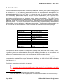
1 Introduction
The Infrared Sea surface temperature Autonomous Radiometer model 5 (ISAR-5) has been developed
to provide accurate and reliable measurements of the radiative sea surface temperature (SSTskin) to
an accuracy of ±0.1 K by measuring infrared emission from the sea surface and atmosphere in the
spectral waveband 9.8-11.5µm (see Table 1.1), without the need for frequent operator intervention.
One of the major problems with obtaining accurate SSTskin measurements from ships has been
adequate environmental protection of delicate infrared radiometer fore-optics. Seawater spray or rain
can introduce significant errors and in extreme cases, destroy instrumentation. The ISAR-5 system
has been specifically designed to address these problems and to provide a self calibrating infra red
radiometer system that can operate autonomously for extended periods when deployed from a ship of
opportunity (SOO). As SSTskin measurements benefit from being supplemented by other coincident
measurements in most applications, additional meteorological or oceanographic instrumentation can
be connected to the ISAR-5 system to provide a complete user specified measurement package.
Table 1.1 ISAR-5D Instrument Specifications
Spectral range
Response time
1
SSTskin Accuracy
2
Temperature range
Target angle range
Maximum continuous
deployment at sea
Min. deployment height
Calibration type
Output
Weight
Dimensions
Operating temperature
Power input
9.6-11.5µm
0.05-10s (user defined)
±0.1K rmse.
173-373 K
180° (nadir-zenith) in 0.1°
intervals (user defined)
3 months
7m above sea level
2 internal radiance cavities
RS232/NMEA style
Approx. 20 kg
Diameter 200mm x 500 mm
274 - 310 K (non-freezing)
24V DC
This operations manual describes the configuration, operation and deployment of an ISAR-53 system.
It is meant to be a user reference guide that provides sufficient information for you to configure and
begin making measurements with the ISAR system. For more detailed advice on set up and
maintenance procedures, please refer to the accompanying ISAR Procedures Manual.
Version 2 of this manual applies to an updated design of the instrument (designated ISAR-5D), which
incorporates the new electronics system designed by W. Wimmer in 2009. Users of ISAR instruments
based on the original electronics system (i.e. model ISAR-5C) should continue to refer to the ISAR
User Manual v1.11.
The following symbols are used within this manual:
M
Indicates useful information and tips to help you work with your ISAR
Indicates critical information that should be read carefully to avoid damage to the ISAR
instrument.
1
2
3
Depending on the appropriate value for the emissivity of seawater
Contact the ISAR team for advice regarding the use of the instrument outside of this temperature range
Note that henceforward the user manual will refer to the ISAR-5 instrument as ISAR.
Page 6 of 45
© Werenfrid Wimmer & Craig Donlon
ISAR-5D User Manual – Issue: 2.01
It is assumed that the user is competent in handling PC computers, software installation, basic Linux
commands, basic wiring of plugs and has an understanding of the principles and methodology of
making infrared measurements of the sea surface and atmosphere.
For further information regarding the premise behind the ISAR instrument, please refer to:
Donlon, C., Robinson, I.S., Reynolds, M., Wimmer, W., Fisher, G., Edwards, R. and Nightingale, T.J.,
2008. An Infrared Sea Surface Temperature Autonomous Radiometer (ISAR) for deployment aboard
Volunteer Observing Ships (VOS), Journal of Atmospheric and Oceanic Technology, 25, pp. 93-113.
Page 7 of 45
© Werenfrid Wimmer & Craig Donlon
ISAR-5D User Manual – Issue: 2.01
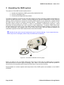
2 Unpacking the ISAR system
This section of the ISAR manual explains how to:
1. Unpack and repack the ISAR system and peripheral devices
2. Check for damaged items
3. Check that all components are present
The ISAR is shipped in a robust travel case that contains all of the necessary hardware and software to
operate the ISAR instrument. However, as each deployment requires consideration of local mounting
options, it will be necessary to construct a mounting cradle specific to your deployment. Please contact
the ISAR team for advice on suitable mounting options. Operational deployment of ISAR on a ship
demands careful thought and attention in terms of accessibility, measurement geometry, robust
instrument mounting brackets etc. and is specific to each deployment. In general, ISAR should view
the sea surface at an angle of ~25° from nadir (limiting the effect of angular variation of emissivity due
to ship movements), at a position that is free of the ship’s wake, and the distance between any
subsurface systems and the ISAR measurement should be recorded.
Handle all items with care and inspect each one for obvious damage.
If you suspect that any
ISAR component is damaged, please notify the ISAR team immediately.
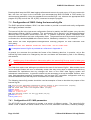
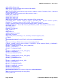
Figure 2-1. The ISAR-5 radiometer and rain gauge.
Before you begin to use your ISAR, please take some time to check that your ISAR system is complete
and that there are no obvious signs of damage. Use Table 2-1 to ensure that all items are present in
the box when first unpacking and contact the ISAR team if any items are missing.
Documentation on various aspects and components of the ISAR system are available on the ISAR-5
CD-ROM.
Page 8 of 45
© Werenfrid Wimmer & Craig Donlon
ISAR-5D User Manual – Issue: 2.01
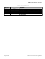
Table 2-1. ISAR-5D component list.
ISAR5D-C01
ISAR5D-C02
ISAR5D-C03
ISAR5D-C04
ISAR5D-C05
Number
supplied
1
1
1
1
1
ISAR5D-C06
1
Item code
Page 9 of 45
Description
ISAR-5D instrument
Thies Clima precipitation sensor & cable (optical rain gauge)
Trimbell GPS magnetic antenna
Power & communications pigtail for ISAR-5D
KT15 lens mount for laser module
CD-ROM containing component operating manuals, software
and documentation
© Werenfrid Wimmer & Craig Donlon
ISAR-5D User Manual – Issue: 2.01
3 Getting Started
3.1 Connecting the ISAR system
This section of the ISAR manual explains how to:
1. Connect the precipitation sensor to the ISAR instrument. (Please note that throughout this
manual the precipitation sensor is referred to generically as the optical rain gauge or ORG).
2. Connect the GPS antennae to the ISAR instrument
3. Connect a power supply to the ISAR instrument
4. Connect external user RS485 devices to the ISAR instrument
5. Connect the ISAR to a computer
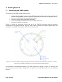
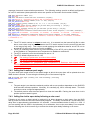
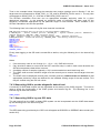
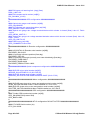
Figure 3-1 shows the electronics housing end cap of the ISAR-5D instrument and the necessary
connections to the external devices. Use this as a guide to connect the ISAR-5D system noting the
orientation of the ISAR-5D using the 4 LED indicators as a guide.
Figure 3-1 View of the ISAR end plate showing how external connections are made to the instrument. Use the
position of the indicator panel lights to correctly orientate the ISAR-5D body.
Connect each of the peripheral devices to the ISAR instrument as shown in Figure 3-1 ensuring that
the connections are well made. Wiring tables are given for each peripheral device in the following
sections.
Page 10 of 45
© Werenfrid Wimmer & Craig Donlon
ISAR-5D User Manual – Issue: 2.01
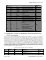
3.2 Peripheral device wiring schedule
3.2.1 Optical rain gauge wiring
The optical rain gauge socket is wired according to Table 3-1.
Table 3-1 Optical rain gauge socket wiring schedule
Pin number
Wire colour
Purpose
1
2
3
4
5
6
7
8
Screen
Black
Purple
Yellow
Brown
White
Not used
Ground
Analogue Signal 1
+12Volt DC
Analogue signal 2
Analogue Ground
Not used
Not used
3.2.2 Communication, Power and GPS antennae wiring
The communications interface, power and GPS antennae socket is wired according to Table 3-2.
Table 3-2 The communications interface, power and GPS antennae socket wiring schedule
Page 11 of 45
Pin number
Wire colour
Purpose
Coax
1
2
3
4
5
6
7
8
9
10
11
12
13
14
15
16
17
18
19
20
21
22
Black
Red/Blue
Orange/Green
White/Green
Yellow/Green
White
Yellow
Black
Blue
Red
Cyan
White/Blue
Yellow/Green/Blue
Red/Brown
Pink
Purple
Green
Brown
Grey
Green/Red
Yellow/Red
White/Red/ Orange
Red/Black
GPS antennae
Not connected
Not connected
Not connected
Not connected
Ethernet TX + (1)
Ethernet TX – (2)
Ethernet RX + (3)
Ethernet RX – (6)
RS422 TX +
RS422 TX RS422 RX +
RS422 RX RS 232 GND
RS 232 TX
RS 232 RX
RS485 12V GND
RS485 12 V Power
RS485 TX +
RS485 RX POWER GND
POWER IN 24V
POWER GND
© Werenfrid Wimmer & Craig Donlon
ISAR-5D User Manual – Issue: 2.01
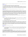
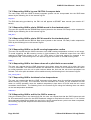
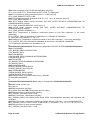
Figure 3-2: LEMO EGG.3K.822 socket view from the solder side.
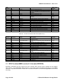
Serial interface communication settings are shown in Table 3-3.
Table 3-3 Serial communications parameters for ISAR serial interface
Name
Setting
Baud
Data Bits
Stop Bits
Parity
Handshake
115200
8
1
None
None
The ISAR on-board computer is a Eurotech Titan manufactured by Eurotech. Further information can
be found at http://eurotech-ltd.co.uk.
For operational deployments, use an uninterruptible power supply.
M
Ensure that the correct voltage is set on the power supply unit (24 V DC) Always use an
uninterruptible power supply with a current limit facility. If the input power falls below 15V DC the
on board computer may require a hard power reset (see Appendix C) as the internal registers may
be corrupted. This may be difficult to determine as the ISAR system and operational code
may continue to operate. However, all data registers within the system may be corrupt and
therefore the data will be incorrect!
MISAR
should draw about 0.5-0.7 A during normal operations and ~1 – 1.2 A during motor
operations. If excessive current is drawn, immediately power off and contact the ISAR team for
advice and assistance.
Page 12 of 45
© Werenfrid Wimmer & Craig Donlon
ISAR-5D User Manual – Issue: 2.01
4 General precautions when handling your ISAR instrument
This section of the ISAR-5D manual describes how to work safely with your ISAR instrument and
explains a number of precautions that should be taken prior to powering up your ISAR for the first time.
1. Double check that all connections to your ISAR are made correctly in accordance with section 3
of this manual.
2. Use an appropriate cradle to secure your ISAR before power up. The ISAR storm shutter may
be damaged if not properly protected. Ensure that the shutter is free to rotate whilst in the
laboratory or when deployed.
3. Be aware that the torque on the ISAR storm shutter is significant. M There is a risk of
severe injury if the user traps fingers in the ISAR storm shutter. In addition, significant damage
to the storm shutter mechanism will occur if the shutter traps a foreign body.
4. The ISAR instrument is normally delivered with the storm shutter in the closed position.
M
Be aware that this may open automatically on power up.
5. The RS485 connector carries 12 V DC power. Ensure that the contacts, as described in section
3.2.2, are properly isolated when not in use.
M
Be aware that the ISAR instrument weighs ~20 kg. Care should be taken when lifting or
moving the instrument.
7. When the shutter is open, the scan drum unit will rotate to view various target views and each of
the ISAR calibration blackbody units that are located inside the ISAR. It is normal for the scan
drum to operate like this. Ensure that the scan drum aperture is protected from the ingress of
foreign objects, as these may damage the ISAR scan mirror and Zinc Selenide window.
6.
Page 13 of 45
© Werenfrid Wimmer & Craig Donlon
ISAR-5D User Manual – Issue: 2.01
5 ISAR software installation
This section of the ISAR manual explains how to install the ISAR software on a computer that will be
used to control the ISAR instrument
Install the operational software provided on the ISAR CD-ROM following the instructions provided in
the README.TXT file. Typically, the ISAR code is copied to a directory with the structure defined in
Table 5-1:
Table 5-1 Directory structure of the ISAR-5D software distribution
Directory structure
Contents and purpose
\doc\ISAR
Contains the ISAR manual
The manuals for the onboard computer, the PNI module and the
Trimble GPS module
Contains Linux ARM executable files and ISARTOOLS file
Contains ISAR configuration file (these are instrument specific)
Contains the ISAR data logger software
Contains the ISAR post processing software and the instructions on
how to install python.
\doc\manuals
\software\ISOC
\software\isarconf
\software\IIDL
\software\post_processing
In order to successfully communicate with ISAR via the serial port, the user must ensure that an
appropriate serial terminal program (e.g. PuTTY) is installed on the computer that will be used to
control the instrument.
Page 14 of 45
© Werenfrid Wimmer & Craig Donlon
ISAR-5D User Manual – Issue: 2.01
6 Communicating with and testing the ISAR
The ISAR instrument is shipped with a basic diagnostic program called ISARTOOLS that can be used
for ISAR system familiarisation and to test the instrument functionality. ISAR allows considerable
flexibility for defining how the instrument will make measurements. This section of the manual explains
how to:
1. Interact with the ISAR instrument using a terminal emulator;
2. Test the ISAR system
6.1 Using the ISAR for the first time
The ISAR requires connection to a personal computer running Microsoft Windows or LINUX operating
system in order for the user to be able to interact with and/or modify the basic configuration of the
instrument. The ISAR onboard computer is a stripped down Red Head Linux computer that supports
SFTP and SSH communication. It can communicate with a host computer either through a serial port or
via an Ethernet connection.
On initial power up the ISAR should automatically run the ISAR Operating Code (ISOC) software that is
stored in the onboard flash disc. In addition, the LED configuration of ISAR can be used to obtain the
status of the instrument on power up (see Figure 6-1 and Table 6-1 for more information).
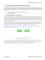
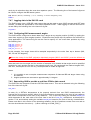
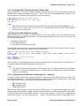
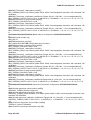
The ISAR has a small panel of light emitting diodes (LED) to indicate the operational status of
the instrument shown in Figure 6-1.
Figure 6-1 ISAR-5D status lights layout
Figure 6-1 shows the layout of the LED status lights whilst Table 6-1 (below) describes their function.
The LEDs will normally be orange if both possibilities are switched on except during the boot procedure
when LED 1 alone will be orange as the instrument boots from the ISOC software.
Page 15 of 45
© Werenfrid Wimmer & Craig Donlon
ISAR-5D User Manual – Issue: 2.01
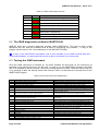
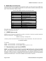
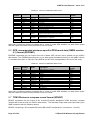
Table 6-1 ISAR-5 status lights function
LED
Colour
Description
1
Green
Indicates that the ISOC is running.
1
Red
Indicates an error.
2
Green
BB2 heater on/off (lit/unlit)
2
Red
BB1 heater on/off (lit/unlit)
3
Green
KT15 power on/off (lit/unlit)
3
Red
Spare power on/off (lit/unlit)
4
Green
Scan motor moving
4
Red
Shutter motor moving
6.2 The ISAR diagnostics software (ISARTOOLS)
ISAR-5D ships with a generic diagnostic program called ISARTOOLS. This can be used to help
familiarize the user with the instrument and to assist in diagnosing any problems. A copy of this
program can be found in the \bin subdirectory of the ISAR-5D CD-ROM.
A copy of the ISARTOOLS executable code is also available on the ISAR onboard flash disc
(/home/isar/software). It is assumed that the user is able to use basic Linux commands.
6.3 Testing the ISAR instrument
Once the ISAR instrument is switched on, the ISOC software will boot and run the instrument as
specified in the isarconf.cfg file on the SD card. In order to run the ISARTOOLS program, the ISOC
has to be stopped by either pressing Y during the startup (before the ISOC reads the isarconf.cfg file)
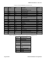
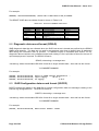
or by pressing Q after the startup routine has finished. Table 6-2 describes the command set of the
ISARTOOLS program.
Table 6-2 Command set for the ISARTOOLS
Key
Description
Expected result
a
A
c
d
D
A-D converter single channel voltage
A-D converter all channels voltages
Open and close shutter n times
Closes the ISAR-5C shutter
Opens the ISAR-5C shutter
e
Reads the position of the scan drum
E
Move the scan drum to a given angular position
g
Read data from the GPS unit
k
Send a command to the KT15.85D
Requires channel number input (0-31). Outputs channel voltage
All 32 channel voltage readings
Requires n input. Shutter motor opens shutter n times
Closes the shutter
Opens the shutter
Prints scan drum angular position (degrees) with reference to the
set zero position (see F)
Moves the scan drum to the angular position (degrees) you
provide with reference to the set zero position (see F)
Prints raw data read from the GPS unit (See section 8)
Prints a reply string from the KT15 (See KT15 manual for more
information)
K
L
o
p
Send KT15 configuration to KT15.85D unit
Switches faceplate LEDs on/off
Config PNI
Reads data from the PNI compass module
P
Sends a command to the PNI compass module
q
r
R
s
S
T
v
Exit the ISARTOOLS program
RS485 command
Runs RS485 as defined in configuration file
Scan test
Scan test
Reading temperatures
Toggle thermistor reference voltage on & off
Page 16 of 45
Requires LED number input. Selected LED switches on or off.
PNI will be configured
Prints data to the screen (See section 8)
See the PNI TCM-2 manual for more information. Used to set up
the PNI TCM-2 module prior to use in ISAR)
Returns to main menu
Scans BB and outputs results to SD flash card
Default scan of hot BB and outputs results to SD flash card
Output BB & thermistor temperatures to screen
© Werenfrid Wimmer & Craig Donlon
ISAR-5D User Manual – Issue: 2.01
Key
Description
V
Read all supply voltages
Expected result
Once ISARTOOLS has been started, the user should be presented with a menu of options. A
command is executed by typing a letter (case sensitive). Some commands have additional
requirements and the user will be prompted by the program to enter appropriate data (refer to the
command menu in Table 6-2 above for a summary of the available command set). The user will be
returned to the menu screen after the execution of any command
The ISARTOOLS program can be used to test the ISAR-5D instrument to ensure that no damage has
occurred during transportation. The following tests should be executed:
•
•
•
•
•
•
•
•
Check that the LEDs function (command L).
Check that the shutter opens and closes (commands d and D). Check that the shutter opens
completely and closes completely and that excessive current is not drawn during this operation
(check the ampere meter on the power supply). Shutter movement should be smooth and the
motors should maintain a steady speed.
Check that the scan drum rotates and meaningful shaft encoder data is reported. This is best
achieved by using the software to set the scan drum to point at an angle of 4.5°. Once the scan
drum is in this position, the edge of the viewing aperture hole should line up exactly with the
back face of the ISAR-5D body.
Check that the KT15 reports meaningful data (typical values of ~ 0.5 V at room temperature
when set to use a range of –100ºC to 100ºC would be expected)
Check the black body heater circuits by first switching each BB heater off and collecting some
data. Then turn each BB heater back on again and collect data (you may have to wait a few
minutes for the BB’s to warm up a little).
Check the rain sensor. Moving your fingers in front of the sensor should be sufficient to
generate a test signal.
Check the PNI sensor by moving the ISAR instrument into different angular positions in both the
vertical and horizontal plane.
Check the GPS unit. Note that you will need to have the antenna connected and located in a
position where GPS satellites can be seen to obtain meaningful data.
Should any test fail please contact the ISAR team immediately.
Once you have successfully completed all the diagnostic tests, the ISAR-5D is ready to use.
Page 17 of 45
© Werenfrid Wimmer & Craig Donlon
ISAR-5D User Manual – Issue: 2.01
7 Using the ISOC operational data logging software
ISAR is designed to allow considerable flexibility in defining how the instrument will make
measurements for an operational deployment. This is achieved through the ISAR Operating System
(ISOC). This section of the user manual explains how to:
1.
2.
3.
4.
Mount the ISAR SD card
Access the ISAR SD card using Linux commands
Upload a new ISOC executable program to the onboard computer
Configure the ISOC software to make user defined measurements
The root username and password are supplied on the accompanying ISAR CD-ROM and can also be
found in the FAQ section of this manual.
7.1 Mounting the SD card
The onboard SD card can be mounted using a normal Linux prompt as follows:
7.2 Accessing the ISAR SD card
The ISAR system has an internal 2GB SD card that can be used to store programs, configuration files,
calibration information and data files. The SD card can be accessed using standard Linux commands.
The standard mount point is /data. File editing can be achieved using a suitable file-editing programme
such as Nano.
7.3 Uploading a new program onto the ISAR instrument
Before any program can be executed, the program must be uploaded into the appropriate directory of
the onboard computer (/home/isar/software) using standard Linux commands.
7.3.1 Loading a new operational code or configuration file onto ISAR
To load a program onto the ISAR the user can SFTP into the instrument using the instrument IP
address and upload the required file, using standard Linux commands, to the /home/isar/software
directory.
7.3.2 Stopping the ISAR resident data logging program
When the ISAR is powered up, the ISOC data logging program will automatically run. The initial factory
configuration of the ISOC code will make a SSTskin temperature measurement using a target view
angle of 45º from nadir for the sea, 45º from zenith for the sky, using a sea water emissivity of 0.98.
However, for most deployments this configuration is not optimal and needs to be changed before
acquiring data for scientific purposes.
Page 18 of 45
© Werenfrid Wimmer & Craig Donlon
ISAR-5D User Manual – Issue: 2.01
Pressing Q will stop the ISOC data logging software and return to the main menu. If for any reason this
fails, the user can logon to the instrument (see accompanying ISAR CD-ROM or FAQ section for
username and password). Using the standard Linux command (ps –ax), discover the appropriate ISAR
program ID (PID) and use the ‘kill -9 {PID}’ command to stop the program.
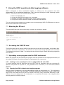
7.4 Configuration of ISAR: Using the isarconf.cfg file
The ISAR operational software, ISOC, has been written to provide a versatile and easily configurable
data logging software interface.
The isarconf.cfg file is the instrument configuration file that is read by the ISAR system every time the
data logging program (ISOC) is started. The configuration file is stored in the /home/isar/software/
directory and is a specific format ASCII text file. It contains instrument specific calibration data,
component identifications and user configuration fields. The general format of the isarconf.cfg file is for
a comment line, denoted by #### at the start of the line, followed by a data line. For example:
#### Title for this deployment/configuration stating purpose of this isarconf file
(str[255])
TITLE=icf file for ISAR-06 valid for isar linux -v2.0.0 code base
A complete isarconf.cfg file is provided as a reference in Appendix A.
In general, the comment line provides the format of the following data line. In practice, only a few
isarconf.cfg fields need to be changed by the user and these are discussed by task in the following
sub-sections.
M
Modifying any of the calibration data entries within the isarconf.cfg file may result in either your
ISAR refusing to boot or incorrect results. ALWAYS make a backup copy of the current isarconf.cfg
file.
The fields that require user editing are provided at the start of the isarconf.cfg file. Most entries should
not be changed unless the user is absolutely certain that they know what is required and that they
understand the implications that any changes will have on the ISOC data logging system and
subsequent measurements. In general it should only be necessary to set up the header sections, scan
drum and associated sampling characteristics, the real time SST calculation configuration and any
external RS485 devices that may have connected to the ISAR instrument.
The following isarconf.cfg entries should be used as examples of how to describe the purpose of the
isarconf.cfg file:
#### Title for this deployment/configuration stating purpose of this isarconf file (str[255])
TITLE=icf file for ISAR-06 valid for isar linux -v2.0.0 code base
#### ICF author name, e-mail and telephone number (str[255])
AUTHOR=W Wimmer
[email protected]
PHONE=+44 (0)2380 597654
#### Last Edit date of this icf file yyyy-mm-dd (str[15])
EDITDATE=2011-06-08
#
LOGFILE_PATH=/data/
7.4.1 Configuration of KT15.85D parameters
The KT15.85D may be configured to operate in a variety of different modes. The isarconf.cfg file
allows a user to define the serial number of the KT15 unit, calibration information, emissivity settings,
Page 19 of 45
© Werenfrid Wimmer & Craig Donlon
ISAR-5D User Manual – Issue: 2.01
response times and communication parameters. The following settings provide a default configuration
for a KT15 radiometer (these particular values are specific to instrument serial number 10200):
#### KT15.85D Serial number (int)
KT15_SN=10200
#### Date and details of KT15.85D last calibration (str[255])
KT15_CAL=2007-05-11, Polynomials for R2T & T2R: TJ Nightingale 2003-06-04
#### KT15 emissivity setting command (0.001 -> 1.000) (str[15])
KT15_CMD_EMISIVITY=EPS 1.000
#### KT15 response setting command (0.05, 0.1, 0.3, 1 3 or 10 seconds) (str[15])
KT_CMD_RESP=RESP 1.0
#### KT15 analog output setting command (Do you know what you are doing ?) (str[30])
KT15_CMD_ANALOG=ANALOG -100.0 50.0 C 3
#### KT15 serial interface setting (Do you know what you are doing ?) (str[20])
KT_CMD_SERIAL=COM 96 8 1 n
#### KT15 Temperature to Radiance coefficients based on kt15 filter response (-1 not used) (double[9])
KT15_COEFF_T2R=-22.925646e0, 65.196703e0, -81.215855e0, 56.792568e0, -21.105313e0, 3.2575460e0,-1.0,1.0,-1.0
#### Radiance to Temperature coefficients based on kt15 filter response (-1 not used) (double[9])
KT15_COEFF_R2T=273.15973e0,54.529628e0,10.634341e0,2.0172007e0,3.6480705e-1,5.7776974e-2,6.5293295e3,3.5814663e-4,-1.0
Notes:
1. The KT15 serial number is unique to each unit. It is entered into the isarconf.cfg file in order
that a cross check may be made between the KT15 serial number from the actual unit and that
in the isarconf.cfg entry. This helps to avoid applying the calibration data for one KT15 unit to
another KT15 when more than one unit is available.
2. The KT15 calibration date refers to the last calibration of the KT15 unit by Heitronics and refers
to the Radiance to Temperature and Temperature to Radiance coefficients.
3. The KT15 emissivity value should always be set to 1.0
4. The KT15 default response time is 1.0s
5.
6.
7.
M
M
M
The analogue parameters should not be modified
The Serial interface parameters should not be modified
The Radiance to Temperature and Temperature to Radiance data should not be
modified. These are specific to each KT15 unit and are calculated from the calibration data
provided by Heitronics.
7.4.2 Setting the ScanDrum park angle
The scan drum park angle refers to the default angle at which the scan drum will be placed when the
ISAR shutter is closed. It is set using the following line of the isarconf.cfg file:
#### A2 encoder park angle (normally over lower blackbody) (float,deg)
ENCODER_PARK=280.0
Notes:
1. The park angle is an absolute rotational position with a zero position dependent on the ISAR-5D
shaft encoder reference position. Normally, 0 is vertically up, 180 is vertically down. The shaft
encoder must be configured appropriately.
2. The default position sets the scan aperture to view the lower BB. Parking the scan drum in this
position prevents water ingress.
7.4.3 Setting the shutter open delay following a rain event
Following a rain event, a delay period is required (a) to allow rainwater to drain away from the ISAR
and (b) to be sure that the rain event has actually stopped. The delay is entered as n cycles where the
delay time is approximately calculated as n*2 seconds. A recommended choice of delay is n ~350. If
you are working with the ISAR in the laboratory for a calibration, then a rain event delay is not required.
Use the following line of the isarconf.cfg to reduce the shutter open delay following a rain event:
Page 20 of 45
© Werenfrid Wimmer & Craig Donlon
ISAR-5D User Manual – Issue: 2.01
#### Number of cycles (n) to wait after rain event has finished (time is ~n*2 secs.
(int)
ORG_OPEN_DELAY=350
Lab=60 Field= ~350)
7.4.4 Setting the Optical Rain Gauge shutter trigger threshold
The Optical Rain Gauge (ORG) is used to trigger the ISAR shutter mechanism and close the
instrument down if rain or sea spray is detected. The ORG has a background noise level above which
a rain/spray event becomes significant. This is set using an ORG voltage threshold using the following
isarconf.cfg line:
##### Optical rain gauge rain voltage threshold below which shutter is closed (float). Field~1.1
ORG_MEAN_LIMIT=1.1
During long deployments some surface contamination of the ORG optical system may occur and the
voltage threshold value should be set with some margin of tolerance to allow for this. However, this
may result in an increased possibility of ISAR not closing down quickly enough once a rain/spray event
has been detected. Typically, a rain event is characterized by a significant increase in the standard
deviation of the signal and therefore a second threshold can be set to trigger the ISAR shutter, based
on the standard deviation of the ORG signal. This second check is determined by calculating the
standard deviation of 25 ORG measurements and comparing this against a threshold value. The
following lines of the isarconf.cfg file may be used for this purpose:
#### Optical rain gauge rain voltage standard deviation above which shutter is closed (float).Lab =5,
Field= 1.2
ORG_SD_LIMIT=5
Notes:
1. The voltage mean threshold should be verified by basic tests before any unattended
deployments at sea. A value of 1.0-1.2 is typical.
2. The current signal is within the range 4 mA- 20 mA and passes through a 220Ω resistor so that
880 mV represents no rain.
7.4.5 Setting the Shaft Encoder Reference position
The shaft encoder reference position must be set to allow the ISAR scan drum to position itself
correctly. A simple method to check the configuration is to use the Prot software to carefully position
the rear edge of the scan drum aperture flush against the back wall of the ISAR body so that it is
looking vertically up and along the central cutaway. The scan drum position should read 355.5° in this
position. If this is not the case, an appropriate offset from zero may be set using the following
isarconf.cfg line:
#### A2 encoder reference position (float,deg)
ENCODER_REF=0.0
Notes:
1. If the Scan drum positions are inconsistent it may mean that the shaft encoder has lost its
internal configuration. This can be reset using the encoder setup software provided on the
software CDROM.
2. Ensure that the scan drum aperture is lined up as accurately as possible using this method.
7.4.6 Setting the heated black body
Both ISAR black body (BB) units are identical and both have a Kapton heater that can be used to heat
the BB cavity. In normal operation, one of the BB units is heated to above ambient temperature whilst
the other is allowed to remain at roughly ambient temperature. Normally, the upper (325º) BB unit
(BB2) should be selected as the heated BB since this points downward, preventing heat loss from the
Page 21 of 45
© Werenfrid Wimmer & Craig Donlon
ISAR-5D User Manual – Issue: 2.01
cavity by air advection when the scan drum aperture opens. The following line of the isarconf.cfg must
be used to configure the BB heater system:
#### Heated (Active) blackbody (1 or 2; Normally 2 unless changed by user)
HOTBB=2
7.4.7 Logging data to the ISAR SD card
The ISAR system has a 2GB SD card system that can be used to store ISAR average and SST data
records. All data are appended to a file called ISARDATA.DAT. Data logging to the SD card can be
turned ON by the following line in the isarconf.cfg file:
LOG_DATA=1
7.4.8 Configuring ISAR measurement angles
The ISAR can be configured to obtain data from a target at any angular position (0-360º) by setting the
scan drum angle to a given angular location. Experience has shown that 10 positions are sufficient for
most applications. The isarconf.cfg file can be used to specify 10 “set” scan drum positions by using
the following line:
SCAN_POS_1=280.0,30
SCAN_POS_2=325.0,30
SCAN_POS_3=25.0,10
SCAN_POS_4=155.0,40
In this example, four target views will be sampled sequentially in the order from top to bottom (280,
325, 25 and 155 degrees).
M Note that views of the ISAR calibration blackbody targets (280.0º and 325.0º) must be defined as
view angles here. Otherwise the ISAR will not function properly.
Note that both the view angle and the number of samples to be viewed at that angle must be specified
explicitly for each position so that in the example given here, 30 samples will be made at angles 280º,
and 325º, 40 samples at 155º but only 10 samples will be made at angle 25º.
Notes:
1. It is possible to set a complex measurement sequence of alternate BB and target views using
this method.
2. Angular positions are accurate to approximately 0.1 degree
7.4.9 Requesting ISAR to provide a real time SSTskin data record
The ISAR can also compute a real time SSTskin data record. This can be selected using the following
line of the isarconf.cfg file:
CALC_SST=1
In order for a SSTskin temperature to be properly derived from raw ISAR measurements, the
isarconf.cfg file must also specify which of the scan positions corresponds to the view of sea radiance
and which corresponds to the view of sky radiance. This is done by setting the variable SEAVIEW_POS
which depends on the rank order of the sea view in the list of SCAN_POS_n definitions, as described in
section 7.4.8, and similarly setting the variable SKYVIEW_POS based on the rank of the sky view definition.
Please note that in this version of the operating software, the list of positions counts from zero and so
the user should enter the value (n - 1) when referring to SCAN_POS_n.
Page 22 of 45
© Werenfrid Wimmer & Craig Donlon
ISAR-5D User Manual – Issue: 2.01
Thus in the example below, following the example scan position settings used in Section 7.4.8, the
target sea view corresponds to SCAN_POS_4 = 155, and so SEAVIEW_POS is set to 3. The sky view
corresponds to SCAN_POS_3 = 25.0 and so SKYVIEW_POS is set to 2.
The SSTskin calculation must also use an appropriate seawater emissivity value for a given
deployment geometry. In the example an emissivity value of 0.991635 has been used for the
emissivity of seawater appropriate for the particular angle of view selected. Other variables in the
SSTskin calculation can also be specified.
The following lines in the isarconf.cfg file show how this is achieved.
#### Defining variables that will be used to calculate SSTskin temperature;
# SEAVIEW_POS - seaview scandrum position; SKYVIEW_POS - skyview scandrum position;
seawater emissivity; RMR_CORR - RMR x correction factor;
# VREF - reference voltage (0 if using internal voltage); RREF – reference resistance;
#INTBB_EMISSIVITY - internal BB emissivity; SELFHEAT_CORR - self heating correction on/off
SEAVIEW_POS=3
SKYVIEW_POS=2
EMISSIVITY=0.991635
RMR_CORR=1.0
VREF=0.0
RREF=10000.0
INTBB_EMISSIVITY=0.9993
SELFHEAT_CORR=0
EMISSIVITY
-
Finally, data logging to the SD card is turned ON as before, using the following line in the isarconf.cfg
file:
LOG_DATA=1
Notes:
1
2
3
4
5
If the emissivity value is out of range (i.e., < 0 or > 1.0), ISAR will not boot.
Care should be taken to ensure that the SST real time setup is valid in each case otherwise the
SSTskin temperature data will be incorrect.
A suitable number of samples (typically > 20) is recommended on each black body unit.
The ISAR shaft encoder reference angle must be correctly set to ensure that all target views are
correct.
The ISAR must be deployed correctly with a known geometry relative to the sea surface so that
appropriate emissivity values are defined for the intended viewing angle of the sea surface. This
may be verified using the PNI roll values.
7.4.10 Requesting ISAR to provide diagnostic data at boot
A summary of ISAR data outputs can be requested at the startup of the ISOC program. This can be
used to check the functionality of the ISAR system and isarconf.cfg file. The following line in the
isarconf.cfg file sets this function:
START_DIAGN=1
7.4.11 Requesting ISAR to log raw GPS data
The raw output from the ISAR on-board GPS system can be incorporated onto the ISAR data stream
by the following line in the isarconf.cfg file:
RAW_GPS=1
The GPS data string provided by the GPS unit will appear as $GPGGA or $GPRMC data records (see
section 8.5).
Page 23 of 45
© Werenfrid Wimmer & Craig Donlon
ISAR-5D User Manual – Issue: 2.01
7.4.12 Requesting ISAR to log raw PNI TCM-2 compass data
The raw output from the ISAR on-board compass system can be incorporated into the ISAR data
stream by the following line in the isarconf.cfg file:
RAW_PNI=1
The PNI data string provided by the PNI unit will appear as $PNIST data records (see section 8.7
below).
7.4.13 Requesting ISAR to print a $IS5MR record to the standard output
The user can request that the $IS5MR data record (stored on the internal SD card) is also outputted to
RS232 by the following line in the isarconf.cfg file:
MEAN_REC=1
7.4.14 Requesting ISAR to print a $I5CAL record to the standard output
The user can request that the $I5CAL data record (stored on the internal SD card) is also outputted to
R232 by the following line in the isarconf.cfg file:
CAL_REC=1
7.4.15 Requesting ISAR to run the BB crossing temperature routine
The user can request that the ISAR instrument runs a BB crossing temperature routine in a rain event.
To avoid triggering the BB crossing routine in light showers, the threshold output from the ORG
required to trigger the routine is set to ~2V (This value is fixed and cannot be changed in the
configuration file). The following line in the isarconf.cfg file can switch on the BB crossing event:
XTEMP=1
7.4.16 Requesting ISAR to shut down when roll or pitch limits are exceeded
The user can request that the ISAR instrument shuts down when the preset roll or pitch limit (see
7.3.19) is exceeded. The instrument follows the standard rain routine for the shutdown and will return
to normal operation once the roll or pitch reduces below the limit and the rain event countdown has
finished. The roll or pitch shutdown can be switched on by the following line in the isarconf.cfg file:
ROLL_PITCH_STOP=0
7.4.17 Requesting ISAR to shutdown for low temperatures
The user can request that that the ISAR instrument shuts down when the ambient temperature falls
below freezing (273.15K). The instrument uses the standard rain routine for the shutdown and will
return to normal operation once the ambient temperature rises above 273.15K and the rain event
countdown has finished. The following line in the isarconf.cfg file using the following lines can switch
on the low temperature shutdown:
FREEZING=1
7.4.18 Requesting ISAR to wait for the ORG to warm up
Using the following line in the isarconf.cfg file, the user can request that that the ISAR instrument wait
for 30 measurement cycles for the ORG measured voltage to drop below the limit set in 7.3.4. If either
the measured voltage drops below the set limit or the 30 measurement cycles have been completed,
the warming up loop will stop and the measurement loop start.
ORG_WARMING=1
Page 24 of 45
© Werenfrid Wimmer & Craig Donlon
ISAR-5D User Manual – Issue: 2.01
7.4.19 Changing PNI TCM-2 pitch and roll alarm limits
During deployment, if the ship exceeds defined pitch and roll limits, the ISAR system will flag the
$ISAR5 data records accordingly using the 7th and 8th bits of the StatusWord (see section 8) The
following lines of the isarconf.cfg file set these pitch and roll limits:
# PNI sensor pitch warning limit (deg) (float)
PITCH_LIMIT=2.0
# L23: PNI sensor roll warning limit (deg) (float)
ROLL_LIMIT=2.0
Notes:
1. Pitch and roll limits are used to provide warnings only, reported via the StatusWord bits 7-8
2. If ROLL_PITCH_STOP (see 7.3.16) is set to 1, the instrument will shut down (ISAR behaves
like it would in a rain event).
7.4.20 Using the ISAR RS485 sub-system
ISAR allows for the connection of RS485 devices to the main system and to log data from these
devices directly into the ISAR data stream. The following parameters must be set in the isarconf.cfg
file for each RS485 device:
(α) A label for the device
(β) The RS485 address
(χ) The device specific read command
Each RS485 device should be configured to an appropriate baud rate, with no stop bits and no parity.
The following isarconf.cfg lines allow for RS485 configuration:
#### Up to 8 External RS485 devices can be sequentially defined.
# RS485_n_NAME - label for device; RS485_n_ADDRESS - RS485 address; RS485_n_COMMAND - device specific
read command;
RS485_1_NAME=RhoPD_D1102_CM11_Solarimeter
RS485_1_ADDRESS=4
RS485_1_COMMAND=$4RD
In this example, a single RS485 device has been configured with the title
is located at address 4 and the data read command is 4RD.
RhoPD_D1102_CM11Solarimeter.
It
Notes:
1. The present system assumes that a numeric data value is received, prefixed by an identifier
character (* is the RhoPoint default return). Please contact the ISAR team for specific requests
if this is not appropriate.
7.4.21 Configuration of ISAR basic measurements - summary
In order to record a basic set of radiance and SST measurements, the ISAR instrument needs to be
configured appropriately. The ISOC data logging program collects data in measurement cycles, with
each measurement cycle consisting of the following measurements:
•
•
•
BB1 calibration data
BB2 calibration data
Target observations
Note that the ISOC program allows the user to select up to 10 programmable target scan drum
positions that are specified as angles. ISAR-5D must first collect n measurements whilst viewing BB1,
n measurements whilst viewing BB2 and then, for each target position, it will make x measurements
before moving on to the next target position. Finally, n measurements whilst viewing BB1 and n
Page 25 of 45
© Werenfrid Wimmer & Craig Donlon
ISAR-5D User Manual – Issue: 2.01
measurements whilst viewing BB2 will be made to ensure that a meaningful calibration trend can be
established over the measurement period. Each sample takes approximately 1 second to collect
(without additional instruments attached to the RS485 port).
Use the following decision checklist to setup ISAR to make your measurements:
•
•
•
•
•
•
What scan drum angles need to be set, including viewing the BBs?
How many samples are required at each scan drum position?
Should the data be logged to the internal SD card?
Should an SSTskin measurement be made (if so setup the calculation)?
Should GPS data be logged?
Should PNI data be logged?
The ISOC data logging program will:
•
•
•
•
Check and initialise each of the ISAR systems;
Read the user defined configuration settings for this execution from the isarconf.cfg file stored
on the ISAR SD card;
Write the current instrument configuration in the data stream;
Begin logging data.
Page 26 of 45
© Werenfrid Wimmer & Craig Donlon
ISAR-5D User Manual – Issue: 2.01
8 ISAR data record format
The ISAR data stream is a formatted comma separated variable (csv) data record with an NMEA style
ASCII string output. Several NMEA style identifiers are used to define the different ISAR5 data record
types. These are defined in Table 8-1 below.
Table 8-1 ISAR-5 NMEA style data record identification labels
NMEA style identifier
Description
$ISMSG
$ISAR5
$IS5MN
$I5SST
$I5CAL
A comment or message string
A standard ISAR-5 data record
An averaged ISAR-5 data record
A SSTskin data record for real time operations
Calibration data used to compute real time SST
measurement provided in $I5SST
GPS fix data (NMEA version 2.1)
GPS data: Recommended minimum Specific
GPS/Transit data
TCM2 Electronic compass data record
Diagnostics test outputs
A data record containing external RS485 device
outputs
Configuration data and messages relating to the
isarconf.cfg configuration file
A warning message for consideration
Additional information beyond scope of $ISAR5
Debug information
ISAR error message. Problem needs addressing.
ISAR status message
ISAR scan information
A-D converter message
$GPGGA
$GPRMC
$PNIST
$IDIAG
$IS485
$ISCFG
$IWARN
$ISHCG
$DEBUG
$ISERR
$ISTAT
$ISSCN
$IS5AD
Each data record type is fully expanded in the following sections. Note that these records are valid for
the ISOC v2.0 code base and above.
8.1 $ISMSG data records
$ISMSG strings will appear in the data file to provide an indication of warnings or general operational
status of the instrument. The $ISMSG format is
$ISMSG,<timestring>,<message text>
<timestring> takes the standard ISO 8601 format for a single variable date + time and has the format
YYYYMMDDTHHMMSS
For example:
$ISMSG, 20110727T103046Z, Initialising DMM32 ..
$ISMSG, 20110727T103046Z, Setting DMM32 digital ports to zero
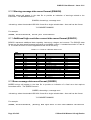
8.2 Standard data record format ($ISAR5)
$ISAR5 is a standard ISAR data record that is produced approximately every second by the ISAR
system. Each sensor on board the ISAR is read and the data value stored in the lowest processed
state. This constitutes the level-0 engineering data output. The format of an $ISAR5 record is fully
described in Tables 8-2 and 8-3. If any external RS485 devices are attached to ISAR that are correctly
configured in the isarconf.cfg file, a $IS485 data record will be produced to output the measurements
made by each RS485 device. The format of a $IS485 record is shown in Table 8-4.
Page 27 of 45
© Werenfrid Wimmer & Craig Donlon
ISAR-5D User Manual – Issue: 2.01
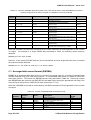
Table 8-2. Format of $ISAR5 data record (ISOC-v2.0)
CSV
Position
Example
0
$ISAR5
1
20110727T103129Z
yymmddThhmmssZ
2
3
4
5
6
7
8
9
10
25.02
0.0603
0.7025
1.7525
1.7386
1.7353
2.3296
2.3284
2.3295
Degrees
mV
mV
Counts
Counts
Counts
Counts
Counts
Counts
11
2200
Counts
12
13
14
15
16
17
18
19
20
21
22
23
24
25
26
27
28
29
30
31
32
2000
2300
1200
1900
1977,
2612
3795
0
1
-3.1000
1.1000
181.70
22.5
50.893501
-1.39583
11.0
32.4
4.2
289.1
290.2
23634128
Counts
Counts
Counts
Counts
Counts
Counts
Counts
0 or 1
0 or 1
Degrees
Degrees
Degrees
Degrees
Degrees
Degrees
Knots
DegreesT
Degrees
Kelvin
Kelvin
(see table 4.2 below)
33
06/10200
ISARID/KT15ID
Units
Description
Format
NMEA style identifier
ISO 8601 time string
YearMothDayTHourMinuteSecondZ
Scan drum position
Optical rain gauge signal
KT15.85D signal
BB1 thermistor 3 (base)
BB1 thermistor 2 (base)
BB1 thermistor 1 (aperture)
BB2 thermistor 3 (base)
BB2 thermistor 2 (base)
BB2 thermistor 1 (aperture)
5 Volt reference voltage for BB thermistors (should be
~2200 +/- 100counts)
BB Aperture thermistor 1
BB aperture thermistor 2
BB aperture thermistor 3
KT15 external case thermistor
ZnSe window thermistor
TT8 computer board thermistor
Input power
Shutter switch 1
Shutter switch 2
Pitch
Roll
Azimuth
PNI board temperature
Latitude
Longitude
Speed over ground
Course made good
Magnetic variation
KT15 target temperature measurement
KT15 internal reference temperature
Record status flags
Serial number of ISAR instrument and serial number of
KT15 instrument
String
Integer
Float
Float
Float
Float
Float
Float
Float
Float
Float
Integer
Integer
Integer
Integer
Integer
Integer
Integer
Integer
Integer (1 active)
Integer (1 active)
Float
Float
Float
Float
Float
Float
Float
Float
Float
Float
Float
Long
Char
Table 8-3. Interpretation of the $ISAR5 data record status word bit field (ISOC-v2.0)
Bitfield
position
0
1
2
3
4
5
6
7
8
9
10
11
12
13
14
15
Page 28 of 45
Description if set
Data collected in a rain event
GPS data are bad
PNI data are bad
TT8 clock reset from GPS
Rain detected by ORG
Shutter is Closed
Optical rain gauge data are
bad
PNI roll limit exceeded
PNI pitch limit exceeded
RS485 data present in data
record
Bad data from 18 bit A/D
Bad scan drum position
Not used
Not used
Not used
Not used
© Werenfrid Wimmer & Craig Donlon
ISAR-5D User Manual – Issue: 2.01
Table 8-4. Format of a $IS485 data record (ISOC-v2.0). Note that at least 1 external RS485 device must be
correctly configured in the isarconf.cfg file for a $IS485 record to be produced.
CSV
Position
Example
0
$IS485
1
20030523T134544Z
yymmddThhmmssZ
2
Ch 0:*+2.33
Various
3
Ch 1:*+ 0.0045
Various
4
Ch 2:*+109.2
Various
5
Ch 3:*+10.3
Various
6
Ch 4:*+1000.2
Various
7
Ch 5:*+0.234523
Various
8
Ch 6:*+0.023415
Various
9
Ch 7:*+7.456432
Various
n
1/4382
ISARID/KT15ID
Units
Description
Format
NMEA style identifier
ISO 8601 time string
YearMothDayTHourMinuteSecondZ
User defined RS485 device #0 outputs see bit 9
of Status flags
User defined RS485 device #1 outputs see bit 9
of Status flags
User defined RS485 device #2 outputs see bit 9
of Status flags
User defined RS485 device #3 outputs see bit 9
of Status flags
User defined RS485 device #4 outputs see bit 9
of Status flags
User defined RS485 device #5 outputs see bit 9
of Status flags
User defined RS485 device #6 outputs see bit 9
of Status flags
User defined RS485 device #7 outputs see bit 9
of Status flags
Serial number of ISARinstrument and serial
number of KT15 instrument (e.g.,1/4832)
String
Integer
String
String
String
String
String
String
String
String
Char
Note that a $IS485 record will be terminated by the ISAR instrument ID field regardless of the number
of outputs. For example if a single RS485 was connected to ISAR, the following output might be
obtained:
$IS485,Ch 0:99.234,1/4832
However, if two external RS485 devices (one multi-channel and one single-channel) were connected
the output would be obtained:
$IS485,Ch 0:*-99.234*+33.998,Ch 1:*+0.2333,1/4832
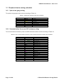
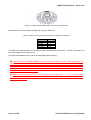
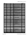
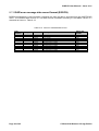
8.3 Averaged data record format ($IS5MN)
$IS5MN is an averaged ISAR data record. It consists of the mean value for a number of standard data
records obtained for a given scan drum position. A new $IS5MN data record is created for each new
scan drum position. The format of a $IS5MN record is fully described in Table 8-5. Users may request
that $IS5MN data are stored to the ISAR-5D SD card data file by setting the appropriate user flag in the
isarconf.cfg file stored on the ISAR-5D SD card (see section 7.3.13).
Note that a $IS5MN record will be terminated by the ISAR instrument ID field regardless of the number
of outputs.
Table 8-5. Format of a $IS5MN data record (ISOC-v2.0)
CSV
Position
Example
0
$IS5MN
1
20110727T103402Z
2
3
25.02
0.001
4
30
5
0.0603
Page 29 of 45
Units
yyyyddmmThh
mmssZ
Degrees
Degrees
mV
Value and
format
Description
NMEA style identifier
ISO 8601 time string
YearMothDayTHourMinuteSecondZ
Scan drum position
Scan drum position Standard deviation
Number of scan drum position measurements
averaged
Optical rain gauge signal
String
Integer
Float
Float
Float
Float
© Werenfrid Wimmer & Craig Donlon
ISAR-5D User Manual – Issue: 2.01
CSV
Position
Example
Units
Description
6
0.001
Degrees
7
30
8
9
0.7025
0.001
10
30
11
12
1.7525
0.001
13
30
14
15
1.7386
0.001
16
30
17
18
1.7353
0.001
19
30
20
21
2.3296
0.001
22
30
23
24
2.3284
0.001
25
30
26
27
2.3295
0.001
28
30
29
2200
Counts
30
0.001
Degrees
31
30
32
33
2000
0.001
34
30
35
36
2000
0.001
37
30
38
39
2000
0.001
40
30
41
2000
Counts
42
0.001
Degrees
43
30
44
45
1910,
0.001
46
30
47
2612
Counts
48
0.001
Degrees
49
30
50
51
3795
0.001
52
30
53
54
57
58
0
1
-3.1000
0.001
Standard deviation of optical rain gauge signal
Number of optical rain gauge measurements
averaged
KT15.85D signal
Standard deviation of kt15 signal
Number of kt15 signal measurements
averaged
BB1 thermistor 3 (base)
Standard deviation of BB1 thermistor 3
Number of BB! Thermistor 3 measurements
averaged
BB1 thermistor 2 (base)
Standard deviation of BB1 thermistor 2
Number of BB1 Thermistor 2 measurements
averaged
BB1 thermistor 1 (aperture)
Standard deviation of BB1 thermistor 1
Number of BB1 Thermistor 1 measurements
averaged
BB2 thermistor 3 (base)
Standard deviation of BB2 thermistor 3
Number of BB2 Thermistor 3 measurements
averaged
BB2 thermistor 2 (base)
Standard deviation of BB2 thermistor 2
Number of BB2 Thermistor 2 measurements
averaged
BB2 thermistor 1 (aperture)
Standard deviation of BB2 thermistor 1
Number of BB1 Thermistor 2 measurements
averaged
5 Volt reference voltage for BB thermistors
(should be ~2200 +/- 100counts)
Standard deviation of 5V reference
Number of 5V reference measurements
averaged
BB aperture thermistor 1
Standard deviation of BB aperture thermistor 1
Number of BB aperture thermistor 1
measurements averaged
BB aperture thermistor 2
Standard deviation of BB aperture thermistor 2
Number of BB aperture thermistor 2
measurements averaged
BB aperture thermistor 3
Standard deviation of BB aperture thermistor 3
Number of BB aperture thermistor 3
measurements averaged
KT15 external body thermistor
Standard deviation kt15 external body
thermistor
Number of kt15 external body measurements
averaged
ZnSe window thermistor
Standard deviation of ZnSe thermistor
Number of ZnSe thermistor measurements
averaged
TT8 computer board thermistor
Standard deviation of TT8 computer board
thermistor
Number of TT8 board thermistor
measurements averaged
Input power
Standard deviation of input power
Number of input power measurements
averaged
Shutter switch 1
Shutter switch 2
Pitch
Standard deviation of pitch measurement
Page 30 of 45
mV
Degrees
Counts
Degrees
Counts
Degrees
Counts
Degrees
Counts
Degrees
Counts
Degrees
Counts
Degrees
Counts
Degrees
Counts
Degrees
Counts
Degrees
Counts
Degrees
Counts
Degrees
0 or 1
0 or 1
Degrees
Degrees
Value and
format
Float
Float
Float
Float
Float
Float
Float
Float
Float
Float
Float
Float
Float
Float
Float
Float
Float
Float
Float
Float
Float
Float
Float
Integer
Float
Float
Integer
Float
Float
Integer
Float
Float
Integer
Float
Float
Integer
Float
Float
Integer
Float
Float
Integer
Float
Float
Integer
Float
Float
Integer (1 active)
Integer (1 active)
Float
Float
© Werenfrid Wimmer & Craig Donlon
ISAR-5D User Manual – Issue: 2.01
CSV
Position
Example
59
60
61
62
63
64
65
66
67
30
1.1000
0.001
30
181.70
0.001
30
22.5
0.001
68
30
69
70
71
72
73
74
75
76
77
78
50.893501
-1.39583
11.0
0.001
30
32.4
0.001
30
4.2
0.001
79
30
80
81
289.9
0.001
82
30
83
84
290.9
0.001
85
30
86-112
Float
Various
Degrees
N
0.001
30
06/10200
Units
Degrees
Degrees
Degrees
Degrees
Degrees
Degrees
Degrees
Degrees
Knots
Degrees
DegreesT
Degrees
Degrees
Degrees
Kelvin
Kelvin
Kelvin
Kelvin
ID/Serial
Value and
format
Description
Number of pitch measurements averaged
Roll
Standard deviation of roll measurements
Number of roll measurements averaged
Azimuth
Standard deviation of azimuth measurements
Number of azimuth measurements averaged
PNI board temperature
Standard deviation of PNI board temperature
Number of PNI temperature measurements
averaged
Latitude
Longitude
Speed over ground (SOG)
Standard deviation of SOG
Number of SOG measurements averaged
Course made good (CMG)
Standard deviation of CMG
Number CMG of measurements averaged
Magnetic variation
Standard deviation of magnetic variation
Number of magnetic variation measurements
averaged
KT15 Target temperature
SD KT15 target temperature
Number of KT15 target temperature
measurements averaged
KT15 internal reference temperature
SD KT15 reference temperature
Number of KT15 reference temperature
measurements averaged
8 optional user defined RS485 device outputs
with SD and number of observations
Standard deviation of RS485 measurement
Number of RS485 measurements averaged
ISAR-5 instrument ID+kt15 serial
Float
Float
Float
Float
Float
Float
Float
Float
Float
Float
Float
Float
Float
Float
Float
Float
Float
Float
Float
Float
Float
Float
Float
integer
Float
Float
integer
Float
Float
Integer
8.4 SSTskin data record format ($I5SST) and associated calibration data
($I5CAL) record format
Where a user has requested that ISAR-5D calculates the SSTskin in real time (by setting the
appropriate user flag in the isarconf.cfg file), a $I5SST data record will be produced. In addition, a
$I5CAL data record is also produced which contains the blackbody calibration data that has been used
to compute the real time SSTskin measurement. A new $I5SST data record is created for each scan
sequence when there are sufficient data available for a real time SSTskin calculation. Note that for the
SSTskin calculation to be valid, the isarconf.cfg file must contain appropriate configuration information
in the SST calculation section, including the scan drum angle index for both sea and sky views and the
value to use for the emissivity of sea water (see section 7.3.9). The format of an $I5SST record is fully
described in Table 8-6 and the format of a $I5CAL record is described in Table 8-7. Users may request
that $I5SST data are stored to the ISAR-5 SD card data file by setting the appropriate user flag in the
isarconf.cfg file stored on the ISAR-5D SD card.
Table 8-6. Format of a $I5SST data record (ISOC-v2.0)
CSV
Position
Example
0
$I5SST
1
20110727T103707Z
yyyymmddThhmmssZ
2
3
299.78
155.0
Kelvin
Degrees
Page 31 of 45
Units
Value and
format
Description
NMEA style identifier
ISO 8601 time string
YearMothDayTHourMinuteSecondZ
Mean SSTskin
Mean Scan drum position for sea view data
String
Integer
Float
Float
© Werenfrid Wimmer & Craig Donlon
ISAR-5D User Manual – Issue: 2.01
CSV
Position
Example
Units
Description
4
5
0.78
0.023
Counts
Counts
6
40
7
8
9
25.0
0.38
0.235
10
10
11
12
13
14
15
16
17
18
19
20
21
22
23
24
-3.1000
0.0233
1.1000
0.0233
50.893501
-1.39583
11.0
32.4
4.2
2234
2234
2343
0.98588
06/10200
Mean KT15 signal for sea view
Mean Standard deviation of sea view signal
Number of valid $ISAR5 sea view data records used in
calculation
Mean Scan drum position for sky view data
Mean KT15 signal for sky view
Mean Standard deviation of sky view signal
Number of valid $ISAR5 sky view data records used in
calculation
Mean Pitch for sea view segment
Standard deviation of Pitch for sea view segment
Mean Roll for sea view segment
Standard deviation of Roll for sea view segment
Mean Latitude for sea view segment
Mean Longitude for sea view segment
Mean Speed over ground for sea view segment
Mean Course made good for sea view segment
Mean Magnetic variation for sea view segment
Mean 5V BB reference voltage
Mean Electronics board thermistor
Mean input power supply
Emissivity value used in temperature calculation
ISAR-5 instrument ID+kt15 serial
Degrees
Counts
Counts
Degrees
Degrees
Degrees
Degrees
Degrees
Degrees
Knots
DegreesT
Degrees
counts
counts
counts
ID/Serial
Value and
format
Float
Float
Integer
Float
Float
Float
Integer
Float
Float
Float
Float
Float
Float
Float
Float
Float
Integer
Integer
Integer
Float
Integer
Table 8-7. Format of a $I5CAL data record (ISOC-v2.0)
CSV
Position
Example
0
$I5CAL
1
20110727T103402Z
yyymmddThhmmssZ
2
3
4
5
6
7
8
9
280.0
0.001
2.459
0.001
30
0.6837
0.0001
30
Degrees
Degrees
Counts
Counts
10
20030523T134422Z
yyymmddThhmmssZ
11
12
13
14
15
16
17
18
19
325.0
0.001
2.179
0.001
30
0.7356
0.0038
30
06/10200
Degrees
Degrees
Counts
Counts
Units
Counts
Counts
Counts
Counts
Value and
format
Description
NMEA style identifier
ISO 8601 time string
YearMothDayTHourMinuteSecondZ for Calibration data
on BB1
Mean Scan drum position for BB1 data
Mean Standard deviation of BB1 scan drum position
Mean BB1 Temperature (mean base thermistors)
Mean Standard deviation of BB1 temperature
Number of samples used to compute BB1 temperature
Mean BB1 KT15 signal
Mean Standard deviation of BB1 signal
Number of samples used to compute BB1 signal
ISO 8601 time string
YearMothDayTHourMinuteSecondZ for Calibration data
on BB2
Mean Scan drum position for BB2 data
Mean Standard deviation of BB2 scan drum position
Mean BB2 Temperature (mean base thermistors)
Mean Standard deviation of BB2 temperature
Number of samples used to compute BB2 temperature
Mean BB2 KT15 signal
Mean Standard deviation of BB2 signal
Number of samples used to compute BB2 signal
Isar id/kt15 id
String
Integer
Float
Float
Float
Float
Integer
Float
Float
Integer
Integer
Float
Float
Float
Float
Integer
Float
Float
Integer
8.5 GPS Fix data (NMEA version 2.1) format ($GPGGA)
$GPGGA represents the raw output from the on-board GPS receiver that is placed into the ISAR-5
data stream. The $GPSGGA data format is a csv data record, formatted according to the NMEA
version 2.1 standard as shown in Table 8-8. The ISAR ID and KT15 ID are also appended to the end of
the string.
Page 32 of 45
© Werenfrid Wimmer & Craig Donlon
ISAR-5D User Manual – Issue: 2.01
Table 8-8. Format of a $GPGGA data record
CSV
Position
Example
0
1
2
3
4
5
6
7
8
9
10
$GPGGA
122233.2
50.233
N
1.344
E
1
4
2.1
9.4
M
11
4.9
12
M
13
5.7
Seconds
14
15
0001
06/10200
ID
Units
UTC time
Degrees
Hemisphere
Degrees
Quadrant
Flag
Count
Meters
Meters
Value and
format
Description
NMEA version 2.1 identifier
Hhmmss.s format
Latitude
N or S
Longitude
E or W
GPS QC indicator: 0=NoGPS, 1=GPS, 2=DGPS
Number of satellites in use
Horizontal Dilution of Precision (HDOP)
Antennae altitude
Character indicating Antennae altitude is in Meters
Geodal separation in Meters. Difference between
WGS-84 earth ellipsoid and mean sea level
Char indicating Geodal separation is in Meters
Age of differential GPS data. Time in seconds since
the last Type 1 or 9 upgrade
Differential reference station ID (0000 – 1023)
Isar id/kt15 id
String
Float
Float
Char
Float
Char
Integer
Integer
Float
Float
Char
Float
Char
Float
Integer
Note that if insufficient data are available due to a lack of visible GPS satellites, no data will be shown
and the output will consist of only commas in the csv format.
8.6 GPS recommended minimum specific GPS/transit data (NMEA version
2.1) format ($GPRMC)
$GPRMC represents the raw output from the on-board GPS receiver that is placed into the ISAR-5
data stream. The $GPRMC data format is a csv data record formatted according to the NMEA version
2.1 standard as shown in Table 8-9 The ISAR ID and KT15 ID are appended to the end of the string.
Table 8-9. Format of a $GPGGA data record
CSV
Position
0
1
2
3
4
5
6
7
8
9
10
11
12
15
Example
Units
$GPRMC
122233.2
A
50.345
N
2.675
E
20.4
234.7
030326
3.4
E
UTC time
Character
Degrees
Hemisphere
Degrees
Quadrant
Knots
Degrees T
Date
Degrees
Quadrant
06/10200
Value and
format
Description
NMEA version 2.1 identifier
Hhmmss.s format
Status: A=valid, V=navigation receiver warning
Latitude
N or S
Longitude
E or W
Speed over ground (SOG)
Course made good
Yymmdd
Magnetic variation
E or W
Checksum
Isar id/kt15 id
String
Float
Char
Float
Char
Float
Char
Float
Float
Integer
Float
Char
Integer
Note that if insufficient data are available due to a lack of visible GPS satellites, no data will be shown
and the output will consist of only commas in the csv format.
8.7 TCM2 Electronic compass record format ($PNIST)
$PNIST represents the raw output of the on-board Precision Navigation TCM2 electronic compass
module that is placed onto the ISAR-5 data stream. The standard output data record provided by the
ISAR instrument has the following format:
$PNIST,<timestring>, $C<compass>$P<pitch>$R<roll>$T<temperature>*<checksum>, <Inst ID>
Page 33 of 45
© Werenfrid Wimmer & Craig Donlon
ISAR-5D User Manual – Issue: 2.01
For example:
$PNIST, 20110727T104018Z, $C237.8P-3.2R2.0T31.1*06,6/10200
The $PNIST ISAR data record data format is shown in Table 8-10.
Table 8-10. Format of a $PNIST data record
ID
Units
$PNIST
C<compass>
P<pitch>
R<roll>
Degrees
Degrees
Degrees
T<temperature>
Celsius
06/10200
ID/Serial
Description
Example
NMEA style identifier
Compass heading
Pitch measurement
Roll measurement
Temperature of Electronics (0.5C
precision)
ISAR-5 instrument ID+kt15 serial
$PNIST
$C151.2
$P-1.0
$R-3.2
$T27.5
Integer
8.8 Diagnostic data record format ($IDIAG)
ISAR diagnostic data that are collected when the ISAR instrument is booted are prefixed by the $IDIAG
NMEA style identifier. The data are not used for any purpose other than to identify them as diagnostic
data during the instrument start up process. If a $IDIAG output is requested (see section 7.3.10),
diagnostic data are written to the standard output and a delay of 10s is provided to allow for the user to
quit the deployment if required. The $IDIAG format is
$IDIAG,<timestring>,<message text>
<timestring> takes the standard ISO 8601 format for a single variable date + time and has the format
YYYYMMDDTHHMMSS
For example:
$IDIAG, 20110727T103101Z, Start of ISAR startup diagnostics ..
$IDIAG, 20110727T103101Z, Input supply:
22.39 V
$IDIAG, 20110727T103101Z, 5V supply:
4.98 V
8.9 ISAR Configuration data record format ($ISCFG)
$ISCFG strings will appear in the data file to provide configuration data and messages relating to the
isarconf.cfg configuration file. The $ISCFG format is
$ISCFG,<timestring>,<message text>
<timestring> takes the standard ISO 8601 format for a single variable date + time and has the format
YYYYMMDDTHHMMSS
For example:
$ISCFG, 20110727T103124Z, KT15 Serial number: 10200
Page 34 of 45
© Werenfrid Wimmer & Craig Donlon
ISAR-5D User Manual – Issue: 2.01
8.10 Warning message data record format ($IWARN)
$IWARN strings will appear in the data file to provide an indication of warnings related to the
instrument. The $IWARN format is
$IWARN,<timestring>,<message text>
<timestring> takes the standard ISO 8601 format for a single variable date + time and has the format
YYYYMMDDTHHMMSS
For example:
$IWARN, 20110727T103214Z, Serial port read Timeout!
8.11 Additional high resolution current data record format ($ISHCG )
$ISHCG represents additional data regarding instrument voltages and currents. The $ISHCG data
format is a csv data record formatted according to the NMEA version 2.1 standard as shown in Table 811 The ISAR ID and KT15 ID are appended to the end of the string.
Table 8-11. Format of a $ISHCG data record
CSV
Position
Example
Units
Description
Value and format
0
1
2
3
4
5
6
7
8
9
10
11
12
13
14
15
$ISHCG
20110727T103159Z
3.3928
3.3172
2.7934
3.5641
3.2945
1.0839
-0.0043
-0.0028
-0.0027
0.0064
0.0152
0.0141
0.0005
6/10200
UTC time
Volts
Volts
Volts
Volts
Volts
Volts
Volts
Volts
Volts
Volts
Volts
Volts
Volts
NMEA version 2.1 identifier
Hhmmss.s format
Input power
5V supply
12V supply
24V supply
Thermistor reference voltage
Current sensing BB2
Current sensing BB1
Current sensing 21 (not used)
Current sensing 22 (not used)
Spare thermistor (not used)
Spare thermistor (not used)
Spare thermistor (not used)
Spare thermistor (not used)
Isar id/kt15 id
String
Float
Float
Float
Float
Float
Float
Float
Float
Float
Float
Float
Float
Float
Float
8.12 Error message data record format ($ISERR)
$ISERR strings will appear in the data file to provide an indication of a fatal error that requires
immediate action. The $ISERR format is
$ISERR,<timestring>,<message text>
<timestring> takes the standard ISO 8601 format for a single variable date + time and has the format
YYYYMMDDTHHMMSS
For example:
$ISERR, 20110727T104011Z, (Warning) Bad input data to real-time SSTskin calculation
Page 35 of 45
© Werenfrid Wimmer & Craig Donlon
ISAR-5D User Manual – Issue: 2.01
8.13 ISAR scan message data record format ($ISSCN)
$ISSCN represents the raw information regarding the scan test that is executed from the ISARTOOLS
menu. The $ISSCN data format is a csv data record formatted according to the NMEA version 2.1
standard as shown in Table 8-12.
Table 8-12. Format of a $ISSCNdata record
CSV
Position
0
1
2
3
4
5
6
7
8
9
10
Page 36 of 45
Example
Units
Description
Value and
format
Degrees
Voltage
Voltage
Amps
Voltage
Voltage
Voltage
Voltage
Voltage
Voltage
NMEA version 2.1 identifier
Scan drum position
KT15 voltage
24V supply
Scan drum supply current
BB2 Thermistor 1 voltage
BB2 Thermistor 2 voltage
BB2 Thermistor 3 voltage
BB1 Thermistor 1 voltage
BB1 Thermistor 2 voltage
BB1 Thermistor 3 voltage
String
Float
Float
Float
Float
Float
Float
Float
Float
Float
Float
$ISSCN
© Werenfrid Wimmer & Craig Donlon
ISAR-5D User Manual – Issue: 2.01
9 Troubleshooting
Things can occasionally go wrong and here are several pointers to help you find out what the problem
may be
9.1 Software
Check the isarconf.cfg file. This is normally the cause of most problems. See section 7.3.
9.2 ISAR FAQ
How do I close the ISAR shutter?
The ISAR shutter can be opened / closed via the ISARTOOLS software. The command for opening the
shutter is D and for closing is d.
How can I upload / download a file?
SFTP into the instrument using the instrument IP address and upload or download the required file,
using standard Linux commands, to or from the /home/isar/software directory.
Any excess lines (before the first # and after the last # should be deleted, however do not change
the layout of the config file).
How do I set up the config file?
Use a text editor to edit the config file (e.g.: Nano for onboard instrument editing) and upload the new
file to the instrument by SFTP’ing into the instrument using the instrument IP address and uploading
the file, using standard Linux commands, to the /home/isar/software directory.
M
Make sure the format of the config file is not changed. DO NOT delete or add any lines.
How can I download data from the ISAR?
SFTP into the instrument using the instrument IP address and download the required data, using
standard Linux commands, from the /data directory as set in the configuration file.
What software should I use to open/change the config file?
Any text editor that can read UNIX style text files (e.g.: Nano for onboard instrument editing)
What is the logon username and password?
User: root
Password: arcom
Page 37 of 45
© Werenfrid Wimmer & Craig Donlon
ISAR-5D User Manual – Issue: 2.01
Appendix A: Example isarconf.cfg file (ISOC-v2.0)
The following provides an example isarconf.cfg configuration file as a guide. Note that entries shown in
blue are user configurable. All other entries should not be changed unless you are sure of the
implications and values.
#
######### ISAR configuration file for isar linux v2.x.x code base
######### General format: # comment followed by 1 line data (KEYWORD=DATA)
######### DO NOT DELETE ANY LINES FROM THIS FILE
#
#########
######### 2011-06-08: W Wimmer Version 2.0.0, Revision 1
#
################### Contact information #####################
#
#### Title for this deployment/configuration stating purpose of this isarconf file (str[255])
TITLE=icf file for ISAR-06 valid for isar linux -v2.0.0 code base
#### ICF author name, e-mail and telephone number (str[255])
AUTHOR=W Wimmer
[email protected]
PHONE=+44 (0)2380 597654
#### Last Edit date of this icf file yyyy-mm-dd (str[15])
EDITDATE=2011-07-26
#
LOGFILE_PATH=/data/
################### General instrument configuration ###############
#
#### ISAR-5D serial number (int)
ISARID=6
#### Date and details of last ISAR-5D instrument calibration date (str[255])
CALDATE=Pending (See ISAR-06-instrument-configuration.doc for history)
#### USER FLAGS: 1=condition set; 0=condition not set.
# LOG_DATA - log to flashcard; CALC_SST - compute SSTskin; START_DIAGN - diagnostic data at
boot; RAW_PNI - output onboard compass data;
# RAW_GPS - output onboard GPS data; MEAN_REC - output $IS5MR data record; CAL_REC output $I5CAL record; XTEMP - run BB crossing temperature routine;
# ROLL_PITCH_STOP - shutdown ISAR if roll or pitch limits exceeded; FREEZING - shutdown ISAR if
ambient temp falls below 273.15K;
# ORG_WARMING - wait 30 measurement cycles before measurement loops starts
# For more details see manual section 7.x
LOG_DATA=1
CALC_SST=1
START_DIAGN=1
RAW_PNI=1
RAW_GPS=1
MEAN_REC=1
CAL_REC=1
XTEMP=0
ROLL_PITCH_STOP=0
FREEZING=0
ORG_WARMING=1
#### Number of cycles (n) to wait after rain event has finished (time is ~n*2 secs. Lab=60 Field=
~350) (int)
Page 38 of 45
© Werenfrid Wimmer & Craig Donlon
ISAR-5D User Manual – Issue: 2.01
ORG_OPEN_DELAY=350
#### Number of scan samples when closed on BB1 & BB2
ORG_SCAN_SAMPLES=500
#### Configure ISAR measurement angles (angle in degrees, number of samples). Up to 10 positions
can be sequentially set.
# Angles 280.0 & 325.0 must be set for BB on position 1 and 2.
SCAN_POS_1=280.0,30
SCAN_POS_2=325.0,30
SCAN_POS_3=25.0,10
SCAN_POS_4=90.0,40
#### Defining variables that will be used to calculate SSTskin temperature;
# SEAVIEW_POS - seaview scandrum position; SKYVIEW_POS - skyview scandrum position;
EMISSIVITY - seawater emissivity; RMR_CORR - RMR x correction factor;
# VREF - reference voltage (0 if using internal voltage); RREF - reference resistance;
#INTBB_EMISSIVITY - internal BB emissivity; SELFHEAT_CORR - self heating correction on/off;
SEAVIEW_POS=3
SKYVIEW_POS=2
EMISSIVITY=0.991635
RMR_CORR=1.0
VREF=0.0
RREF=10000.0
INTBB_EMISIVITY=0.9993
SELFHEAT_CORR=0
#### Heated (Active) blackbody (1 or 2; Normally 2 unless changed by user)
HOTBB=2
#
################### External RS485 configuration ###############
#
#### Up to 8 External RS485 devices can be sequentially defined.
# RS485_n_NAME - label for device; RS485_n_ADDRESS - RS485 address; RS485_n_COMMAND device specific read command;
#RS485_1_NAME=RhoPD_D1102_CM11_Solarimeter,
#RS485_1_ADDRESS=4
#RS485_1_COMMAND=$4RD
#
#RS485_2_NAME=RhoPD_D1102_PIR_Eppley
#RS485_2_ADDRESS=T
#RS485_2_COMMAND=$TRD
#
#RS485_3_NAME=RhoPD_D5132_PIR_Eppley
#RS485_3_ADDRESS=U
#RS485_3_COMMAND=$URB
#
#RS485_4_NAME=RhoPD_D5112_PAR
#RS485_4_ADDRESS=A
#RS485_4_COMMAND=$ARD
#
#RS485_5_NAME=AD_Converter
#RS485_5_ADDRESS=01
#RS485_5_COMMAND=#01
################### PNI compass configuration ###############
#
#### PNI sensor pitch warning limit (deg) (float)
PITCH_LIMIT=2.0
Page 39 of 45
© Werenfrid Wimmer & Craig Donlon
ISAR-5D User Manual – Issue: 2.01
#### PNI sensor roll warning limit (deg) (float)
ROLL_LIMIT=2.0
#### PNI compass serial number (str[80])
PNI_SN=9824_(v2.82)
#
################### ORG configuration ###############
#
#### Optical rain gauge serial number (str[80])
ORG_SN=0508501
#### SCTI Optical rain gauge description (str[128])
ORG_MODEL=Thies 5.4103.20.041
#### Optical rain gauge rain voltage threshold below which shutter is closed (float). Lab=1.0, Field=
~0.054
ORG_MEAN_LIMIT=5.1
#### Optical rain gauge rain voltage standard deviation above which shutter is closed (float). Lab=1.0,
Field= ~0.002
ORG_SD_LIMIT=0.25
#### ORG history (str[128])
ORG_COMMENT=new model
#
################### A2 Encoder configuration ###############
#
#### US-DIGITAL A2 Encoder serial number (str[80])
ENCODER_SN=21363
#### A2 encoder reference position (float,deg)
ENCODER_REF=0.0
#### A2 encoder park angle (normally over lower blackbody) (float,deg)
ENCODER_PARK=280.0
ENCODER_BAUD=9600
ENCODER_RESOLUTION=14400
#
################### Optical component configuration ###############
#
#### ISAR-5D mirror serial number (str[80])
MIRROR_SN=OFR-MR-25-13 (2011-05-30)
#### ISAR-5D window serial number (str[80])
WINDOW_SN=CRYSRTAN-ZNSE bbar batch 24827 (2011-07-22)
#
########################## Motor configuration ###################
#
#### ISAR-5D scan drum drive motor and gearbox serial number (str[80])
SCAN_MOTOR=MAXON-A-Max 110926 Installed on: 2011-04-21
#### ISAR-5D shutter drive motor and gearbox serial number (str[80])
SHUTTER_MOTOR=MAXON-A-Max 110926 Installed on: 2011-04-21
########################## GPS configuration ###################
#
#### Trimble GPS board serial number (str[80])
GPS_SN=85843798 (Lassen SK8)
GPS_BAUD=4800
#
########################## KT15 configuration DO NOT ALTER !!###################
#
#### KT15.85D Serial number (int)
KT15_SN=10200
Page 40 of 45
© Werenfrid Wimmer & Craig Donlon
ISAR-5D User Manual – Issue: 2.01
#### Date and details of KT15.85D last calibration (str[255])
KT15_CAL=2010-27-11, Polynomials for R2T & T2R: TJ Nightingale
#### KT15 emissivity setting command (0.001 -> 1.000) (str[15])
KT15_CMD_EMISIVITY=EPS 1.000
#### KT15 response setting command (0.05, 0.1, 0.3, 1 3 or 10 seconds) (str[15])
KT15_CMD_RESP=RESP 1.0
#### KT15 analog output setting command (DO NOT ALTER WITHOUT CONSIDERATION TO
CONSEQUENCES) (str[30])
KT15_CMD_ANALOG=ANALOG -100.0 50.0 C 3
#### KT15 serial interface setting (DO NOT ALTER WITHOUT CONSIDERATION TO
CONSEQUENCES) (str[20])
KT15_CMD_SERIAL=COM 96 8 1 n
#### KT15 Temperature to Radiance coefficients based on kt15 filter response (-1 not used)
(double[9])
KT15_COEFF_T2R=-22.925646e0,65.196703e0,-81.215855e0,56.792568e0,21.105313e0,3.2575460e0,-1.0,-1.0,-1.0
#### Radiance to Temperature coefficients based on kt15 filter response (-1 not used) (double[9])
KT15_COEFF_R2T=273.15973e0,54.529628e0,10.634341e0,2.0172007e0,3.6480705e1,5.7776974e-2,6.5293295e-3,3.5814663e-4,-1.0
#
########################## Electronics configuration DO NOT ALTER!!###################
#### CPU BOARD
CPU_BOARD_DESC=ARCOM TITAN
CPU_BOARD_SN=2
#### COM BOARD
COM_BOARD_DESC=DIAMOND SYSTEMS EMM
COM_BOARD_SN=2
#### AD BOARD
AD_BOARD_DESC=DIAMOND SYSTEM DMM
AD_BOARD_SN=2
#### POWER BOARD
POWER_BOARD_DESC=NOCS
POWER_BOARD_SN=P2-RevB
#### THERM BOARD
THERM_BOARD_DESC=NOCS
THERM_BOARD_SN=T2-RevB
#### Serial number of CFCard (char[10]) e.g., SOC001
FLASHCARD=NOC005F
#
########################## Black body #1 configuration ###################
#
#### BB1 serial number (int)
BB1_SN=11
#### BB1 description (str[128])
BB1_DESC=See ISAR-BB-Configuration.doc for history
#### BB1 thermistor 1 serial number (str[80])
BB1_THERM1_SN=ISAR-TH10-11032
#### BB1 Thermistor 1 description (str[128])
BB1_THERM1_DESC=YSI NASA grade 46041 0.05K interchangeable thermistor with standard YSI
calibration
#### BB1 Thermistor 1 calibration coefficients: Range 268.16 ->338.16K, -1.0 not used(double[10])
BB1_THERM1_COEFF=1.0271173e-3, 2.3947051e-4, 1.5532990e-7,-1.0,-1.0,-1.0,-1.0,-1.0,-1.0,-1.0
#### BB1 thermistor 2 serial number (str[80])
BB1_THERM2_SN=ISAR-TH11-11032
Page 41 of 45
© Werenfrid Wimmer & Craig Donlon
ISAR-5D User Manual – Issue: 2.01
#### BB1 Thermistor 2 description (str[128])
BB1_THERM2_DESC=YSI NASA grade 46041 0.05K interchangeable thermistor with standard YSI
calibration
#### BB1 Thermistor 2 calibration coefficients: Range 268.16 ->338.16K, -1.0 not used(double[10])
BB1_THERM2_COEFF=1.0271173e-3, 2.3947051e-4, 1.5532990e-7,-1.0,-1.0,-1.0,-1.0,-1.0,-1.0,-1.0
#### BB1 thermistor 3 serial number (str[80])
BB1_THERM3_SN=ISAR-TH12-11032
#### BB1 Thermistor 3 description (str[128])
BB1_THERM3_DESC=YSI NASA grade 46041 0.05K interchangeable thermistor with standard YSI
calibration
#### BB1 Thermistor 3 calibration coefficients: Range 268.16 ->338.16K, -1.0 not used(double[10])
BB1_THERM3_COEFF=1.0271173e-3, 2.3947051e-4, 1.5532990e-7,-1.0,-1.0,-1.0,-1.0,-1.0,-1.0,-1.0
#
########################## Black body #2 configuration ###################
#
#### BB2 serial number (int)
BB2_SN=12
#### BB2 description (str[128])
BB2_DESC=See ISAR-BB-Configuration.doc for history
#### BB2 thermistor 1 seriall number (str[80])
BB2_THERM1_SN=ISAR-TH04-11032
#### BB2 Thermistor 1 description (str[128])
BB2_THERM1_DESC=YSI NASA grade 46041 0.05K interchangeable thermistor with standard YSI
calibration
#### BB2 Thermistor 1 calibration coefficients: Range 268.16 ->338.16K, -1.0 not used(double[10])
BB2_THERM1_COEFF=1.0271173e-3, 2.3947051e-4, 1.5532990e-7,-1.0,-1.0,-1.0,-1.0,-1.0,-1.0,-1.0
#### BB2 thermistor 2 serial number (str[80])
BB2_THERM2_SN=ISAR-TH05-11032
#### BB2 Thermistor 2 description (str[128])
BB2_THERM2_DESC=YSI NASA grade 46041 0.05K interchangeable thermistor with standard YSI
calibration
#### BB2 Thermistor 2 calibration coefficients: Range 268.16 ->338.16K, -1.0 not used(double[10])
BB2_THERM2_COEFF=1.0271173e-3, 2.3947051e-4, 1.5532990e-7,-1.0,-1.0,-1.0,-1.0,-1.0,-1.0,-1.0
#### BB2 thermistor 3 serial number (str[80])
BB2_THERM3_SN=ISAR-TH06-11032
#### BB2 Thermistor 3 description (str[128])
BB2_THERM3_DESC=YSI NASA grade 46041 0.05K interchangeable thermistor with standard YSI
calibration
#### BB2 Thermistor 3 calibration coefficients Range 268.16 ->338.16K, -1.0 not used(double[10])
BB2_THERM3_COEFF=1.0271173e-3, 2.3947051e-4, 1.5532990e-7,-1.0,-1.0,-1.0,-1.0,-1.0,-1.0,-1.0
#
########################## Instrument Thermistor configuration ###################
#
#### Window thermistor serial number (str[80])
WINDOW_THERM_SN=Not configured
#### Window thermistor description (str[128])
WINDOW_THERM_DESC=Window; YSI NASA grade 46041 0.05K interchangeable thermistor with
standard YSI calibration
#### Window thermistor calibration coefficients: Range 268.16 ->338.16K, -1.0 not used(double[10])
WINDOW_THERM_COEF=1.0271173e-3, 2.3947051e-4, 1.5532990e-7,-1.0,-1.0,-1.0,-1.0,-1.0,-1.0,1.0
#### Channel A thermistor serial number (str[80])
THERM_A_SN=LOT:04A0423
#### Channel A thermistor description (str[128])
Page 42 of 45
© Werenfrid Wimmer & Craig Donlon
ISAR-5D User Manual – Issue: 2.01
THERM_A_DESC=Channel A; YSI NASA grade 46041 0.05K interchangeable thermistor with standard
YSI calibration
#### Channel A thermistor calibration coefficients: Range 268.16 ->338.16K, -1.0 not used(double[10])
THERM_A_COEF=1.0271173e-3, 2.3947051e-4, 1.5532990e-7,-1.0,-1.0,-1.0,-1.0,-1.0,-1.0,-1.0
#### Channel B thermistor serial number (str[80])
THERM_B_SN=LOT:04A0423
#### Channel B thermistor description (str[128])
THERM_B_DESC=THERM_A_SN=Channel B; YSI NASA grade 46041 0.05K interchangeable
thermistor with standard YSI calibration
#### Channel B thermistor calibration coefficients: Range 268.16 ->338.16K, -1.0 not used(double[10])
THERM_B_COEF=1.0271173e-3, 2.3947051e-4, 1.5532990e-7,-1.0,-1.0,-1.0,-1.0,-1.0,-1.0,-1.0
#### Channel C thermistor serial number (str[80])
THERM_C_SN=LOT:04A0423
#### Channel C thermistor description (str[128])
THERM_C_DESC=Channel C; YSI NASA grade 46041 0.05K interchangeable thermistor with
standard YSI calibration
#### Channel C thermistor calibration coefficients: Range 268.16 ->338.16K, -1.0 not used(double[10])
THERM_C_COEF=1.0271173e-3, 2.3947051e-4, 1.5532990e-7,-1.0,-1.0,-1.0,-1.0,-1.0,-1.0,-1.0
#### Channel D thermistor serial number (str[80])
THERM_D_SN=LOT:04A0423 # KT15 !!!
#### Channel D thermistor description (str[128])
THERM_D_DESC=Channel D; YSI NASA grade 46041 0.05K interchangeable thermistor with
standard YSI calibration
#### Channel D thermistor
THERM_D_COEF=1.0271173e-3, 2.3947051e-4, 1.5532990e-7,-1.0,-1.0,-1.0,-1.0,-1.0,-1.0,-1.0
#
######################## EOF ######################################
Page 43 of 45
© Werenfrid Wimmer & Craig Donlon
ISAR-5D User Manual – Issue: 2.01
Appendix B: Minimum Software requirement for operation of the
ISAR instrument.
a. Terminal software (PuTTY for Windows/DOS) that can upload ASCII files and capture
the screen content of the terminal window to a ASCII file.
b. Text editor for editing the config file. Must be capable of sorting files in UNIX format
(e.g.: Nano for onboard instrument editing, Ultraedit for Windows or kate/gedit for Linux)
c. SFTP and SSH client software.
Page 44 of 45
© Werenfrid Wimmer & Craig Donlon
ISAR-5D User Manual – Issue: 2.01
Appendix C: Onboard computer reset procedure
At Linux prompt type Reboot as root.
Alternatively, switch power to onboard computer off.
Wait 30 minutes for UPS to discharge.
Switch power back on and allow ISOC to run.
Page 45 of 45
© Werenfrid Wimmer & Craig Donlon