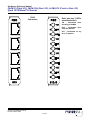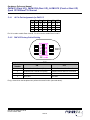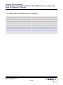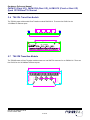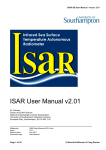
1
Hardware Reference Manual PMC610 (Front I/O), PMC610J4 (Rear I/O) & PMC612 (Front or Rear I/O) Quad 10/100BaseTX Ethernet DDC No. Rx-URMH 013 Rev B Issued 11 March 2002 Hardware Reference Manual PMC610 (Front I/O), PMC610J4 (Rear I/O), & PMC612 (Front or Rear I/O) Quad 10/100BaseTX Ethernet This page intentionally left blank. DDC No. Rx-URMH 013 Rev B Issued 11 March 2002 2 of 22 Hardware Reference Manual PMC610 (Front I/O), PMC610J4 (Rear I/O), & PMC612 (Front or Rear I/O) Quad 10/100BaseTX Ethernet Notice The information contained in this manual has been carefully reviewed and is believed to be entirely accurate. However, RAMiX shall not be liable for errors contained herein. Users are encouraged to recommend improvements for future revisions. RAMiX reserves all rights to make changes to improve reliability, function or design without notice. Customer Support To obtain quick technical support, use our email hot-link: [email protected]. Corporate Headquarters RAMiX Inc. 1672 Donlon Street, Ventura, CA 93003, USA Tel: 1+805-650-2111 • Fax: 1+805-650-2110 http://www.gefanuc.com/embedded RAMiX Europe Ltd. 3/2 Great Michael House, 14 Links Place Edinburgh EH6 7EZ, United Kingdom Tel: +44 131 561-3520 • Fax: +44 131 561-3521 Copyright 2005 RAMiX Inc. All rights reserved. No part of this document may be reproduced, by any means, without the prior written consent of the copyright holder. Reproduction without written consent constitutes infringement under the Copyright Law of the United States. DDC No. Rx-URMH 013 Rev B Issued 11 March 2002 3 of 22 Hardware Reference Manual PMC610 (Front I/O), PMC610J4 (Rear I/O), & PMC612 (Front or Rear I/O) Quad 10/100BaseTX Ethernet 1 Introduction This manual describes operation, configuration and installation instructions for the RAMiX, PMC610/PMC610J4 and PMC612 Quad Ethernet PMC controllers. All are Quad Port Ethernet interface cards, offering four, fully independent 10/100 Mbit Ethernet ports using Twisted Pair media (10/ 100BaseTx). Designed to be plugged onto a host processor (e.g., Single Board Computer (SBC)) card, the product family provides an extremely compact, economical high performance Ethernet solution. The PMC610J4 differs from the PMC610 in the method of connection to the network. The PMC610 has four standard R4J5 connectors accessed on the front panel of the module. The PMC610J4 uses the common mezzanine card (CMC) connector to route the network signals to the host card (which will generally connect to uncommitted pins on the backplane). Use of this connection method complies with industry standards; the specific pin designations are specific to the PMC610J4 (see Specifications for pin out detail). The PMC612 combines the I/O routing of both the PMC610 and PMC610J4. Routing (front panel or rear) is selected by switches on the card, or signal to the J4 connector (allowing routing based upon the presence/absence of a transition card). There is no operational difference between the products. In the rest of this document, except were explicitly noted, references to the PMC610 apply to all models. The PIM610J4 is designed to give rear access Input/Output (I/O) when used in conjunction with RAMiX's PIM610J4. The PIM module mates to rear transition modules, which have been designed to the PIM standard (see section on the PIM610J4 for detail) The PIM612 is designed to give rear access Input/Output (I/O) when used in conjunction with RAMiX's PIM612. The PIM module mates to rear transition modules, which have been designed to the PIM standard (see section on the PIM612 for detail) 1.1 Features The PMC610 complies with the CMC specification for Peripheral Component Interconnect (PCI) Mezzanine Cards (commonly known as PMC). As such, it will directly connect to any SBC or Expansion Card that supports PMC modules. All initialization, and functional configuration of the PMC610 is done automatically by software. Features implemented on the PMC610 include: • Four, independent 10/100Mbit Ethernet controllers • Auto-negotiation to determine speed and duplex • Full duplex operation is supported • Automatic power up configuration per PCI specification • High performance linked list direct memory access (DMA) engine for efficient PCI use • Deep first-in/first-out (FIFO) buffers on both Transmit and Receive data paths DDC No. Rx-URMH 013 Rev B Issued 11 March 2002 4 of 22 Hardware Reference Manual PMC610 (Front I/O), PMC610J4 (Rear I/O), & PMC612 (Front or Rear I/O) Quad 10/100BaseTX Ethernet 2 Handling And Installation 2.1 Handling Precautions Electronic assemblies use devices that are sensitive to static discharge. Observe anti-static procedures when handling these boards. All products should be in an anti-static plastic bag or conductive foam for storage or shipment. Work at an approved anti-static workstation when unpacking boards. 2.2 Unpacking And Verification RAMiX products are shipped in individual, reusable shipping boxes. When receiving the shipping container, inspect it for any evidence of physical damage. If the container is damaged, request that the carrier’s agent be present during the unpacking of individual boxes and the inspection of each unit. Remove the PMC module from the shipping box and anti-static packaging. Verify that it is not damaged and that all items are present by referring to the packing list. 2.3 Installation The PMC module is now ready for installation. Installation is done generically as with the commercial versions of the card. Follow any specific procedures recommended by the manufacturer of the chassis used. Turn all system power OFF. Remove the host board from the chassis (if currently installed). Locate the PMC connectors on the host board. Carefully plug the PMC module into the mating connectors on the host’s printed circuit board. Be sure the PMC module is seated properly into the common mezzanine card (CMC) connectors on the host. Refer to the following page. DDC No. Rx-URMH 013 Rev B Issued 11 March 2002 5 of 22 Hardware Reference Manual PMC610 (Front I/O), PMC610J4 (Rear I/O), & PMC612 (Front or Rear I/O) Quad 10/100BaseTX Ethernet Use screws to fasten PMC card t the host CMC. • Remove the four screws from bottom of the stand-offs of the PMC. • Line-up the J1 and J2 connectors on the host CMC to the J1 and J2 connectors on the PMC card. (For PMC610J4 the J4 connector will also be installed and must be mated). • Ensure all connectors are properly aligned before pushing the connectors together. • Use the four screws to connect the PMC stand-offs to the host CMC. 1. Remove the four screws from bottom of the stand-offs of the PMC610. 2. Line-up the J1 and J2 on the host PCB to PMC610, J1 & J2. (For PMC610J4 the J4 connector will also be installed and must be mated). 3. Push the PMC610 down (make sure all connectors are positioned properly). 4. Use the four screws to connect the PMC610 stand offs to the host PCB. DDC No. Rx-URMH 013 Rev B Issued 11 March 2002 6 of 22 Hardware Reference Manual PMC610 (Front I/O), PMC610J4 (Rear I/O), & PMC612 (Front or Rear I/O) Quad 10/100BaseTX Ethernet 2.4 Connection To The Local Network Media 2.4.1 PMC610 The PMC610 has four RJ45 style connectors on the front panel. These allow direct connection using industry standard cabling. 2.4.2 PMC610J4 The PMC610J4 routes all signals to the “J4” connector. This connector is a fully defined option in the industry standard (CMC) specification of the PMC module. It will mate with any host card that has provision for this option. In general, the host card will extend the signals to reserved pins on the backplane (e.g., rows A&C of VME bus). 2.4.3 PMC612 The PMC612 has both the front panel RJ45 connectors of the PMC610 and signals routed to the J4 connector. Only one of the two is active at a given time. (Controlled by switch position or signal indicating presence of transition module) 2.5 Front Panel Connectors And Indicators 2.5.1 PMC610J4 Panels There are no LED indicators on the PMC610 The PMC610J4 has three indicators for each port: • 100 - illuminated when link speed is 100Mbit • ACT - illuminates when activity (Rx or Tx) is present on the port • LINK - Illuminated when a good Link is detected from the partner Port numbers 0-3 are identified on each front panel. DDC No. Rx-URMH 013 Rev B Issued 11 March 2002 7 of 22 Hardware Reference Manual PMC610 (Front I/O), PMC610J4 (Rear I/O), & PMC612 (Front or Rear I/O) Quad 10/100BaseTX Ethernet RJ45 Connectors Each port has 3 LED’s associated with it. 100 – Illuminated when operating at 100Mbit LNK – Illuminated when valid link detected ACT – Illuminated on any Rx or Tx packets DDC No. Rx-URMH 013 Rev B Issued 11 March 2002 8 of 22 Hardware Reference Manual PMC610 (Front I/O), PMC610J4 (Rear I/O), & PMC612 (Front or Rear I/O) Quad 10/100BaseTX Ethernet 2.5.2 PMC612 Panel RJ45 Connectors LED Indicators one per Port Illuminate when valid link detected on the associated port DDC No. Rx-URMH 013 Rev B Issued 11 March 2002 9 of 22 Hardware Reference Manual PMC610 (Front I/O), PMC610J4 (Rear I/O), & PMC612 (Front or Rear I/O) Quad 10/100BaseTX Ethernet 3 PMC610 Architecture Host PCI PCI/PCI Bridge LLooccaall P PC CII B Buuss 10/100Mbit MAC 10/100Mbit MAC 10/100Mbit MAC 10/100Mbit MAC PHY PHY PHY PHY Isolation Magnet Isolation Magnet Isolation Magnet Isolation Magnet 3.1 PMC610 Subsystems The PMC610 architecture consists of a PCI/PCI bridge to comply with PCI loading specifications and four highperformance 10/100 Ethernet interfaces on a local PCI bus segment. 3.1.1 Bridge In order to ensure correct operation, the PCI Specification carefully limits the number of devices that can be directly attached to a PCI bus segment. To allow the inclusion of multiple devices within a single system, the PCI to PCI bridge was defined during the early definition of the specification. The bridge provides electrical isolation, creating a secondary bus segment that has a subsection of the PCI address space. Configuration of the bridge is fully defined in the PCI specification; it may be automatically set up by the low level BIOS or other initialization firmware. Once configured, any transaction on the host bus that is destined for an address on the secondary bus is captured by the bridge and forwarded on. The bridge has posting, and read-ahead features that allow full PCI bandwidth transfers to occur across it. DDC No. Rx-URMH 013 Rev B Issued 11 March 2002 10 of 22 Hardware Reference Manual PMC610 (Front I/O), PMC610J4 (Rear I/O), & PMC612 (Front or Rear I/O) Quad 10/100BaseTX Ethernet 3.1.2 Ethernet Controllers The Ethernet Controllers on the PCM610 have enjoyed several years of active evolution, featuring improvements at both the PCI bus, and Ethernet interface. Each controller is a fully independent unit, with local FIFO buffers to decouple PCI and Ethernet activity. Decoupling the Ethernet, and PCI ensures that data transfers will meet the timing requirements of each transaction (which is of particular importance on the Ethernet) regardless of the loading on the other bus interface. These FIFO buffers are sufficiently deep to support good burst transfers, and presenting minimum overhead to the PCI bus. When doing data transfer on the PCI bus the Ethernet DMA engine will attempt to maximize the length of burst transactions, which is critical to obtain the potential bandwidth of the PCI protocol. These properties allow sustained full bandwidth transfers on both Ethernet ports. The DMA engine supports linked list (scatter/gather) operation for support of “zero copy” software drivers. Each controller can operate at 10 or 100Mbit speeds in full or half duplex. When used in full duplex operation in a switched fabric environment very high transfer determinism can be achieved. Support for Auto Negotiation (IEEE 802.3u) allows dynamic configuration of speed and duplex operation based upon capabilities of the current attached device. Negotiation may be over-ridden via software to force a specific speed/duplex operating mode. DDC No. Rx-URMH 013 Rev B Issued 11 March 2002 11 of 22 Hardware Reference Manual PMC610 (Front I/O), PMC610J4 (Rear I/O), & PMC612 (Front or Rear I/O) Quad 10/100BaseTX Ethernet 4 PIM610J4 Module The PIM610J4 Module is a(n) (optional) PIM compliant card routing the Four Ethernet ports to RJ45 connectors. The PMC specification provides for user defined I/O to exit the PMC through one or more 64 pin connectors. This user I/O is commonly employed to bring I/O to the rear of the system in order to augment or replace the I/O available on the PMC’s bezel at the front. Prior to the PIM standard, a transition module could not be configured to integrate with an arbitrary PMC card (with J4 I/O routing). The PIM standard defines the mechanical and routing for a daughter card to be installed on a transition board. This allows for the manufacturer of a transition module to allow site-specific configuration of host card (e.g., Single Board Computer) with appropriate PMC modules. The diagram below illustrates the PIM card and connector. The RJ45 connectors are wired to the 10/100 Tx Specification. DDC No. Rx-URMH 013 Rev B Issued 11 March 2002 12 of 22 Hardware Reference Manual PMC610 (Front I/O), PMC610J4 (Rear I/O), & PMC612 (Front or Rear I/O) Quad 10/100BaseTX Ethernet 5 Functional Specifications 5.1 PMC610 Quad 10/100 BaseTX Ethernet, Front I/O Power 3 Watts @ 3.3 V 0.9 Amp Form Factor PMC Single Slot MTBF MIL 217-F Nav Shel 25 Deg. C 281000 Hours Temperature Operating 0 to +60° C Storage -40 to +85° C Humidity Operating 5% to 95% Non-Condensing Storage 5% to 95% Non-Condensing Conformal Coating Yes, additional charge PCI Bus Characteristics Signaling 3 & 5V Specification 2.2 Speed 33/66MHz Width 32 Ethernet Characteristics Ports 10/100 Base-TX 4 Port Routing Front RJ45 DDC No. Rx-URMH 013 Rev B Issued 11 March 2002 13 of 22 Hardware Reference Manual PMC610 (Front I/O), PMC610J4 (Rear I/O), & PMC612 (Front or Rear I/O) Quad 10/100BaseTX Ethernet 5.2 PMC610J4 Quad 10/100BaseTX PMC Ethernet, Rear I/O Power 3 Watts @ 3.3 V 0.9 Amp Form Factor PMC Single Slot MTBF MIL 217-F Nav Shel 25 Deg. C 281000 Hours Temperature Operating 0 to +60° C Storage -40 to +85° C Humidity Operating 5% to 95% Non-Condensing Storage 5% to 95% Non-Condensing Conformal Coating Yes, additional charge PCI Bus Characteristics Signaling 3 & 5V Specification 2.2 Speed 33/66MHz Width 32 Ethernet Characteristics Ports 10/100 Base-TX 4 Port Routing Rear routed to J4 Transition Module available DDC No. Rx-URMH 013 Rev B Issued 11 March 2002 14 of 22 Hardware Reference Manual PMC610 (Front I/O), PMC610J4 (Rear I/O), & PMC612 (Front or Rear I/O) Quad 10/100BaseTX Ethernet 5.2.1 PMC610J4 Pin Out Assignments The table identifies (by pin number) the location for the signals of each port on the J4 connector. Port A B C D Tx+ 6 14 22 30 Tx4 12 20 28 Rx+ 3 11 19 27 Rx1 9 17 25 CTR 2 10 18 26 CTT 5 13 21 29 In general, only the Tx/Rx pairs will be required (these are what comprise a standard 10/100BaseT cable or RJ45 connector). 5.3 PIM610J4 PIM Transition Module for PMC610J4 Power 0 Total Watts MTBF MIL 217-F Nav Shel 25 Deg. C 600000 Hours Temperature Operating 0 to +60° C Storage -40 to +85° C Humidity Operating 5% to 95% Non-Condensing Storage 5% to 95% Non-Condensing DDC No. Rx-URMH 013 Rev B Issued 11 March 2002 15 of 22 Hardware Reference Manual PMC610 (Front I/O), PMC610J4 (Rear I/O), & PMC612 (Front or Rear I/O) Quad 10/100BaseTX Ethernet 5.3.1 PIM610J4 Transition Module RJ 45 Connectors 0 0 1 1 2 2 3 3 PIM 610J4 DDC No. Rx-URMH 013 Rev B Issued 11 March 2002 16 of 22 Hardware Reference Manual PMC610 (Front I/O), PMC610J4 (Rear I/O), & PMC612 (Front or Rear I/O) Quad 10/100BaseTX Ethernet 5.4 PMC612 Quad 10/100BaseTX Ethernet Front or Rear I/O Power 3 Watts @ 3.3 V 0.9 Amp Form Factor PMC Single Slot MTBF MIL 217-F Nav Shel 25 Deg. C 281000 Hours Temperature Operating 0 to +60° C Storage -40 to +85° C Humidity Operating 5% to 95% Non-Condensing Storage 5% to 95% Non-Condensing Conformal Coating Yes, additional charge PCI Bus Characteristics Signaling 3 & 5V Specification 2.2 Speed 33/66MHz Width 32 Ethernet Characteristics Ports 10/100 Base-TX 4 Port Routing Front or Rear RJ45 Transition Module available DDC No. Rx-URMH 013 Rev B Issued 11 March 2002 17 of 22 Hardware Reference Manual PMC610 (Front I/O), PMC610J4 (Rear I/O), & PMC612 (Front or Rear I/O) Quad 10/100BaseTX Ethernet 5.4.1 J4 Pin Out Assignments for PMC612 Port A B C D Tx+ 6 14 22 30 Tx4 12 20 28 Rx+ 3 11 19 27 Rx1 9 17 25 CTR 2 10 18 26 CTT 5 13 21 29 Pin 16 is used to enable Ports A and B. Pin 24 is used to enable Ports C and D 5.4.2 PMC612 Factory Switch Setting 1 2 3 4 SW1 ON SW1 Switch Number ON OFF 1 Enables Port A and B to J4 (Rear) Enables Ports A and B to Front Panel 2 Enables Ports C and D to J4 (Rear) Enables Ports C and D to Front Panel 3 Not Used Not Used 4 Not Used Not Used Pin(s) 16 and 24 on the backplane can perform the same function (as noted above). DDC No. Rx-URMH 013 Rev B Issued 11 March 2002 18 of 22 Hardware Reference Manual PMC610 (Front I/O), PMC610J4 (Rear I/O), & PMC612 (Front or Rear I/O) Quad 10/100BaseTX Ethernet 5.5 PIM612 PIM Transition Module for PMC612 Power 0 Total Watts MTBF MIL 217-F Nav Shel 25 Deg. C 600000 Hours Temperature Operating 0 to +60° C Storage -40 to +85° C Humidity Operating 5% to 95% Non-Condensing Storage 5% to 95% Non-Condensing DDC No. Rx-URMH 013 Rev B Issued 11 March 2002 19 of 22 Hardware Reference Manual PMC610 (Front I/O), PMC610J4 (Rear I/O), & PMC612 (Front or Rear I/O) Quad 10/100BaseTX Ethernet 5.5.1 PIM612 Transition Module RJ45 Connectors 3 3 2 2 1 1 0 0 PIM 612 DDC No. Rx-URMH 013 Rev B Issued 11 March 2002 20 of 22 Hardware Reference Manual PMC610 (Front I/O), PMC610J4 (Rear I/O), & PMC612 (Front or Rear I/O) Quad 10/100BaseTX Ethernet 5.6 TR610A Transition Module The TR610A mates to Motorola's Rear Transition module PMC610J4. There are four RJ45's for the 10/100BaseTX Ethernet ports. J1 TR610A MADEIN U.S.A. PN 14-0880B00 J4 5.7 TR610B Transition Module The TR610B mates to Rear Transition module mates to a rear VME P2 connector for our PMC610J4. There are four RJ45's for the 10/100BaseTX Ethernet ports. Z3 2 Z1 DDC No. Rx-URMH 013 Rev B Issued 11 March 2002 21 of 22 MA DE I N U.S .A . PN 7 008 9 0 REV .A T R6 10B J2 Corporate Headquarters RAMiX Inc 1672 Donlon Street, Ventura, CA 93003, USA Tel: 1+805-650-2111 • Fax: 1+805-650-2110 RAMiX Europe Limited 3/2 Great Michael House, 14 Links Place Edinburgh EH6 7EZ, United Kingdom Tel: +44 131 561-3520 • Fax: +44 131 561-3521