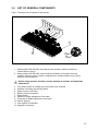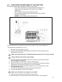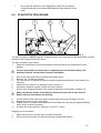
1
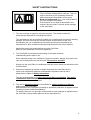
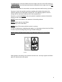
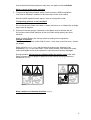
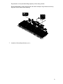
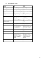
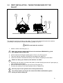
User Manual and
Parts Book of the
Verti-Rake
4500-6000
Serial number:
Translation of the original operating instructions
ATTENTION:
IT IS OF THE UTMOST IMPORTANCE TO READ THIS USER MANUAL
CAREFULLY PRIOR TO USING THE VERTI-RAKE IN ORDER TO USE THE
MACHINE SAFELY AND TO OBTAIN THE BEST RESULTS.
0948 English 961.120.202
FOREWORD
Congratulations on your Verti-Rake purchase! For safe and long-lasting operation of this
Verti-Rake, it is necessary to read and to understand this user manual.
It is impossible to work safely with this machine without complete knowledge of its content.
The Verti-Rake is not a machine that works independently. It is the user’s responsibility to
use the correct tractor. The user must also check the tractor/Verti-Rake combination on
safety aspects such as noise level, user instructions and risk analysis.
The following pages deal initially with the general safety instructions. Every user should know
these safety instructions and apply them. At the end of this page, a registration card is
inserted. This registration card should be returned to enable us to deal with potential future
claims.
This user manual lists many instructions that are numbered in sequence. You should follow
this sequence. A
is an indication of a safety instruction. A
means a tip and/or note.
All information and technical specifications provided at the moment that this document is
published are the most recent ones. Design specifications may be changed without prior
notice.
This document is a translation of the original operating instructions.
Upon request, the original operating instructions are available in Dutch.
WARRANTY CONDITIONS
WITH DELIVERY THIS VERTI-RAKE IS GUARANTEED AGAINST MATERIAL DEFECTS.
THIS WARRANTY IS VALID FOR A PERIOD OF 12 MONTHS FROM THE PURCHASE
DATE.
VERTI-RAKE WARRANTIES ARE SUBJECT TO THE ‘GENERAL CONDITIONS FOR
SUPPLY OF PLANT AND MACHINERY FOR EXPORT, NUMBER 188’ THAT ARE
PUBLISHED UNDER THE AUSPICES OF THE UNITED NATIONS ECONOMIC
COMMISSION FOR EUROPE.
REGISTRATION CARD
For your own information, fill in the table below:
Serial number machine
Dealer name
Date of purchase
Remarks
2
SAFETY INSTRUCTIONS
Figure 1
The Verti-Rake is designed for safe use. This can
only be achieved if you completely follow the
safety instructions described in this manual.
Read and understand (Figure 1) the manual before
you start using the Verti-Rake.
If the machine is not used as described in this
manual, this can result in injuries and/or damage
to the Verti-Rake.
1. The user must be an expert in using the machine. The machine should be
professionally adjusted for cultivating the subsoil.
The manufacturer will not accept any liability for unprofessional use and its resulting
damage. All risks occurring with this are entirely at the expense of the user.
Not following the use, maintenance and repair instructions prescribed by the
manufacturer is also considered improper/unprofessional use of this machine.
Inspect the area to be treated before using the Verti-Rake.
Remove loose obstacles and avoid irregularities.
2. The Verti-Rake is manufactured according to the latest technical
understanding and is safe to use.
When careless people use, maintain or repair the machine, danger of injuries to the
user and to third parties can be the result. This must be avoided!
Always use the Verti-Rake in combination with the correct tractor as described in the
technical data.
3. All persons assigned to operate, maintain and repair the Verti-Rake by the
owner must completely read and understand the operation manual and in
particular the chapter of Safety Instructions.
The user is responsible for a safe Tractor/Verti-Rake combination. This entire
combination must be tested on noise, safety, risk and user friendliness. User
instructions should also be drafted.
4. The user is obliged to check the Verti-Rake for visible damage and defects
before using the Verti-Rake.
Modifications to the Verti-Rake (including its operations) that have a negative impact
on safety must be rectified immediately.
For safety reasons it is in principle not permitted to make changes or adjustments to
the Verti-Rake (except those approved by the manufacturer).
3
If modifications to the Verti-Rake have been made, then the current CE marking is
cancelled. The person that has made these modifications has to apply for a new CE
marking himself.
Check the Verti-Rake for loose bolts, nuts and components before every operation.
If present, check the hydraulic pipelines regularly and replace these when the
hydraulic pipelines are damaged or appear old. The replacing pipelines should
comply with the technical requirements of the manufacturer.
If present, you should always make the hydraulic installation pressure-free before
working on this installation.
NEVER use the Verti-Rake in the absence of the safety stickers.
NEVER crawl under the Verti-Rake.
If necessary, tilt the Verti-Rake.
NEVER step off the tractor while the motor is running.
In case of maintenance, adjusting and repairs, it is necessary to block the Verti-Rake
in order to prevent sinking away, driving off and/or sliding off.
Always switch off the tractor motor and take the tractor’s key out off the
ignition in case of maintenance, adjusting and repairs (Figure 2).
Figure 2
With regards to the safety of the machine and the user, use only original Verti-Rake
parts for maintenance and repairs.
4
Only authorised technical personnel may carry out repairs to the Verti-Rake.
Keep a record of the repair activities.
5. The general applicable health & safety (Dutch acronym: ARBO) regulations
must also be followed in addition to the instructions in this user manual.
Relevant traffic regulations also apply in case of using public roads.
Transporting persons is not permitted!
Do not use the Verti-Rake in the dark, in heavy rain/storm or on slopes with an angle
larger than 20 degrees.
6. All persons that are going to operate the Verti-Rake must be familiar with all
the functions and control elements of the Verti-Rake before starting any work
activities.
Attach the Verti-Rake to the towing vehicle according to the regulations.
(Danger of injuries!)
Check whether you have a clear field of vision – both close by and far away – before
you depart.
Safety stickers (Figure 2, 3 and 4) with an identical meaning are attached to the
sideboards (Figure 5) of the Verti-Rake. These safety stickers must always be clearly
visible and legible and must be replaced in case they have become damaged.
During operation, NO persons are allowed within the danger zone of the VertiRake, because there is danger of physical injuries caused by flying particles or
substances (Figure 3).
Figure 4
Figure 3
Keep a distance of minimum 4 metres
(Figure 4)!
5
Pay attention to the permitted lifting capacity of the towing vehicle.
Dress appropriately. Wear sturdy shoes with steel toecaps, long trousers and tie up
long hair. Do not wear loose clothing.
Figure 5
7. Location of the safety stickers (Figure 5)
6
TABLE OF CONTENTS
FOREWORD ..............................................................................................................2
WARRANTY CONDITIONS........................................................................................2
REGISTRATION CARD .............................................................................................2
SAFETY INSTRUCTIONS ..........................................................................................3
1.0
TECHNICAL DATA ....................................................................................................8
2.0
FIRST INSTALLATION – TAKING THE MACHINE OFF THE PALLET.....................9
3.0
LIST OF GENERAL COMPONENTS .......................................................................10
4.0
ATTACHING THE MACHINE TO THE TRACTOR ...................................................11
5.0
SETTING THE OPERATIONAL AGGRESSIVENESS .............................................12
6.0
TRANSPORTING THE VERTI-RAKE ......................................................................12
7.0
DRIVING SPEED......................................................................................................12
8.0
USING THE VERTI-RAKE........................................................................................12
9.0
START/STOP PROCEDURE ...................................................................................13
10.0
DETACHING THE VERTI-RAKE..............................................................................14
11.0
TROUBLE SHOOTING (PROBLEM ANALYSIS).....................................................15
12.0
EU DECLARATION..................................................................................................15
13.0
MAINTENANCE .......................................................................................................15
14.0
CHANGING THE SPRING PINS ..............................................................................16
15.0
OPTIONAL: BRUSH SECTION................................................................................17
7
1.0
TECHNICAL DATA
Model
4500
6000
Working width
4.5 m (177.2”)
6 m (236”)
Working depth
Surface processing
Surface processing
Speed
Maximum 12 km/h (7.5
mph)
550 kg (1213 lbs)
Maximum 12 km/h (7.5
mph)
675 kg (1488 lbs)
30 HP with minimum
lifting capacity of 650 kg
(1433 lbs)
1 sincle acting valve
54000 m2/h (58125 ft2/h)
30 HP with minimum
lifting capacity of 800 kg
(1763.7 lbs)
Distance between pins
15 mm (0.6”)
15 mm (0.6”)
Transport dimensions
LxWxH
1810x2800x1850 mm
71.3”x102.5”x72.8”
LxWxH
1810x2995x2600 mm
71.7” x 118” x 102.4”
Three-point connection
Cat. 1-2
Cat. 1-2
Grease
EP 2
EP 2
Standard components
Running wheels
adjustable in height
Verti-Rake pin section
Toolbox including a
manual
Running wheels
adjustable in height
Verti-Rake pin section
Toolbox including a
manual
Optional
Brush set
Brush set
Weight
Recommended tractor
Maximum capacity
(Theoretical at maximum speed
of 12 km/h [7.5mph])
72000 m2/h (7750001
ft2/h)
8
2.0
FIRST INSTALLATION – TAKING THE MACHINE OFF THE
PALLET
1
1
3
2
Figure 6
The machine is placed vertically on the pallet. To remove the pallet and to place the machine
horizontally on the ground, you take the following steps (see Figure 6):
NEVER crawl under the machine!
1. Attach a cable to the lifting eye (1).
Make sure that the cable/crane/lift can hoist minimum VR4500 825 kg (1819
lbs)/ VR6000 1000 kg 2205 LBS
2. Lift the machine including the pallet approx. 50 mm (2”) off the ground.
3. Take care that the machine is standing on the edge of the pallet (2).
4. Lower the machine controlled and calmly until it stands completely on the subsoil.
Watch out: Keep your distance; the machine can slide!
5. Dismantle the top rod pin (3) and let the pallet (2) rotate carefully around the 3-point pins (4)
until it stands on the subsoil.
6. Remove the bottom 3-point pins (4) and remove the pallet (2).
7. Connect the machine to the tractor (please refer to Chapter 4.0).
Use the proper tractor (please refer to the specifications).
Turn off the tractor and secure the tractor/Verti-Rake combination against
driving off and/or sliding off.
9
3.0
LIST OF GENERAL COMPONENTS
Figure 7 shows several important components:
1
2
4
3
12
11
5
6
4
2
7
10
8
9
Figure 7
1. Safety sticker 900.280.402; first read the user manual / toolbox including a
manual before using it.
2. Safety sticker 933.280.402; keep a minimum distance of 4 metres from the
machine. Stop the motor if repair or adjustment is needed. Watch out for flying
particles and substances!
All the safety stickers should be on the machine at all times and should be
understood.
3. The serial number is located at the front side of the machine.
4. Spindles for setting the working depth
5. Upper 3-point connection
6. Bottom 3-point connection
7. Rake section
8. Handle for angle adjustment of the teeth
9. Fixing pin for angle adjustment of the teeth
10. jack for parking
11. Lock system for transport
12. Hydraulic connection
10
4.0
ATTACHING THE MACHINE TO THE TRACTOR
Checking procedure before starting to attach the Verti-Rake.
− Check the Verti-Rake for visually discernable damage and
repair this if safe operation of the machine is no longer
guaranteed.
− Check whether all the nuts and bolts are tight.
− Check whether all safety stickers are present on the machine
and are not damaged.
NEVER use the machine without these items.
Figure 8
The Verti-Rake can be attached to the tractor by means of the 3-point attachment.
The procedure is as follows (see Figure 8):
1. Remove the 3-point pins (1 and 2).
2. Drive the tractor carefully backwards so that the lower connecting arms can
be attached to the frame.
Make sure that the tractor is blocked well and cannot move on its own accord!
Switch off the tractor before descending!
3. Connect the lower connecting arms to the 3-point pins (2) and secure these
with the supplied locking pins.
4. Set the stabilizer of the tractor to 100 mm lateral stroke.
5. Mount the top rod of your tractor and turn it outward until it reaches the same
height as the 3-point stop connection (3) of the Verti-Rake.
6. Connect the top rod (3) to the frame with the pin (1); secure the pin (1) with
the supplied locking pin.
7. Turn the top rod (3) inwards so that it becomes pressurized.
8. Connect the hydraulic hose 4 to the tractor
Make sure that all the securing pins are locked!
9. Start the tractor and lift the Verti-Rake off the subsoil.
10. Move the jack 5 in the top position and lock this with pin 6 and springpin 7
11
5.0
SETTING THE OPERATIONAL AGGRESSIVENESS
The aggressiveness can be set in two ways:
1. Adjusting the running wheels by turning the spindles (4) (Figure 7) at the front side of
the machine:
Set both sides of the machine at the same height so that it is possible to process the
field as evenly as possible.
2. Adjusting the angle of the pins:
Remove the locking pin and fixing pin (9). Adjust the angle of the teeth by moving the
handle (8) forwards or backwards. Subsequently, place the fixing pin and secure this
with the locking pin.
NEVER adjust the machine in such a way that it could damage the subsoil or the machine.
IMPORTANT! First check the working depth on the subsoil statically before using
the machine!
6.0
TRANSPORTING THE VERTI-RAKE
The user is responsible for transporting the Verti-Rake in back of the tractor over public
roads. Verify the national legislation regarding the regulations.
On open fields while the machine is raised, the maximum permitted speed is 12 km/h (7.5
mph) due to the weight of the Verti-Rake.
A higher speed can be dangerous for the driver and/or the public and can even damage the
machine.
When the machine is raised off the ground, the front axle of the tractor has to
support minimum 20% of its weight.
Always fold the machine before transporting
7.0
DRIVING SPEED
The driving speed is limited to 12 km/h (7.5mph).
It is NOT recommended to drive faster due to the fact that excessive wear & tear and
damage can occur to the machine and to the subsoil.
8.0
USING THE VERTI-RAKE
Before using the Verti-Rake in a location, you should check the following items:
1.
2.
3.
4.
5.
6.
Are there loose objects in the field? First remove these objects.
Are there slopes? The maximum slope is 20 degrees for the VertiRake.
Always go from top to bottom.
Is there danger of flying objects (e.g., golf balls) that distract the attention of the
driver? If so, the Verti-Rake CANNOT be used.
Is there danger of sinking/sliding away? If so, postpone the processing
until conditions improve.
A field can be worked several times in the same or different directions
in order to obtain better processing.
Do not make sharp bends and preferably, drive in straight lines;
otherwise you might damage the machine and the subsoil.
12
7.
9.0
Do not set the machine in a too aggressive mode; this can lead to
undesired damage of the subsoil and additional wear and tear of the
teeth.
START/STOP PROCEDURE
1
2
3
fig 10
The start procedure is VERY important. If this procedure is not executed as described below, serious
damage to the subsoil could be the result.
The start procedure is as follows:
1.
Check the Verti-Rake for loose components and look whether all components function
properly.
If loose components are observed or components do not function properly, the
problems must be solved before using the Verti-Rake!
2.
3.
4.
5.
6.
7.
Drive to the spot where the processing should take place.
Remove pin 1 of the lock system
Turn the top rod (3) inwards so that the machine stands perpendicular to the subsoil (see
Figure 8).
Unlock the lock system 2 by pulling the rope 3 see fig 10
Activate the hydraulic system to lower the outer sections.
Set the level of aggressiveness of the machine statically as described in Chapter 5.0.
Make sure that the tractor is blocked well and cannot move on its own accord!
Switch off the tractor before descending!
8.
9.
10.
11.
Let the machine drop until the machine hovers above the ground at approx. 50 mm.
Engage the tractor in the correct gear.
Set the tractor in forward motion and let the Verti-Rake sink onto the pre-adjusted bearing
rollers with a smooth movement.
Increase the driving speed to maximum 12 km/h (7.5 mph).
Stopping occurs as follows:
1.
2.
While driving, lift the machine with a smooth movement.
Drive to the next location and start the operation as described above.
13
10.0 DETACHING THE VERTI-RAKE
Figure 11
The machine can be detached from the tractor in the following manner (See Figure 11):
1. Drive the Verti-Rake to a parking area with a firm/flat surface.
Make sure that the tractor is blocked well and cannot move on its own accord!
Switch off the tractor before descending!
2.
3.
4.
5.
6.
7.
8.
Slide stamp 4 down and secure with pin 5 and lock pin 6.
Carefully drop the Verti-Rake to the subsoil.
Lock hydraulic system with pin 1 (see fig 10)
Disconect hydraulic hose 4 of the tractor
Release the top rod (3).
Take the locking pin out of the pin (1) and pull the pin out of the top rod connection.
Pull the locking pins out of the pins (2) and remove the pins.
Make sure that the Verti-Rake stands stable and cannot roll away and/or slide off!
9. Start the tractor and drive off.
14
11.0 TROUBLE SHOOTING (PROBLEM ANALYSIS)
Problem
Too little cleaning
Possible cause
Solution
Working depth is adjusted too Adjust the machine to more depth
shallow
Subsoil is too hard
Teeth are not sufficiently
aggressive
Sloppy image of the field after Machine is adjusted too
processing
aggressively
Subsoil is too wet
Drive along a few more steps
while adjusting to more depth
every time
Set the machine to a more
aggressive angle
Adjust the machine to a mode
that is less aggressive
Wait for better conditions
12.0 EU DECLARATION
We – Redexim BV, Utrechtseweg 127, 3702 AC Zeist, Holland – declare entirely under our
own responsibility that the product
VERTI-RAKE with a machine number as indicated on the machine and indicated in this
manual
to which this declaration relates is according to the stipulation of the 2006/42/EC directive for
machines.
Zeist, 01/10/09
A.C. Bos
Manager Operations & Logistics
Redexim Holland
13.0 MAINTENANCE
Time schedule
Check/Grease point
Method
Before every use
Check for loose bolts/nuts
Tighten loose bolts/nuts with
the correct tightening moment
Check hydraulic system
If needed repair
Presence and readability of the
safety stickers (Please refer to Figure
Replace these if not present or
damaged
5)
15
14.0 CHANGING THE SPRING PINS
1
2
Figure 12
A rake is mounted on the Verti-Rake. This rake consists of a tube frame equipped with spring
pins.
Depending on the use of the machine, wear & tear or breaking of the spring pins can occur.
This might mean that you will have to replace the spring pins at a certain point.
Replacing the spring pins is done as follows (see Figure 12):
Make sure that the Verti-Rake is blocked well and cannot move on its own
accord!
1.
2.
3.
Loosen bolt(s) and nut(s) (1) a single turn.
Remove the spring pin(s) (2) replace these with new ones.
Tighten bolt(s) and nut(s) (1).
16
15.0 OPTIONAL: BRUSH SECTION
The Verti-Rake is also available with an optional brush section (Figure 13).
A brush section can be mounted on the machine instead of the rake section.
Figure 13
17