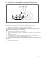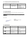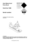
1
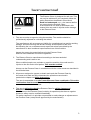
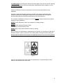
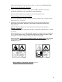
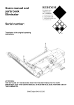
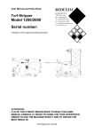
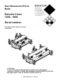
User Manual and Parts Book Extreme Clean 1200 - 1800 Serial number: Translation of the original operating instructions ATTENTION: IT IS OF THE UTMOST IMPORTANCE TO READ THIS USER MANUAL CAREFULLY PRIOR TO USING THE EXTREME CLEAN IN ORDER TO USE THE MACHINE SAFELY AND TO OBTAIN THE BEST RESULTS. 0948 English 142.120.000 FOREWORD Congratulation on your Extreme Clean purchase! For safe and long-lasting operation of the Extreme Clean, it is necessary to read and to understand this user manual. It is impossible to work safely with this machine without complete knowledge of its content. The Extreme Clean is not a machine that works independently. It is the user’s responsibility to use the correct tractor. The user must also check the tractor/Extreme Clean combination on safety aspects such as noise level, user instructions and risk analysis. The following pages deal initially with the general safety instructions. Every user should know these safety instructions and apply them. At the end of this page, a registration card is inserted. This registration card should be returned to enable us to deal with potential future claims. This user manual lists many instructions that are numbered in sequence. You should follow this sequence. A is an indication of a safety instruction. A means a tip and/or note. All information and technical specifications provided at the moment that this document is published are the most recent ones. Design specifications may be changed without prior notice. This document is a translation of the original operating instructions. Upon request, the original operating instructions are available in Dutch. WARRANTY CONDITIONS AT THE TIME OF DELIVERY THE EXTREME CLEAN IS GUARANTEED AGAINST MATERIAL DEFECTS. THIS WARRANTY IS VALID FOR A PERIOD OF 12 MONTHS FROM THE PURCHASE DATE. EXTREME CLEAN WARRANTIES ARE SUBJECT TO THE ‘GENERAL CONDITIONS FOR SUPPLY OF PLANT AND MACHINERY FOR EXPORT, NUMBER 188’ THAT ARE PUBLISHED UNDER THE AUSPICES OF THE UNITED NATIONS ECONOMIC COMMISSION FOR EUROPE. REGISTRATION CARD For your own information, fill in the table below: Serial number of the machine Dealer name Date of purchase Remarks 2 !SAFETY INSTRUCTIONS! Figure 1 The Extreme Clean is designed for safe use. This can only be achieved if you completely follow the safety instructions described in this manual. Read and understand (Figure 1) the manual before you start using the Extreme Clean. If the machine is not used as described in this manual, this can result in injuries and/or damage to the Extreme Clean. 1. The user must be an expert in using the machine. The machine should be professionally adjusted for cultivating the subsoil. The manufacturer will not accept any liability for unprofessional use and its resulting damage. All risks occurring with this are entirely at the expense of the user. Not following the use, maintenance and repair instructions prescribed by the manufacturer is also considered unprofessional use of this machine. Inspect the area to be treated before using the Extreme Clean. Remove loose obstacles and avoid irregularities. 2. The Extreme Clean is manufactured according to the latest technical understanding and is safe to use. When unskilled people use, maintain or repair the machine, this could result in injuries to the user and to third parties. This must be avoided! Always use the Extreme Clean in combination with the correct tractor as described in the technical data. 3. All persons assigned to operate, maintain and repair the Extreme Clean by the owner must read and fully understand the operation manual and in particular the chapter on Safety Instructions. The user is responsible for a safe Tractor/Extreme Clean combination. This entire combination must be tested for noise, safety, risk and user friendliness. User instructions should also be drafted. 4. The user is obliged to check the Extreme Clean for visible damage and defects before using it. Modifications to the Extreme Clean (including its operations) that have a negative impact on safety must be rectified immediately. For safety reasons it is in principle not permitted to make changes or adjustments to the Extreme Clean (except those approved by the manufacturer). 3 If modifications to the Extreme Clean have been made, then the current CE marking is cancelled. The person that has made these modifications has to apply for a new CE marking himself. Check the Extreme Clean for loose bolts, nuts and components before every operation. If present, check the hydraulic pipelines regularly and replace these when the hydraulic pipelines are damaged or appear old. The pipelines that are replaced should comply with the technical requirements of the manufacturer. If a hydraulic installation is present, you should always make it pressure-free before working on this installation. NEVER use the Extreme Clean in the absence of safety stickers. NEVER crawl under the Extreme Clean. If necessary, tilt the Extreme Clean. NEVER step off the tractor while the motor is running. When carrying out maintenance, adjustments and repairs, it is necessary to block the Extreme Clean in order to prevent it from sinking away, driving off and/or sliding off. Always switch off the tractor motor and take the tractor’s key out of the ignition in carrying out maintenance, adjustments and repairs (Figure 2). Figure 2 Use only original Extreme Clean parts for maintenance or repairs because of the safety of the machine and of the user. 4 Only authorised technical personnel may carry out repairs to the Extreme Clean. Keep a record of the repair activities. 5. The general applicable health & safety (Dutch: ARBO) regulations must also be followed in addition to the instructions in this user manual. Relevant traffic regulations also apply in case of using public roads. Transporting persons is not permitted! Do not use the Extreme Clean in the dark, in heavy rain/storm or on slopes with an angle larger than 20 degrees. 6. All persons who will be operating the Extreme Clean must be familiar with all the functions and control elements of the Extreme Clean before starting any work activities. Attach the Extreme Clean to the towing vehicle according to the regulations. (Danger of injuries!) Check whether you have a clear field of vision – both close by and far away – before you depart. Safety stickers (Figure 2, 3 and 4) with identical intentions are attached to the sideboards (Figure 5) of the Extreme Clean. These safety stickers must always be clearly visible and legible and must be replaced if they have become damaged. During operation, NO persons are allowed within the danger zone of the Extreme Clean, because there is danger of physical injuries caused by flying particles or substances (Figure 3). Figure 3 Figure 4 Keep a distance of minimum 4 metres! (Figure 2) 4) 5 Pay attention to the permitted lifting capacity of the towing vehicle. Dress appropriately. Wear sturdy shoes with steel toecaps, long trousers and tie up long hair. Do not wear loose clothing. Figure 5 (7) Location of the safety stickers (Figure 5) 6 TABLE OF CONTENTS WARRANTY CONDITIONS ....................................................................................... 2 REGISTRATION CARD ............................................................................................. 2 !SAFETY INSTRUCTIONS! ..................................................................................... 3 1.0 TECHNICAL DATA ......................................................................................... 8 2.0 FIRST INSTALLATION – TAKING THE MACHINE OFF THE PALLET......... 9 3.0 THE POWER TAKE-OFF (PTO) ....................................................................10 3.1 LENGTH OF THE PTO...................................................................................10 3.2 USE OF THE PTO............................................................................................11 3.2 SLIP COUPLING INFORMATION AND MAINTENANCE..............................11 4.0 LIST OF GENERAL COMPONENTS .............................................................12 5.0 ATTACHING THE MACHINE TO THE TRACTOR ........................................13 6.0 ADJUSTING THE FORCEFULNESS OF THE MACHINE .............................14 7.0 TRANSPORTING THE EXTREME CLEAN ...................................................14 8.0 DRIVING SPEED............................................................................................14 9.0 OPERATING THE EXTREME CLEAN...........................................................14 10.0 START/STOP PROCEDURE .........................................................................15 11.0 DETACHING THE EXTREME CLEAN FROM THE TRACTOR.....................16 12.0 TROUBLE SHOOTING (PROBLEM ANALYSIS) ..........................................17 13.0 EU DECLARATION........................................................................................17 14.0 MAINTENANCE .............................................................................................17 7 1.0 TECHNICAL DATA Model 1200 1800 Working width 1.20 m (47”) 1.80 m (71”) Working depth Adjustable Adjustable Speed Maximum 12 km/h (7.5 mph) 226 kg (498 lbs) Maximum 12 km/h (7.5 mph) 302 kg (666 lbs) Weight Recommended tractor 18 HP with minimum lifting 18 HP with minimum lifting capacity of 400 kg capacity of 300 kg (882 lbs) (662 lbs) Maximum capacity 9906 m2/h (106627 ft2/h) 14742 m2/h (158681 ft2/h) Transport dimensions LxWxH 1300 x 810 x 1,402 mm 51.2” x 31.9” x 55.2” LxWxH 1900 x 810 x 1,402 mm 74.8” x 31.9” x 55.2” Three-point connection Cat. 1-2 Cat. 1-2 Grease EP 2 EP 2 Standard components Brush unit Toolbox including a manual. PTO shaft Brush unit Toolbox including a manual. PTO shaft (Theoretical at maximum speed of 12 km/h [7.5mph]) 8 2.0 FIRST INSTALLATION – TAKING THE MACHINE OFF THE PALLET 1 2 3 4 Figure 6 The machine is placed vertically on the pallet. To remove the pallet and to place the machine horizontally on the ground, you take the following steps (see Figure 6): !! NEVER CRAWL UNDER THE MACHINE! 1. Attach a cable to the lifting eye (1). Make sure that the cable/crane/lift can hoist minimum 400 kg (882 lbs). 2. Lift the machine including the pallet of approx. 50 mm (2”) off the ground. 3. Make sure that the machine is standing on the edge of the pallet (2). 4. Lower the machine controlled and calmly until it stands completely on the ground. !! Careful: Keep your distance; the machine can slide! 5. Dismantle the top rod pin (3) and let the pallet (2) rotate carefully around the 3-point pins (4) until it stands on the ground. 6. Remove the bottom 3-point pins (4) and remove the pallet (2). 7. Connect the machine to the tractor (please refer to Chapter 4.0). Use the proper tractor (please refer to the specifications). Turn off the tractor and secure the tractor/Extreme Clean combination against driving off and/or sliding off. 9 3.0 THE POWER TAKE-OFF (PTO) The PTO is a very important component. It takes care of the drive of the tractor and of a safe use of the machine, provided it is installed and maintained in the correct manner. The PTO has its own CE certification. Read the PTO manual. This manual is located on the PTO. Figure 10 3.1 LENGTH OF THE PTO The length of the PTO is very important. If it is too long, it can damage the drive of the tractor and/or the Extreme Clean. If the overlapping length of the cylinders becomes less than 150 mm (6”) at any time, it can damage the PTO. The length changes when the machine is lifted or when a different tractor is used! In order to set the PTO on the correct length, when a new one has been purchased or when a different tractor is used, follow these steps: (see Figure 10) 1. Measure the distance between the PTO’s connection to the tractor and to the Extreme Clean, from groove to groove, when the machine is connected to the tractor and positioned on the ground at the right angle. 2. Measure the distance B of the PTO in its shortest position from the locking pin to the locking bolt. 3. Divide the PTO in two parts and remove the protection cap at both ends. 4. The ends of the cylinders and the ends of the protection caps must be made shorter: (B-A) + 75 mm (3”). 5. Smooth off all components, use some grease, and then assemble all components. 6. Mount the PTO on the side of the Extreme Clean. 7. Attach the other end of the PTO to the tractor. 8. Check the overlap of the cylinders. *Never use the machine if it has a damaged PTO protection cap. First remove any damaged parts. 10 3.2 USE OF THE PTO The following items must be checked for correct use of the PTO: 1. While working the angle of the pivot pins may not exceed 30 degrees. 2. The pivot pins must always be aligned. 3. The overlap of the cylinders must always be minimum 150 mm. 4. Never use the machine if it has a damaged PTO protection cap. 5. For lubrication see section 13.0: Maintenance. 3.2 SLIP COUPLING INFORMATION AND MAINTENANCE If used and maintained correctly, the slip coupling will protect your machine against damage. The following items are important: 1. The length of the spring is standard set at 33 mm (1.300”) 2. Whenever the slip coupling slips, the bolts/nuts can be tightened a quarter of a turn until you achieve a minimum length of 31.5 mm (1.250”) of the spring. Additional compression will overload the machine. Screwing the bolts/nuts too tight could ultimately damage the machine or create unsafe situations. 3. The slip coupling must be maintained on a monthly basis. Follow the following steps: - Disconnect the top PTO protection cap from the machine. Loosen up all the bolts/nuts by 2 turns. On the field let the machine run at very low revs. If the coupling slips, stop the motor after 10 seconds. If the coupling does not slip, loosen up the bolts further or proceed with the maintenance / annual maintenance task (see point 4 below). As soon as the coupling has slipped, screw the bolts/nuts tight until you see that the slip coupling is once again functioning properly. * Do not turn it back again to the previous setting. 4. Annual maintenance: - Disconnect the PTO from the machine. - Inspect all the components of the PTO. - All the damaged components should be replaced. - Take the slip coupling apart by removing all the bolts and nuts that fasten the springs to each other; the slip coupling should then simply fall apart. - Lay down all the components and look at them meticulously. If components are damaged or worn out, replace them. - Clean all interlocking components. - Re-assemble all the components and tighten the bolts and nuts so that the springs are adjusted to 33 mm (1.3”). - Grease both cylinders and reassemble both PTO parts. - Assemble the PTO and mount it on the machine. - In needed, brush the springs of the slip coupling as described below. @ If adjusted properly, the slip coupling protects the machine only against momentary overload. Long-term overload will damage the machine, In such cases the slip coupling cannot protect the machine. Do not overload your machine. 11 4.0 LIST OF GENERAL COMPONENTS Figure 7 shows several important components: 4 6 3 8 5 2 1 7 Fig. 7 1. 2. Safety sticker 900.280.402; first read the user manual / toolbox including a manual before using it. Safety sticker 933.280.402; keep a minimum distance of 4 metres from the machine. Stop the motor if repair or adjustment is needed. Watch out for flying particles! All the safety stickers should be on the machine at all times and should be understood. 3. 4. 5. 6. 7. 8. The serial number is located at the front side of the machine. Adjustment for setting the working depth Upper 3-point connection Bottom 3-point connection Brush section PTO sticker for indicating the turning direction and revs 12 5.0 ATTACHING THE MACHINE TO THE TRACTOR Checking procedure before starting to attach the Extreme Clean: Check the Extreme Clean for visually discernable damage and repair this if safe operation of the machine is no longer guaranteed. Check whether all the nuts and bolts are tight. Check whether all safety stickers are present on the machine and are not damaged. NEVER use the machine without these items. 1 2 3 Figure 8 The Extreme Clean can be attached to the tractor by means of the 3-point attachment. The procedure is as follows (Figure 8): 1. Remove the 3-point pins (1) and locking pins (2). 2. Drive the tractor carefully backwards so that the lower connecting arms can be attached to the frame. !! Make sure that the tractor is blocked well and cannot move on its own accord! !! Switch off the tractor before descending! 3. Connect the lower connecting arms to the 3-point pins (2) and secure these with the supplied locking pins. 4. Set the stabilizer of the tractor to 100 mm lateral stroke. 5. Mount the top rod of your tractor and turn it outward until it reaches the same height as the 3-point stop connection of the Extreme Clean. 6. Connect the top rod (3) to the frame with the pin (1); secure the pin (1) with the supplied locking pin. 7. Turn the top rod (3) inwards so that it becomes pressurized. . !! Make sure that all the securing pins are locked! 8. Start the tractor and lift the Extreme Clean off the ground. 13 6.0 ADJUSTING THE FORCEFULNESS OF THE MACHINE The forcefulness can be adjusted in the following ways: (See Figure 7) Adjusting the runners by changing the rings at the top and bottom Set both sides of the machine at the same height so that it is possible to treat the field as evenly as possible. NEVER adjust the machine in such a way that it could damage the subsoil or the machine. ! IMPORTANT! First check the working depth on the subsoil statically before using the machine! 7.0 TRANSPORTING THE EXTREME CLEAN The user is responsible for transporting the Extreme Clean in back of the tractor on public roads. Verify the national legislation regarding the regulations. On open fields while the machine is raised, the maximum permitted speed is 12 km/h (7.5 mph) due to the weight of the Extreme Clean. A higher speed can be dangerous for the driver and/or the public and can even damage the machine. When the machine is raised off the ground, the front axle of the tractor has to support minimum 20% of its weight. 8.0 DRIVING SPEED The driving speed is limited to 12 km/h (7.5mph). It is NOT recommended to drive faster due to the fact that excessive wear & tear and damage can occur to the machine and to the subsoil. 9.0 OPERATING THE EXTREME CLEAN Before using the Extreme Clean in a location, you should check the following items: 1. 2. 3. Are there loose objects in the field? First remove these objects. Are there slopes? The maximum slope is 20 degrees for this machine. Is there danger of flying objects (e.g., balls) that distract the attention of the driver? If so, the Extreme Clean CANNOT be used. 4. Is there danger of sinking/sliding away? If so, postpone the processing until conditions improve. A field can be worked several times in the same or different directions in order to obtain better processing. 5. 6. 7. Do not make sharp bends and preferably, drive in straight lines; otherwise you might damage the machine and the subsoil. Do not adjust the machine to work forcefully; this might result in damaging the subsoil and additional wear and tear of the brushes. 14 10.0 START/STOP PROCEDURE The start procedure is VERY important. If this procedure is not executed as described below, it might result in serious damage to the subsoil. The start procedure is as follows: 1. Check the Extreme Clean for loose components and look whether all components function properly. !! If loose components are observed or components do not function properly, the problems must be solved before using the Extreme Clean! 2. Drive to the spot where the processing should take place. !! Make sure that the tractor is blocked well and cannot move on its own accord! !! Switch off the tractor before descending! 3. 4. 5. 6. 7. 8. Allow the machine to sink until it is standing with the wheels on the ground. Adjust the forcefulness as discussed in chapter 5. Adjust the tractor engine to around 1200 rpm. Connect/mount the PTO and increase the PTO revs to the maximum permitted level. Engage the tractor in the correct gear. Shift the tractor to a forward movement and adjust the speed to the maximum of 12 km/h (7.5 mph). Stopping occurs as follows: 1. 2. 3. 4. 5. Let the tractor come to a standstill. Decrease the engine revs to 1200 rpm. Disconnect the PTO. Lift the machine. Drive to the next location and start the operation as described above. 15 11.0 DETACHING THE EXTREME CLEAN FROM THE TRACTOR 1 2 3 Figure 9 The machine can be detached from the tractor in the following manner (See Figure 9): 1. Drive the Extreme Clean to a parking area with a firm/flat surface. !! Make sure that the tractor is blocked well and cannot move on its own accord! !! Switch off the tractor before descending! 2. Carefully lower the Extreme Clean to the ground. 3. Adjust the height so that the machine is standing only on its wheels and not on the brush hairs. 4. Release the top rod (3). 5. Take the locking pin out of the pin (1) and pull the pin out of the top rod connection. 6. Pull the locking pins out of the pins (2) and remove the levers. !! Make sure that the Extreme Clean stands stable and cannot roll away and/or slide off! 7. Start the tractor and drive off. 16 12.0 TROUBLE SHOOTING (PROBLEM ANALYSIS) Problem Too little decompaction Possible cause - Working depth is adjusted too shallow Subsoil is too hard Solution - Adjust the machine to more depth Drive slower Adjust the working depth to less depth and continue to work again. 13.0 EU DECLARATION We – Redexim BV, Utrechtseweg 127, 3702 AC Zeist, Holland – declare entirely under our own responsibility that the product EXTREME CLEAN WITH MACHINE NUMBER AS INDICATED ON THE MACHINE AND IN THIS MANUAL, to which this declaration relates is according to the stipulation of the 2006/42/EC directive for machines. Zeist, 01/10/09 A.C. Bos Manager Operations & Logistics Redexim Holland 14.0 MAINTENANCE Time schedule Check/Grease point Method Before every use Check for loose bolts/nuts Tighten loose bolts/nuts with the correct tightening moment Presence and readability of the safety stickers (Please refer to Figure Replace these if not present or damaged 5) After every 50 working hours or annually After every 500 working hours Grease the bearings Use EP2 grease Grease the chain Silicone spray Change the oil of the gearbox SAE 90 17