1
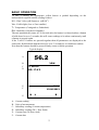
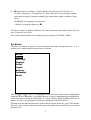
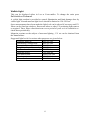
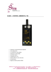
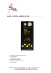
765 ENVIRONMENTAL MONITOR
USER MANUAL
LITTLEMORE SCIENTIFIC ENGINEERING (ELSEC)
Gutchpool Farm
Gillingham
Dorset
UK
Tel:
(+44) (0)1747 835550
Fax: (+44) (0)1747 835552
Email: [email protected]
765.docx
V1.5
CONTENTS
INTRODUCTION ...............................................................................................1
BASIC OPERATION ..........................................................................................2
Set Button ......................................................................................................3
UNITS OF MEASUREMENT .............................................................................5
Ultra-Violet (UV).............................................................................................5
Visible Light ...................................................................................................6
Temperature ..................................................................................................7
Humidity .........................................................................................................7
DISPLAY............................................................................................................8
Brightness ......................................................................................................8
CLOCK ..............................................................................................................9
Setting the Time.............................................................................................9
Setting the Date .............................................................................................9
Date Format ...................................................................................................9
Hiding the Clock.............................................................................................9
DATA LOGGING .............................................................................................10
Show Status.................................................................................................10
Start Logging ...............................................................................................10
Stop Logging................................................................................................10
Format .........................................................................................................10
Erase ...........................................................................................................10
Data Storage and Download .......................................................................11
Viewing the Results using RView ................................................................12
Manual Installation of older versions of RView ............................................13
Data Format .................................................................................................14
Batteries...........................................................................................................15
Non Standard Batteries ...............................................................................15
Charger ........................................................................................................15
Charging ......................................................................................................16
Battery Life...................................................................................................16
CALIBRATION .................................................................................................17
Humidity .......................................................................................................17
Temperature ................................................................................................17
UV & Visible Light ........................................................................................18
MAINTENANCE...............................................................................................19
Long term storage........................................................................................19
SERVICE AND SUPPORT ..........................................................................19
SPECIFICATIONS ...........................................................................................20
PRINTED 16-Dec-11
INTRODUCTION
One of the primary responsibilities of the custodian of artworks and museum artefacts
is to preserve them for future generations. How they are stored and displayed is
central to this, the 765 Environmental Monitor is an easy to use tool to help in
achieving the safest long term protection.
For many years it has been recognised that one of the major causes of damage to
museum objects and other antiquities is the fading and rotting effect of light on the
object. The most damaging part of the illumination is its ultraviolet (UV) content.
Using the 765 measurements can be taken of the proportion of UV present as
microwatts per lumen (mW/lumen), the total amount of UV as milliwatts per square
meter (mW/M2) and the amount of visible light present (Lux).
Most objects are also sensitive to humidity and temperature. The 765 also measures
humidity as % relative humidity and temperature as °C or °F.
The 765C logging version can be left for extended periods to log the above parameters
at a user set interval (10 seconds to 1 hour). The saved data can then be transferred to
a computer for display, graphing etc.
We always want to improve our products. If you have any suggestions please send
them to us.
1
BASIC OPERATION
To take a reading the appropriate yellow button is pushed depending on the
measurement required and the reading is taken.
UV= Ultra Violet (µW/lumen or mW/M2 )
Vis= Visible light (Lux or Foot-candles)
T= Temperature (Centigrade or Fahrenheit)
RH= Humidity (%Relative Humidity)
The unit automatically turns off 20 seconds after the button is released unless a button
is held down for over 3 seconds, this will cause readings to be taken continuously until
a button is pressed again.
If the T and UV buttons are pressed together then all parameters are displayed at the
same time. Hold both the buttons down for over 3 seconds for a continuous readout.
Note that the buttons should be pressed firmly ensure reliable operation.
Typical display:
56.2
A
%RH
B
C
D
T: 26.4°C
DP: 17.0°C
13:10
15-06-2012
E
F
G
A:
B:
C:
D:
E:
F:
H
L
B
Current reading
Units of measurement
Subsidiary reading (Current temperature)
Subsidiary reading (DP = Dew Point)
Current time (24 hour clock)
Current date
2
G: H shows that the reading is “Held” and the unit will turn itself off after 10
seconds of inactivity. A round blob “●” shows the unit is in continuous reading
mode until a button is pushed, nothing here means that a single reading is being
taken.
The L indicates logging is in operation.
A battery level gauge appears at B.
The above format is slightly different for some parameters and can be altered by the
user if required, see below.
The current time and date can be hidden by pressing Set\Clock\Hide-Unhide.
Set Button
The blue Set button is used to access advanced functions, change units etc. If it is
pushed once a menu similar to that below is shown:
MENU
Show>
Data log>
Display>
Units>
Clock>
Battery>
Calibrate>
About
The first menu item “Show” is highlighted, different menu items can be highlighted
using the é and ê buttons. The wanted action is done by highlighting the appropriate
menu item and pressing the Set button. To abort without doing anything press the X
button. In some cases a further sub-menu is displayed with more choices.
Elsewhere in this manual directions in the form Set\item1\item2 are given. This means
Press Set, select item1 in the first menu, press Set again, select item2 in the next menu
and press Set.
3
To take a measurement without having to look at the display while the reading is
taken (for example where the operators head may effect the reading) proceed as
follows:
1. Position the monitor where the reading is to be taken.
2. Push the appropriate button for 1-2 seconds and release.
3. Hold the monitor in position for at least 2 seconds.
4. Without operating any buttons by mistake move the monitor so the reading
can be noted before it turns itself off.
4
UNITS OF MEASUREMENT
Ultra-Violet (UV)
Traditionally UV has been measured in museums as the proportion of ultraviolet
present. This result is useful for checking a particular lamp or window because the
proportion of UV does not change rapidly with the distance from the light source.
Using a simple rule the amount of UV on an object can be limited. It is usual to
arrange that the proportion of UV should not exceed 75µW/lumen in museums and
galleries, though some organisations try to keep UV levels below 25µW/lumen
The damage is done by the total amount of UV falling on the object so it is useful to
be able to measure this directly, especially if non standard amounts of illumination are
required. The amount of UV should be as little as possible but in general should not
exceed 20mW/M2, again some organisations keep the level below 6mW/M2.
Both the above units are displayed when the UV button is pressed, one in large
characters, the other smaller at the bottom of the screen. Which is displayed where can
be swapped by pressing Set\Units\µW/Lumn-mW/M².
When measuring low levels of UV the 765 can take up to 5 seconds to take the
reading. So, to get a reasonably quick response, when initially turned on, the unit only
measures for one second and if UV levels are low this will show as zero. If the "UV"
button is pushed again the full 5 seconds is allowed for the measurement and if a low
level of UV is present it will be detected and displayed.
5
Visible Light
This can be displayed either in Lux or Foot-candles. To change the units press
Set\Units\Lux-Footcandl.
A visible light readout is provided to control illumination and limit damage done by
visible light. Normal museum light levels should be limited to 150-250 Lux.
Once measurements have been made the light level can be altered if necessary and UV
filters can be fitted on windows, fluorescent tubes or other UV producing light sources
as required. These filters often deteriorate over a period of years so it is essential to recheck them periodically.
Magazine reprints on the subject of museum lighting , UV etc can be obtained from
the manufacturer.
Suggested light levels for various other purposes are given below:
Corridor, stairs etc
100/150 Lux
Warehouses, storage bays
100/150 Lux
General office work
300/500 Lux
Rough bench/machine work
300/500 Lux
Medium bench/machine work 500/700 Lux
Drawing offices
750/1000 lux
Fine bench work
1000/1500 Lux
Fine inspection
1500/3000 Lux
Minute work
3000/5000 Lux
6
Temperature
Temperature can be measured in degrees Centigrade or Fahrenheit. To change the
units press Set\Units\Temperature.
Humidity
Humidity is measured as % relative humidity (%RH). This is the fraction of the
maximum amount of water that the air can hold at the current temperature and
pressure.
In general if the temperature is reduced the amount of water it can hold gets less. So if
the temperature of some air is reduced its humidity rises, and at some point the air will
not be able to hold the water it has and water will start to condense out (form
mist/cloud or drops of water on a surface), the relative humidity has reached 100%.
The temperature at which this happens is the dewpoint. The 765 displays the dewpoint
with the humidity.
The temperature/dewpoint difference is often used as a measure of the likelihood of
condensation (fog) occurring, particularly in meteorology. If the temperature is only
one or two degrees above the dewpoint in the evening then fog is likely as the
temperature falls during the night.
The UK National Trust tries to keep the indoor relative humidity between 50% and
65%, aiming for 58%.
7
DISPLAY
Brightness
As supplied the 765 automatically adjusts the display brightness to suit the ambient
light level. For a fixed brightness press Set\Display\Manual and select a brightness
level between 0 (dim) and 127 (bright) before pressing Set.
To make the display brightness automatic again press Set\Display\Auto
The display uses a large amount of battery power, the brighter it is the quicker the
batteries run down.
8
CLOCK
The 765 has a built in clock, this is used for Data Logging
Setting the Time
To set the time proceed as follows, the procedure can be abandoned at any time by
pressing the X button:
1.
Press Set\Clock\Set time. The display shows the current time with the hours
highlighted.
2.
Use é and ê buttons to adjust the hours to the correct value and press the
Set button.
3.
The minutes are now highlighted. Repeat 2 above to set the minutes. When
the set button is pressed the seconds are set to zero.
Setting the Date
To set the date proceed as follows, the procedure can be abandoned at any time by
pressing the X button:
1.
Press Set\Clock\Set date. The display shows the current date as Day-MonthYear with the day highlighted (note that the date is always shown in this
order regardless of the date format setting as described below).
2.
Use é and ê buttons to adjust the day to the correct value and press the Set
button.
3.
The month is now highlighted. Repeat 2 above to set the month.
4.
The year is now highlighted, repeat 2 above to set the year.
Date Format
The time and date are shown at the bottom of the display with every reading. The date
is normally displayed as day-month-year, this can be changed to the American format
(month-day-year) by pressing Set\Clock\DMY-MDY. The format can be restored to
day-month-year by repeating this.
Hiding the Clock
If the date and time are not needed they can be hidden by pressing
Set\Clock\Hide-Unhide. Repeat to unhide.
9
DATA LOGGING
Data logging is an optional extra. A standard unit can be upgraded to include data
logging by returning it to the manufacturer. If data logging is not fitted then the
relevant menu items are not displayed.
If data logging is fitted “Data log” is one of the options when the Set button is pushed.
Show Status
To see how much data has been saved, when logging was started etc select
Set\Data log\Status and the information is shown on the screen for 30 seconds. Press
the X button to clear the screen sooner.
Start Logging
To start logging press Set\Data log\Start and then select the log period and press Set
again. The unit turns off and logging starts at the beginning of the next minute, 10
minutes or hour as appropriate.
The Log Period is how often readings are taken, if the log period is short then it will
be less time until memory space runs out.
Logging commences at a time so that measurements are taken at the start of each
minute, 10 minutes, hour etc.
Every time logging is started a new file is created on the internal USB flash drive (see
below) with a name of the form MMddhhmm.CSV where:
MM=month
DD=day
hh=hour
mm=minute
The unit can be used while logging but there is a very small chance that this may
interfere with the logging function so it is recommended that use is restricted to
occasional status checks and charging.
Stop Logging
To stop logging press Set\Data log\Stop. This stops further readings being taken.
Format
This option on the “Data log” menu formats the internal flash drive (see below). This
causes all the files on the flash drive to be deleted.
Erase
The Erase option on the “Data log” menu completely erases all data on the flash drive
and then formats it. Not normally required.
10
Data Storage and Download
The logged data is stored in files on an internal USB flash drive or “USB data stick”.
When the unit is turned on and connected to a Microsoft Windows PC with the
supplied USB cable it will be recognised as a standard external disk drive. Depending
on the PC settings a window will appear asking what to do, it is suggested that the
“Open folder to view files” option is selected. If necessary go to “My computer” or
“Computer” on the start menu and the new drive should appear on the list where it can
be clicked to show any data logger files.
Once a list of logger files is displayed in Windows Explorer they can be dragged to
the PC desktop or any other folder in the normal way. When a logger file has been
transferred to the PC it should be deleted from the logger to free up space. This can be
done from Windows Explorer or by pressing Set\Data log\Format which deletes all
files on the flash drive.
Microsoft Windows XP, Vista and 7 should be able to use the logger without any
special drivers or other software. When the 765C is plugged in for the first time
Windows may say that it is searching for drivers, these should be found without
assistance.
The storage capacity is over 73,000 readings of all 4 parameters (UV, Visible light,
temperature and humidity). The other values (e.g. dewpoint and µW/Lumen) are
calculated from the 4 saved parameters.
Log Period
10 seconds
1 Minute
10 Minutes
1 Hour
Log time for 73,000 records
8+ Days
50+ Days
500+ Days (about 1 year, 4 Months)
Over 8 years
The storage capacity is shared between the data files. So leaving old data files on the
flash drive will limit the space available for new data.
Logging will continue until the memory is full or a low battery condition is detected.
When connected to the PC a “U” is displayed on screen to the left of the Clock.
When the internal flash disk is being read from or written to the LED left of the screen
flashes green.
Because the data is saved as text, the larger the data values, the more memory each
reading takes (for example “100000” has more characters than “1.1”). The maximum
space per set of 4 readings is 28 characters (usually it will be much less). The internal
flash memory has a capacity of 2,048,000 characters.
11
Viewing the Results using RView
For more detailed information on RView see the help file.
RView is a program that can be downloaded from the Littlemore Scientific web site,
www.elsec.com.
RView is not necessarily required since the data files can be viewed with any
spreadsheet (eg Microsoft Excel).
When RView is started an empty window is shown. One or more data files can be
opened by selecting File\Open on the menu or pressing the appropriate button on the
toolbar.
When a data file is opened the information is displayed as a graph in it’s own window.
More than one graph can be open at any time.
The graph can then be manipulated in the following ways:
Change the graphed parameters. If ‘Show’ is selected on the menu a list of
parameters that can be plotted is shown with the current selection ticked. The various
items can be ticked/unticked to change what is shown.
Make the graph bigger/smaller. Use the standard window controls on the top right
of the graph window and/or drag the edges of the graph as required.
Zoom to see part of the data in more detail. Move the mouse cursor to one corner
of the area of interest, click and hold the left mouse button while moving the mouse
cursor so that the area of interest has a box drawn round it. When the mouse button is
released the graph is redrawn showing only the selected area.
Change the temperature units. Select ‘Show’ on the menu and the current units are
shown (°C or °F) click on this to change the units.
Move the Legend. When the graph is first drawn the legend box may hide part of the
data. This can be moved by clicking on the box and dragging it to a new location. If it
changes to a free floating window it can be removed completely or put back on the
graph by clicking on it again.
Check the time/value of a point on the graph. Move the mouse cursor to the point
of interest, the time and value represented by the position is shown on a status bar at
the bottom of the window.
Add/Change the title of the graph. Press the Titles button on the toolbar and enter
the title as required.
Print the graph. Select File/Print on the menu.
Copy the Graph to the Clipboard. Select edit/copy on the menu or press the
appropriate button on the toolbar. The saved image can now be pasted into other
programs, documents etc.
12
Manual Installation of older versions of RView
RView version 3.8 will work with Windows Vista and Windows 7 but the installer is
not compatible. To install manually proceed as follows. Only do this for RView V3.8
on Windows Vista or 7 and if you understand computers – if you don’t then get
assistance):
1. Rename the installer file RView38.exe to RView38.zip
2. Create a folder “C:\Program Files\ELSEC\RView” or similar.
3. Open the RView.zip file by clicking on it.
4. Drag the files RVIEW.EXE and RVIEW.HLP from RView38.zip to the newly
created folder. Ignore any other files in RView38.zip
5. Create a shortcut to the new copy of RVIEW.EXE (one way is to right click on
it and select “send to” and “desktop”).
6. Drag the shortcut to the start menu.
13
Data Format
The data is saved as a CSV file (comma separated variable). This is a plain, human
readable text file, each record of Lux, UV, temperature and RH is on one line, each
value separated by a comma.
The .CSV files can be opened directly in any spreadsheet, eg Microsoft Excel.
The first line has column titles separated by commas and a fifth value giving
information about the log start time, period etc. This data will look similar to:
2014-10-12_1308_000010_0010901*AName****0000544771
YYYY-MM-DD_HHmm_hhmmss_rrrrrrr*NNNNNNNN*ssssssssss
YYYY-MM-DD = Log start date
HHmm = Log start time (hours and minutes, seconds always zero)
hhmmss = Log interval (hh=hours, mm=minutes, ss=seconds)
rrrrrrr = no of records in file
NNNNNNNN = Logger name, with extra * to make 8 characters
ssssssssss = Misc logger status values
14
Batteries
The 765 is designed to use 4 off AAA size NiMH rechargeable batteries. The
instrument is supplied with these fitted.
The supplied batteries should last for several years and hundreds of charge cycles.
The batteries can be replaced by removing the back cover from the instrument. Ensure
replacement batteries are fitted the correct way round. Always use a completely fresh
set, unused, all from the same packet.
We recommend the use of GP “Recyko” NiMH batteries. These have the advantage
that they will keep their charge for over a year if the instrument is not used unlike
other types that will go flat in a few weeks. There are other makes of NiMH that have
similar properties (eg Sanyo “eneloop”), but we have not tested these.
Non Standard Batteries
In an emergency any AAA size 1.2 – 2V battery can be used in the 765 with the
following limitations:
· If using non-rechargeable types (eg alkaline) NEVER try to charge the batteries.
To disable charging press Set\Battery\Never. Charging can be re-enabled by
pressing Set\Battery\Allowed.
· Do not mix different types of batteries in the instrument.
· Do not try to charge anything other than NiMH cells in the 765. This may cause
damage to the instrument and/or the batteries.
Charger
The 765 is supplied with an international charger. Before use the appropriate mains
plug need to be clipped onto it. As standard we supply a UK 13A plug, European 2
pin and USA 2pin. An Australian style plug is also available.
Any 5V USB charger/power supply can be used that is capable of supplying a current
of 0.6A.
The 765 can also be charged by plugging it into a PC USB port using the cable
supplied (or equivalent).
15
Charging
To charge the batteries plug the charger into the mains and connect to the instrument
using the USB cable supplied. Turn on the 765 by pressing any button briefly and
charging will start indicated by the red lamp to the left of the display.
The 765 needs to be on when charging starts but can be allowed to turn off while
charging continues.
When charging is complete the red lamp turns off.
Normal charge time for completely dead batteries is 3-4 hours.
The unit senses charging is complete by measuring the battery temperature. This can
be confused if the unit is moved from somewhere with a very different temperature to
the place where it is charged. If in doubt leave the 765 to warm up/cool down for 15
minutes before starting to charge.
Charging is only permitted between 0 and 40°C (32-104°F).
After charging completes further charging is not permitted until either:
· The unit is used for 5 hours.
· 5 Days have passed.
· The batteries are replaced.
· The time or date are changed by the user
The unit can be forced to start charging by pressing Set\Battery\Start
Battery Life
A fully charged set of batteries will typically power the 765 for:
·
·
·
·
·
20 hours at maximum display brightness (2,400 30 sec readings)
33 hours at normal display brightness (3,960 30 sec readings)
120,000 log readings spread over 1 month
50,000 log readings spread over 1 year
2 years switched off (maintaining clock only)
These values may be affected by very low or high temperatures
16
CALIBRATION
The calibration information is kept in non-volatile ROM. If this fails the instrument
displays “Mem Fail” when turned on and will load default calibration values and
future readings may be 25% in error. If this happens a question mark “?” is displayed
on the top right of the display with suspect readings.
Humidity
Like most other RH sensors the 765 should be checked every 6 months or a year. This
can be done by returning the unit to the manufacturer, by using the optional humidity
calibration kit or by comparison to another known good source.
The 765 is fitted with a solid state sensor that should not require recalibration unless it
is damaged by solvents, dirty water or atmospheric pollutants.
If the sensor is contaminated it can usually be reconditioned by the following
procedure:
1.
2.
3.
4.
5.
Remove the sensor from the instrument.
Bake the sensor at 100-105°C, less than 5% RH for 10 hours
Allow the sensor to cool naturally to room temperature.
Re-hydrate the sensor at 20-30°C and ~75%RH for 12 hours
Replace the sensor onto the 765 and re-check
Alternatively the sensor can be swapped for another, pre-tested one, from your
supplier.
Temperature
The 765 is fitted with a solid state temperature sensor that should not normally require
calibration. This sensor is part of the RH sensor and so can be replaced in the same
way as above.
17
UV & Visible Light
The 765 calibration should not drift with time but to be sure of accuracy the
instrument can be returned to the manufacturer for a calibration check every 2-5 years.
The 765 has a very carefully defined frequency response (i.e. which wavelengths of
light it is sensitive to). Other light meters are often more sensitive to infra red light
than they should be and so will give a higher reading with light sources that contain
infrared (e.g. ordinary filament light bulbs).
Because the 765 has a cosine angular response it may give different readings to a type
762 which is relatively directional. In other words the 765 is more sensitive to light
coming at an oblique angle than the 762.
Note that the human eye has a logarithmic response, this means that if two luxmeters
are placed side by side they may give different readings even if it looks like they are
getting a similar amount of light. To compare the readings on 2 meters they each need
to be placed in the exactly same position under exactly the same lighting conditions
with the operator being very careful not to shade the meters differently.
18
MAINTENANCE
The sensor windows should be kept clean and grease free. Grease and finger marks
that look clear may be opaque to UV. Ensure that solvents do not come into contact
with plastic parts, especially
lly the acrylic window over the visible (left-hand)
(left hand) sensor.
It is permissible to use a cloth dampened with clean water, ethanol, methylated spirits
or iso propyl alcohol (IPA) to clean the outside of the 765.
Keep all fluids and other contaminants away from
from the humidity sensor in the probe at
the top of the instrument.
Long term storage
If the instrument is to be stored unused for over a year the batteries should be
removed.
SERVICE AND SUPPORT
For support and repairs contact the manufacturer:
Littlemore Scientific Engineering
Gutchpool Farm
Gillingham
Dorset UK
SP8 5QP
Tel: 01747 835550
Fax: 01747 835552
Email: [email protected]
http://www.elsec.co.uk
This equipment complies with EU Directive 2002/96/EC
The symbol of the crossed container on the equipment
equipment shows that the product, at the
end of its useful life, must be collected separately from other refuse. When it is
disposed of in the European Union it should be placed with other electronic waste at
the place designated by the waste collection authority.
autho
19
SPECIFICATIONS
Method of radiation detection Twin silicon photodiodes connected to microprocessor.
Visible wavelength range
400-700nM (CIE response). No correction required for different
light sources.
Visible power range
0.1 - 200,000 Lux (0.1 – 20,000 Foot-candles)
UV wavelength range
300-400 nM
UV power range
UV proportion range
RH sensor
RH range
Display resolution
2 - 10,000 mW/M2
Accuracy
Light: 5% ±1 displayed digit
UV: 15% ±1 displayed digit
Temperature: ±0.5°C (±0.9°F)
RH: ±3.5% 10%-90%, otherwise ±5%
Angular response
Readout
Data logging time intervals
(Time till full)
Cosine (Light & UV)
128x64 OLED Display with automatic brightness control
10 seconds (8 days), 1 minute (50 days) , 10 minutes (500 days),
1 hour (8 years)
0 - 10,000 mW/Lumen
Capacititive film type
0-99%RH
Lux: 0.1 up to 100 then 1
Foot-candles: 0.1 up to 100 then 1
UV: 0.1 up to 100 then 1
Proportion of UV: 1 mW/Lumen
Temperature: 0.1°C or °F
RH: 0.1%
Data logging storage capacity Over 73,000 readings of all 4 parameters
Computer Interface
Built in USB flash drive
Batteries
4 off AAA NiMh rechargeable
Battery life
30 hours of normal use or 120,000 log readings
External charger
5-6V DC, 500mA USB
Operating Temperature
0-60°C
Operating Humidity
0-99%, non condensing
Dimensions
170 x 60 x 15mm 6.7 x 2.4 x 0.6 inches Including
RH/Temperature probe
240g (8.5 oz) with batteries.
Weight
20
21