1
SERVICE MANUAL
REFRIGERATING
© Electrolux
Muggenhofer Straße 135
D-90429 Nürnberg
Germany
Fax +49 (0)911 323 1022
Spares Operation
Ausgabe:
05.01
Publ.-Nr.:
599 51 15 61
685
DE
NO-FROST
CONTROLLER(S)
12/93 UNTIL MID-1997
(IN DEEP FREEZERS,
REFRIGERANT R134a)
Special FeaturesRefrigeration
292 5210 69
Equipment-Specific Part
10.
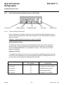
No-frost controllers, from date of manufacture 12/93
10.1
General
Technical modifications have been made on microprocessor controlled electronic
controllers (power board and logical board). New electronic units are identified by the
printed item numbers 675 125 933 and 675 125 934, which also are the part numbers. You
can moreover identify the power board 675 125 933 from the separate PE connecting plug
tag. On deep freezers with such electronic systems, the interference filter in the
compressor tagboard will no longer be applicable, since it is now directly mounted on top
of the electronic controller.
The paper below is focussing on the modifications, changed parameters being printed in
bold letters! Consult the previous description, if necessary.
Technical support: please note that, from now on, only the mentioned power and logic
boards will be available. So you should also consult Service Instructions 299 500 302 and
associated Information Sheets 290 800 002 and 290 800 004. It is important that an
interference filter is installed in the compressor tagboard, whenever the power board is not
provided with a PE connecting line!
10.2
Superfrost Function
By pressing the Superfrost button, the Superfrost function can both be activated and
deactivated.
Usually, the Superfrost function is automatically stopped at -32°C air temperature. In order
to avoid too short operation time with minor charging, the Superfrost function is stopped
after 30 hours only, at the earliest. If air temperature of -32°C is not reached, the electronic
controller stops the Superfrost function after 51 hours.
05.2001
-2-
599 51 15 61
DE
Special FeaturesRefrigeration
292 5210 70
Equipment-Specific Part
10.3
Determination of actual temperature to be displayed, visible on the LC display
In order to suppress during one control cycle, and especially during the defrosting phase, the
display of air temperature oscillation inside the deep freezer, actual temperature is averaged for
display.
On start-up, super mode and after door opening, the display shows the temperature detected by
the air temperature sensor. When reaching the preset nominal temperature, the latter will be
displayed. Any set point deviations within a bandwidth of +/-2K are suppressed. That is, the
displayed temperature will always be equal to the nominal value, so long as the actual
temperature is within such a bandwidth.
Averaging will be stopped after door openings, on super mode, after any air temperature
changes, and as soon as actual temperature passes beyond the defined bandwidth. In order to
avoid temperature steps in normal mode, air sensor temperature is displayed after two differing
retard periods only.
The 2 changing speeds are defined as follows:
during heating up:
temperature change within 12min by max. 1 K;
during cooling:
temperature change 1 min each per 1 K
Exception:
On battery mode, the displayed temperature equals the measured temperature plus a
correcting value of 1 K.
Averaging will be reactivated when set point and actual temperature are equivalent again (set
point = actual temperature).
05.2001
-3-
599 51 15 61
DE
Special FeaturesRefrigeration
292 5210 71
Equipment-Specific Part
10.4
Control and Information System (monitor; LED display)
+
Tool wrench
10.4.1
defrost warning
temperature alarm
door alarm
battery alarm
Function warning (tool wrench)
Like on the electronic controllers used up to now, this warning will be activated on sensor
failures, defrost-heating failures, faults in the refrigeration cycle, and defective temperature
selector switches.
Changes, compared with the previous no-frost controller
Defrost-heating failures
The electronic system recognizes defrost-heating failures by means of the evaporator
thermal sensor, comparing evaporator temperatures at the beginning of the defrosting
phase and 15 min afterwards. If no temperature increase > 10 K occurs, the function
warning is displayed.
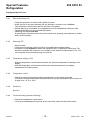
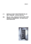
Diagnosis of Errors
To facilitate the diagnosis of errors, the occurring faults are classified by means of an error
code. Each code is displayed on the green temperature display (LC display) while the quit
key is pressed and the temperature setting button extended.
0RQLWRU/('GLVSOD\
05.2001
Tool wrench
7HPSHUDWXUH'LVSOD\
/&GLVSOD\
F1
Tool wrench
F2
Air temperature sensor defect
Tool wrench
F3
Refrigerator sensor defect
Tool wrench
F4
Heating system defect
Tool wrench
F5
Refrigeration cycle defect
-4-
&DXVHRI7URXEOHGHIHFWLYH
FRPSRQHQW
Temperature selector defect
599 51 15 61
DE
Special FeaturesRefrigeration
292 5210 72
Equipment-Specific Part
10.4.2
Defrost warning
Defrost warning responds, as soon as the air temperature is heated up to -2°C. This warning is
displayed both optically and acoustically. The highest temperature in the freezer is displayed
alternating with the actual temperature.
You can reset the defrost warning by using the quittance key (no automatic reset). After reset
with the quittance key, the highest temperature is no longer on display.
When starting up, the defrost warning is suppressed until display temperature is by 4 K higher
than the set point temperature.
10.4.3
Temperature alarm
Temperature alarm is activated, once the actual temperature is by 5 K higher than set point
temperature.
You can switch off the alarm by pressing the acknowledge key. Acoustic and optical temperature
warning are automatically reset, once the actual temperature is only 4 K higher than the set point
temperature (alarm off value).
After adjusting the set point temperature, the temperature warning is disabled, and release can
be activated only if the warning off value is reached, or if the actual temperature exceeds 10°C.
15 sec after starting up, an optical warning is displayed. However, if you bypass the self-test,
this will occur immediately!
The alarm signal will be suppressed until the warning off value is reached for the first time. In
Super mode, the alarm signal is blocked.
10.4.4
Door alarm
Opening the door directly activates door alarm message on the monitor. If the door remains
open for more than 80 sec, the alarm goes off. After closing the door, the door alarm is reset. It
is separately possible to switch the alarm off by using the acknowledge key. The door alarm
function is disabled during battery operation!
10.4.5
Battery alarm
The battery is checked 15 sec after starting up. However, when the self-test is bypassed, this
will occur immediately! Battery voltage check is done after every battery replacement, after every
mains failure, and prior to any defrosting cycle. If the battery voltage is too low, e.g. after 3 days
of battery mode, the battery alarm will be activated. No acoustic warning available!
05.2001
-5-
599 51 15 61
DE
Special FeaturesRefrigeration
292 5210 73
Equipment-Specific Part
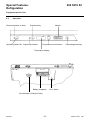
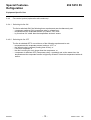
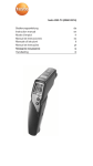
10.5
Connection diagram
R7
BN BK
Part No. 675 092 101
BU
M3
x3.5
x3.6
E1
BU
BN
R3
Q8
N
L
PE
H1
H2
BN
BU
BK
M2
C1
R2
x3.2
F2
x3.1
F3
x3.4
RD
R5
x3.3
BK
BU
Power board
R8
BN BK
AMP-Größe
2,8
4,8
Logic board
Connection diagram S 33
05.2001
-6-
599 51 15 61
DE
Special FeaturesRefrigeration
292 5210 74
Equipment-Specific Part
10.6
Connection diagram legend
C1
E1
F2
F3
G1
H1
H2
M2
M3
R2
R3
R5
R7
R8
Betriebskondensator
Kondensator
Lampe
Lamp
Klixon-Abtauheizung
Klixon ontdooiweerstand
Klixon-Flächenheizung
Klixon vlakweerstand
Batterie
Batterij
Signallampe grün
Lamp groen
Signallampe gelb
Lamp geel
Motorverdichter-Gefrieren
Kompressor (diepvries)
Lüfter-Gefrieren
Ventilator
Abtauheizung
Ontdooiweerstand
Anlauf-PTC-Gefrieren
PTC weerstand (diepvries)
Tauwasserheizung, Flächenheizung
Dooiwatergootverwarming
Gefrierteil-Verdampferfühler
Verdampervoeler-diepvriesgedeelte
Gefrierteil-Luftfühler
Luchtvoeler-diepvriesgedeelte
running capacitor
Condensateur
lamp
lampe
klixon defrost heater
Clixon rêsistance de degivrage
klixon surface heater
Clixon rêsistance plate
battery
Batterie
signal lamp green
Lampe verte
signal lamp yellow
Lampe jaune
motor condenser freezing
Compresseur (surgêlateur)
fan freezing
Ventilateur
defrost-heating
Rêsistance PTC (surgêlateur)
starting-PTC-freezing
Rêsistance PTC (surgêlateur)
defrost water heating, surface heating
Chauffage rigole eau dêgivrage
freezer evaporator sensor
Sonde air ambient-partie surgêlateur
freezer air sensor
Sonde air-partie surgêlateur
Farbdefinitionen - colour-definitions - Kleuren - Couleurs
bk ......
bn......
bu......
ye ......
gn......
rd ......
wh......
05.2001
black
brown
blue
yellow
green
red
white
schwarz
braun
blau
gelb
grün
rot
weiß
zwart
bruin
blauw
geel
groen
rood
wit
-7-
noir
brun
bleu
jaune
vert
rouge
blanc
599 51 15 61
DE
Special FeaturesRefrigeration
292 5210 51
All other functions are identical to the former series; sections enclosed to this document
9.
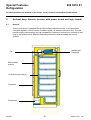
No-frost deep freezers (version with power board and logic board)
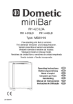
9.1
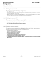
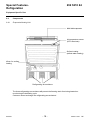
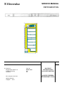
General
This no-frost series is equipped with an electronically controlled monitor; a microprocessor
controlled regulation, the no frost air circulation system, as well as a child-proof lock. The vital
benefits of this new technology are high temperature constancy in all levels, no formation of hairfrost on the freezing stock, automatic defrosting on demand, and the display and control
systems.
Multiple-disk
evaporator
Fan
Defrost water
channel
Air channel (rear interior)
Condenser
Compressor
05.2001
-8-
599 51 15 61
DE
Special FeaturesRefrigeration
292 5210 52
Equipment-Specific Part
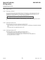
9.2
Operation
Green equipment-on lamp
Superfrost key
Monitor
o
Operating switch ON Superfrost indicator
C
Temperature control button
Acknowledgement key
Temperature display
Battery receptacle
Door switch
Circuit breaker (child-proof lock)
05.2001
-9-
599 51 15 61
DE
Special FeaturesRefrigeration
292 5210 53
Equipment-Specific Part
9.2.1
Start-up/Switching ON
-
9.2.2
Press the equipment-on switch until it clicks into place.
Within the first 3 min after switching ON, the electronic controller runs a self-test.
The compressor will start only after the self-test is completed.
Defrost warning is not enabled, is in preparation once the temperature warning is reset.
Temperature warning is only indicated by display.
Switching ON without self-test:
by pressing the Superfrost button and, at the same time, pressing the equipment-on switch,
until it clicks into place.
Switching OFF
- Open the door
- Press the circuit breaker (child-proof lock) for enabling the operating switch.
- Important! It is not possible to switch the equipment OFF by pulling the mains plug! The
electronic controller will continue to run in battery mode whenever mains power is cut. You
can recognize this by a warning beep every 20 sec.
9.2.3
Temperature display (LCD)
- With the temperature control button extended, the set point temperature is flashing on the
display.
- With the temperature control button pressed, the actual temperature is on display
(temperature of freezing stock).
9.2.4
Temperature control
- Setting the set point temperature with the temperature control button extended
- You can set the required set point temperature by turning the temperature control button in 1
K steps from -15°C to -24°C.
9.2.5
Superfrost
See 10.2
9.2.6
Forced defrosting (manual defrosting)
- Extend the temperature control button
- Press the acknowledgement key and, at the same time, press the Superfrost button.
05.2001
- 10 -
599 51 15 61
DE
Special FeaturesRefrigeration
292 5210 54
Equipment-Specific Part
9.3.3
Battery mode/warning on mains failure
The equipment automatically changes over to battery mode, if, for whatever reasons, no mains
voltage is applied. Control functions are maintained, but the compressor is not working!
- Immediately upon mains failure, an alarm is activated, emitting a signal every 20 sec.
- You can suppress the alarm for a period of 2 hrs by using the acknowledgement key. As a
substitute, optical warnings (monitor) will be flashing for a period of 10 sec.
- The green equipment-on lamp goes off.
- The actual temperature is indicated in the temperature display, but not backlit, so you cannot
read it.
9.4
Regulating and control functions
9.4.1
Fan control (explanation with logic symbols)
- Switching ON the fan:
&
Compressor ON
Evaporator temperature < -15°C
Fan ON
DT1 < -3 K
- Switching OFF the fan:
Compressor OFF
&
>1
DT1 >= 5 K
Fan OFF
Dt > 4 min
Door OPEN
Defrost ON
Evaporator temperature > -10°C
DT1 = Evaporator temperature - air temperature
Dt = after-run time of fan, compared with the compressor
In case of malfunction of the temperature sensor, the fan is switched jointly with the
compressor.
05.2001
- 11 -
599 51 15 61
DE
Special FeaturesRefrigeration
292 5210 55
Equipment-Specific Part
9.4.2
Fan control system (explanation with sentences)
9.2.4.1 Switching the fan ON
The fan is switched ON if the following three requirements are simultaneously met:
- compressor switched ON (compressor relay = voltage-free);
- temperature at the evaporator sensor (R7) below -15°C; and
- by more than 3 K colder than the temperature at the air sensor.
9.4.2.2 Switching the fan OFF
The fan is switched OFF if one minimum of the following requirements is met:
- temperature at the evaporator sensor is above -10°C; or
- the defrost cycle is reached (frosting time 60 hrs), or
- if the door is opened; or
- the fan is running for 4 min longer than the compressor; or
- compressor is switched OFF (compressor relay = operated) and, at the same time, the
temperature at the evaporator sensor is higher by at least 5 K than the temperature at the air
sensor.
05.2001
- 12 -
599 51 15 61
DE
Special FeaturesRefrigeration
292 5210 57
Equipment-Specific Part
9.4.4
Switching the compressor ON
The compressor is switched ON (relay = voltage-free), if
- the self-test is over,
- after expiring at least 5min after the compressor was switched off by the electronic controller
(minimum standstill = 5min), and
- at the same time, the current temperature at the air sensor (actual temperature) is by 0.67 K
minimum higher than the preset temperature (set point temperature).
9.4.4.2 Switching the compressor OFF
The compressor is switched OFF (relay = operated), if
- the current temperature at the air sensor is by 1 K minimum colder than the preset
temperature (set point temperature), or
- the defrosting cycle is reached, or
- the previously started Superfrost function is finished.
9.4.4.3 Permanent compressor operation
The appliances are provided with the so-called positive failure mode, that is, the compressor is
switched to permanent operation when the following faults occur:
- prohibited sensor resistances
(such as sensor short circuit, break), or
- when the defrost-heater is defect, or
- if the temperature setter is defect
(meaning that the logic board must be exchanged), or
- if malfunctions occur on the refrigeration cycle, or
- if the Superfrost function was selected; however, the Superfrost function is limited in time and
temperature.
05.2001
- 13 -
599 51 15 61
DE
Special FeaturesRefrigeration
292 5210 59
Equipment-Specific Part
9.4.6
Heater control
9.4.6.1 Defrosting on demand
Automatic defrosting takes place after 60 hours of frosting time, at the beginning of the next
standstill time of the compressor. If, after 65 hours, no standstill period has begun yet, the
compressor is switched off, in order to start a defrosting cycle.
Frosting time = compressor operating time + 180 x door opening time
The defrosting cycle will be ended 4 min after switching off the heaters. Frosting time is set to
0.
9.4.6.2 Switching the heaters ON
Defrosting heaters and surface heating are switched ON, if
- either defrosting on demand (after 60 hrs frosting time), or defrosting on demand is activated,
and
- at the same time, the evaporator sensor is OK.
9.4.6.3 Switching the heaters OFF
Defrosting heaters and surface heating are switched OFF, if
- the temperature at the evaporator sensor is higher than 7°C, or
- since the beginning of the defrosting cycle, more than 40 min have passed, or
- the evaporator sensor is in failure.
05.2001
- 14 -
599 51 15 61
DE
Special FeaturesRefrigeration
292 5210 61
Equipment-Specific Part
9.6
Self-test
Within the first 3 minutes after switching ON, the electronic system runs a self-test.
Order of sequence:
-
For 15 sec, all indicators are lit (power consumption approx. 9 mA*)
For 15 sec, pause
For 15 sec, the fan is switched on (power consumption approx. 30 mA*)
For 15 sec, pause
For 15 sec, the heaters are switched on (power consumption approx. 1.3 A*)
For 105 sec, pause
For 15 sec min., the compressor is switched on (power consumption > 0.5 A*)
*where UN = 230 V
9.7
Trouble-Shooting and Remedies
9.7.1
Malfunction with functional alarm activated (tool wrench)
Due to the intelligent control and display system, the following malfunctions are early recognized
and indicated:
- Sensor failure
- Defrost-heating failures
- Faults of the refrigeration cycle
- Failure of the temperature control button
9.7.2
Sensor failure
The electronic is capable of detecting any sensor failure where prohibited resistance values
occur. The table below shows the limit resistance values of evaporator and air temperature
sensors. You should refer to this table for fault finding by means of resistance measuring.
Temperature [°C]
Resistance kW
If the measured resistance values are equal to the values mentioned in the table, the fault can
only be located in the refrigeration cycle, the heaters or the temperature control button, that is,
the logic board.
05.2001
- 15 -
599 51 15 61
DE
Special FeaturesRefrigeration
292 5210 62
Equipment-Specific Part
9.7.4
Faults of the refrigeration cycle
The electronic system recognizes a malfunction in the refrigeration cycle by determining the
difference of temperature between evaporator and air temperature sensor.
Alarm message unless the evaporator temperature has not fallen below the air temperature by 3
K minimum within 15 min of switching on the compressor.
If the compressor operating time is < 15 min, then the problem check is interrupted.
9.7.5
Failure of the temperature control button
The electronic system signals a functional alarm when wrong resistance values of the
temperature control button are detected (100 kW) - potentiometer).
Examination is possible with ohmmeter directly on the logic board.
- 3 soldering points in the triangle
- between the two outer soldering points = 100 kW
- between the central taps and one outer tap, depending on the control button position, 0-100
kW.
If the measured values are not correct, replace the logic board!
9.8
Test aid
Problem
Cause and Remedy
- Evaporator in permanent mode,
temperature display colder than -25°C,
tool wrench lit
- Sensor, defrost-heater, temperature control
button defect, or malfunction of the
refrigeration cycle
- Fan only running during self-test, every
20 min the defrosting cycle is started,
insufficient refrigerating capacity, tool
wrench is not lit
- Light switch is not controlled or is defect.
- Peak power during cooling cycle (power
supply and power input change due to
fan pulsing)
- The electronic system will switch the
evaporator on after a minimum standstill period
of 5 min (no fault).
- After pressing the Super button, the
evaporator is not immediately switched
on.
- Improper sealing by door gasket, adjust the
door or blow-dry the door gasket
- Fan is switched off when evaporator
temperature higher than -10°C (no fault)
- Hair-frost in front of the evaporator
05.2001
- 16 -
599 51 15 61
DE
Special FeaturesRefrigeration
292 5210 63
Equipment-Specific Part
Problem
Cause and Remedy
- Defrosting water runs into the equipment.
Check defrosting water discharge, funnel
missing, defrosting water cannot be
discharged into the funnel, funnel frozen up.
- Ice beneath the bottom drawer
- Temperature leaps on display, defrost
alarm (drop sign) is lit
- If refrigeration capacity is sufficient, there
was a power failure. During defrosting, the
highest and the current storage
temperatures are displayed alternating.
- Temperature alarm is lit (triangle)
- Condenser in permanent mode,
evaporator is cold, however no
refrigeration occurs in the other parts of
the equipment, the tool wrench is not lit,
selected temperature is not reached.
- No sufficient refrigeration capacity, or too
much warm freezing stock has been stored.
- Fan is disabled or defect, check and
replace, if necessary
- Formation of ice on the evaporator
- Noise after closing the door
- Defrost-heater defect, surface heating
defect, power board (relay) defect, door not
correctly sealed
- After switching on, the condenser is not
immediately started
- Check the laying of the defrosting water
discharge hose, suction pipe passage
leaking
- Inside lighting is permanently on
- Temperature display, during longer
period of door open, indicates a higher
temperature than that selected
- The electronic system will start the
condenser after approx. 3.5 min only (see
self-test, no fault)
- Door switch is not activated; fold up the
lower door bearing
- No fault! Door has been opened sometime
during the defrosting cycle.
05.2001
- 17 -
599 51 15 61
DE
Special FeaturesRefrigeration
292 5210 64
Equipment-Specific Part
9.9
Components
9.9.1
Evaporator/Heating Unit
Multi-disk evaporator
Air temperature sensor
(NTC thermistor)
Surface heating
(defrost water heating)
Klixon for surface
heating
Refrigerating accumulators
The three refrigerating accumulators will prevent the freezing stock from being heated too
much during the defrosting cycle.
Customer cannot exchange the refrigerating accumulators!
05.2001
- 18 -
599 51 15 61
DE
Special FeaturesRefrigeration
292 5210 65
Equipment-Specific Part
9.9.2
Multi-disk evaporator
Klixon for evaporator heating
Evaporator temperature sensor
(NTC thermistor)
evaporator heating
9.9.3
Pin assignment (Location: above left in the air channel)
Klixon surface heating (grey) 8
X3.1
Klixon evaporator heating (grey)
Evaporator heating (white)
Surface heating (white)
X3.2
Klixon evaporator heating (white)
Evaporator heating (black)
Surface heating (black)
X3.3
Black
Klixon surface heating (red)
X3.4
Red
Fan (blue)
X3.5
Blue
Fan (brown)
X3.6
Brown
05.2001
- 19 -
Group pin 2
(power board)
599 51 15 61
DE