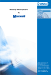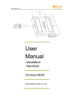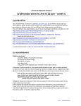
1
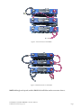
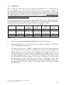
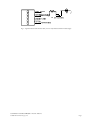
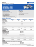
USER MANUAL Maxwell Technologies® BOOSTCAP® Energy Storage Modules User Manual for 16 V and 48 V Modules: 16 V Series: BMOD0500-E016 BMOD0500-P016 BMOD0500-P016 BMOD0250-E016 BMOD0250-P016 BMOD0110-E016 BMOD0110-P016 © 2007 Maxwell Technologies Inc. ® B01 B01 B02 B01 B01 B01 B01 48 V Series: BMOD0165-E048 BMOD0165-P048 BMOD0110-E048 BMOD0110-P048 BMOD0083-E048 BMOD0083-P048 B01 B01 B01 B01 B01 B01 1008491.8 1. Introduction The 16 V and 48 V series energy storage modules are self-contained energy storage devices comprised of either six or eighteen individual ultracapacitor cells respectively. The modules include bus bar connections, and integral active balance or voltage management circuitry. Units may be connected in series to obtain higher operating voltages, parallel to provide additional energy storage, or a combination of series/parallel arrangements for higher voltages and energy. There is a voltage management circuit that functions primarily to protect every cell from operating in a damaging over voltage condition. A passive (resistive) balancing version of the The 500F module is also available. The module packaging for those capacitances of 250F and above is a heavy-duty aluminum extruded enclosure. The enclosure is a permanently sealed, water-resistant device (per IEC 529 – IP65) requiring no maintenance. The package for the BMOD0110 consists of a plastic housing with a metallic cover for thermal transfer. The voltage management electronics has a single open collector logic output which indicates if any cell within the module is experiencing an over voltage condition. There is one temperature monitor output in the form of an NTC thermistor. 2. Unpacking Inspect the shipping carton for signs of damage prior to unpacking the module. Damage to the shipping carton or module should be reported to the carrier immediately. Remove the module from the shipping carton and retain the shipping materials until the unit has been inspected and is determined to be operational. NOTE: The original shipping materials are approved for both air and ground shipment). The module should be removed from the shipping carton by lifting it by the module body and not the terminal posts. The shipping container should contain the following: 1 x Energy storage module, part number determined by module type 1 x Accessory kit If the unit is found to be defective or any parts are missing, contact your supplier. A Return Material Authorization (RMA) number must be issued prior to returning the unit for repair or replacement. User Manual – 16 V and 48 V Modules – Doc. No. 1008491.8 © 2008 Maxwell Technologies, Inc. ® Page 1 3. Installation 3.1 Mechanical Modules are mountable and may be operated in any orientation. Two mounting surfaces are available on the modules over 200F, one at the top and the other at the bottom surface. These top and bottom plates are designed to support the module with no additional mechanical contact. See data sheet for available mounting locations. The BMOD110 only have the ability to be mounted from one side that is with the bottom down to the mounting surface. Each module is provided with an M5 threaded vent hole on the front panel. The module is shipped from the factory with a screw threaded into this threaded hole and the use of the hole as a vent is optional. The module is completely sealed, but if the application requires remote venting, an M5 threaded hose barb is provided in the accessory kit. Remove the screw which is in the hole when the module is received and replace it with the hose barb from that kit. Attach a 5/32 ID hose (4mm), preferable Teflon or Polypropylene, to the hose barb and route the hose to a safe venting location. In the event of cell venting the cell may release gas which will build pressure in the module. That pressure can be relieved through the vent tube. 3.2 Electrical WARNING CAUTION To avoid arcing and sparking the energy storage module should be in a discharged state and the system power disconnected during installation. The module is shipped discharged and with a shorting wire. Shorting wire should be removed prior to electrical connections. WARNING CAUTION To provide the lowest possible ESR the energy storage modules are not fused. Care should be taken within the application to prevent excessive current flow as required. Excessive current and/or duty cycle will result in overheating the module which will cause irreparable damage. Please consult the specific data sheet for each module for current and duty cycle capabilities. NOTE: The chassis of the module should be connected to system ground through any of the mounting holes with large enough gauge wire to carry the worst-case fault current. You will need to scrape off the anodize to ensure proper contact. User Manual – 16 V and 48 V Modules – Doc. No. 1008491.8 © 2008 Maxwell Technologies, Inc. ® Page 2 3.2.1 Output Terminal Posts The output terminals of the module consist of internally threaded aluminum posts. Maximum thread depth is 15 mm. They are designed to connect directly to a ring lug or a bus bar. Apply a layer of anti-oxidant joint compound (high conductivity aluminum-aluminum. For example, Noalox® Anti-Oxidant Compound available from IDEAL is a viable choice. There are many other vendors that supply equivalent compounds.) between the mating surfaces. The positive terminal is threaded for M8 x 1.25 steel bolts. The negative terminal is threaded for M10 x 1.5 steel bolts. Wave washers are required to ensure long term, reliable connections. When applying torque to the terminals it is recommended to use the maximum torque for the M8 and for the M10 bolts and for aluminum threads. Anti-rotation features within the module prevent damage of the terminals when apply torque to the bolts. Attachment to the output terminals should be made with ring lugs or bus bars of an appropriate size for the application current. The energy storage modules have a low ESR. As a result, the resistance of the wires connecting the energy storage module to the application can easily exceed the ESR of the module. Connection of modules in series or parallel should utilize the same gauge wire (or equivalent bus bar) as determined for final output connections. When connecting in series connect the positive output terminal of one module to the negative output terminal of the next module. Two possible orientations are illustrated in Figure 1. Figure 1: Possible series connection arrangements User Manual – 16 V and 48 V Modules – Doc. No. 1008491.8 © 2008 Maxwell Technologies, Inc. ® Page 3 Up to 15 modules may be connected in series for high voltage applications. Electric isolation of the module is tested to 2500 VDC. UL810a compliance is satisfied for up to 3x 165F, 48V modules in series or 9x 500F, 16V modules in series (maximum operating voltage of 150V) When several modules are connected in series for operating at higher voltage, care must be taken to ensure proper creepage and clearance distances in compliance with national safety standards for electrical equipment. When connecting modules in combination of series and parallel, the series strings should be interconnected first. The parallel connections will be made at the end points of the series string at the negative-to-negative and positive-to-positive terminal posts. 3.2.2 Module to module Connections The 16V and 48V modules are equipped with the active voltage management circuit that protects and monitors every cell within the module. Module-to-module balancing is not required. Figure 2 – Series Connection of 48V Modules User Manual – 16 V and 48 V Modules – Doc. No. 1008491.8 © 2008 Maxwell Technologies, Inc. ® Figure 3 – Parallel Connection of 48V Modules Page 4 Figure 4 – Series Connection of 16V Modules Figure 5 – Parallel Connection of 16V Modules NOTE: Although not depicted, modules BMOD0110 will follow similar connection schemes. User Manual – 16 V and 48 V Modules – Doc. No. 1008491.8 © 2008 Maxwell Technologies, Inc. ® Page 5 3.2.3 Logic outputs There is a single open collector logic output for voltage monitoring available for use as an optional feature. This output will indicate if any cell in the module has gone into an over voltage condition. In addition, the output of the NTC thermistor is also available for module temperature monitoring. The over voltage signal and temperature signal are available via the connector supplied with the module. Note: The passive version of the BMOD0500 only provides the output of the NTC thermistor for temperature monitor signal. There is no voltage monitoring signal in this module The logic outputs are isolated from the capacitor voltages and from chassis ground. The logic outputs may be operated individually or wire-or’d to provide a single fault line. A table indicating the pin out, indication and maximum current is provided below. The maximum open circuit voltage is 5.5 VDC. Pin # Wire Color 1 2 Black White 3 4 Red Green Pin out designation GRND VMC Active Not used TEMP Output (16 V) Output (48 V) High – Inactive High – Inactive Low - Active Low - Active N/A N/A Maximum current 5 mA N/A NOTE: 1. The Pin #2 is not used for the BMOD0500 P016 B02 featuring a passive balancing. 2. The high voltage will trip if any one cell goes into an over voltage condition (2.8V nominal with 2.73V – 2.86V range due to tolerances) 3. The output of Pin 2 (wrt Pin 1, GRND) is normally close to 0V when the voltage management circuit is inactive. However, in order to use the signal, the user needs to connect a pull-up resistor (typically 1kΩ) to Pin 2 and a 5V supply. In this configuration, the voltage at Pin 2 will be ~ 5V when the circuit is not active. When a cell in the module goes into over voltage condition (>2.7V), the voltage management circuit becomes active and tries to discharge the cell to bring its voltage below the threshold. At this time, the output of Pin 2 goes low. At this point, the circuit is setup to sink 5mA which can be used as a signal to the system electronics to stop charging in order to allow the cell(s) to discharge down to normal voltage levels (< 2.73V). Once this happens, the pin output goes high again and can be used as a signal to resume charging. Figure 6 shows a typical connection to use this system. User Manual – 16 V and 48 V Modules – Doc. No. 1008491.8 © 2008 Maxwell Technologies, Inc. ® Page 6 Fig. 6 – Typical connection to the monitor cable. (Users to verify values based on their circuit design) User Manual – 16 V and 48 V Modules – Doc. No. 1008491.8 © 2008 Maxwell Technologies, Inc. ® Page 7 The temperature output operates at any module voltage including zero volts. The TEMP output is via a NTC thermistor and can be measured between the pin 4 and pin 1 (GND) of the connector. The resistance of the thermistor varies with temperature to provide actual temperature output of the module. The thermistor is located within the module center. Under normal operating conditions the temperature output should represent the module hot spot. The resistance measured through the thermistor relates to temperature according to the US Sensor 10K @ 25ºC resistance to temperature chart for the 103JM1A. http://www.ussensor.com/rt%20charts/103JM1A.htm A mating connector for the output logic is provided with 6” (15 cm) of cable length. Additional 22 gauge wire may be spliced for longer wire length up to 6 feet (1.8 m). For lengths longer than 6 feet (1.8 m) shielded 4 conductor wire is recommended. 3.3 Thermal Performance Low internal resistance of the energy storage modules enables low heat generation within the modules during use. As with any electronic components the cooler the part operates the longer the service life. In most applications natural air convection should provide adequate cooling. In severe applications requiring maximum service life, forced airflow may be required. The thermal resistance, Rth, of the units has been experimentally determined assuming free convection at ambient (~ 25 oC). The Rth value provided on the data sheet is useful for determining the operating limits for the units. Using the Rth value a module temperature rise can be determined based upon any current and duty cycle. The temperature rise can be expressed by the following equation. ∆T = I 2 Resr Rth d f where: I = current AC or DC (amps) Resr = resistance Rac for AC current or Rdc for DC current (ohms) Rth = thermal resistance (oC/W) df = duty cycle fraction This ∆T plus ambient should remain below the specified maximum operating temperature for the module (please refer to the module datasheet) as measured by the thermistor output. If forced cooling methods are employed, it is possible to operate the units at higher currents or duty cycles than if only passive cooling is utilized. User Manual – 16 V and 48 V Modules – Doc. No. 1008491.8 © 2008 Maxwell Technologies, Inc. ® Page 8 4. Accessories The following accessories are provided with modules within the accessory kit. 5. 1 x Users manual 1 x 4 wire monitor cable. Used for voltage output and temperature monitoring 1 x Hex head cap, M10x16, Zinc plated screw 1 x Hex head cap, M8x16, Zinc plated screw 1 x SRTG6 – Misumi, Barbed coupler. Optional item providing venting capability. Operation Module should only be operated within specified voltage and temperature ratings. Determine whether current limiting is necessary on input/output based on current ratings of ancillary devices. Observe polarity indicated on module. Reverse polarity operation of the module(s) is not recommended. 6. Safety Do not operate unit above specified voltage. Do not operate unit above specified temperature rating. Do not touch terminals with conductors while charged. Serious burns, shock, or material fusing may occur. Protect surrounding electrical components from incidental contact. Provide sufficient electrical isolation when working above 50 V DC. 7. Maintenance Periodically check the main power terminal connections. Retighten the terminal bolts as necessary. Prior to any handling, ensure energy storage unit is completely discharged. The stored energy and the voltage levels may be lethal if mishandling occurs. User Manual – 16 V and 48 V Modules – Doc. No. 1008491.8 © 2008 Maxwell Technologies, Inc. ® Page 9 8. Storage The module can be stored in the original package discharged in a dry place. Discharge used module prior to stock or shipment. A wire across the terminals may be used to maintain short circuit after having discharged the module. 9. Disposal Do not dispose of module in trash. Dispose of according to local regulations. 10. Specifications Refer to datasheets on our website, www.maxwell.com, for specifications for each specific product. User Manual – 16 V and 48 V Modules – Doc. No. 1008491.8 © 2008 Maxwell Technologies, Inc. ® Page 10 Contact Information: US Office & Worldwide Headquarters Maxwell Technologies Inc. 9244 Balboa Avenue San Diego, CA 92123, USA Phone: +1-858-503-3300 USA Free call: 1-877-511-4324 Fax: +1-858-503-3301 European Office Maxwell Technologies SA CH1728 Rossens, Switzerland Phone: +41-(0)26-411-85-00 Fax: +41-(0)26-411-85-05 Asia Pacific Office Maxwell Technologies Asia Rm.2104, Suncome Liauw's Plaza 738 Shang Cheng Road, Pudong New Area Shanghai 200120, P.R. China Tel: +86-21-5836-5733 Fax: +86-21-5836-5620 Refer to our website www.maxwell.com for full terms and conditions. Disclaimer of Warranty/Limitation of Liability for Uses in Life Support Devices or Critical Systems Maxwell Technologies, Inc. and its Affiliates (“Maxwell”) provide no warranties of any kind either express or implied, including (without limitation) the implied warranties of merchantability and fitness, for uses of its products as components in life support devices or critical systems. “Life support devices” are devices or systems, which (a) are intended for surgical implant into a living body, or (b) support or sustain life, and whose failure to perform when properly used in accordance with the instructions provided in the labeling can be reasonably expected to result in bodily injury to the user. An example of a life support device includes, but is not limited to, a heart pacemaker. A “critical system” is any system whose failure to perform can affect the safety or effectiveness of a higher level system, or cause bodily or property injury by loss of control of the higher level device or system. An example of a critical system includes, but is not limited to, aircraft avionics. You agree that Maxwell will not be liable to you for any loss or damages, whether actual or consequential, indirect, punitive, special, or incidental, arising out of or relating to these terms. These terms are a non-waivable condition to any contract that Maxwell may enter into. An exception to these terms may only be authorized in a writing signed by the President of Maxwell or a duly authorized officer. © 2007 Maxwell Technologies Inc. ®