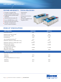
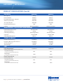
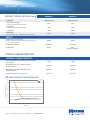
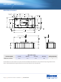
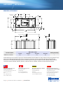
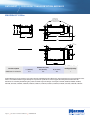
1
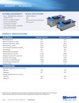
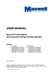
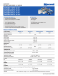
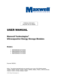
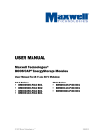
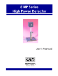
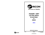
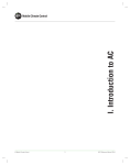
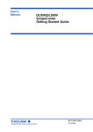
ULTRACAPACITORS BUS APPLICATION BRIEF REVOLUTIONIZING HOW THE WORLD MOVES PEOPLE. Carbon emissions, the depletion of natural resources, traffic congestion and the rising costs of fossil fuels are all issues pushing the world to search for alternative means of transportation. Mass-transit buses, fleet vehicles, trains and heavy-transportation vehicles all benefit from the adoption of a hybrid power train approach with the use of ultracapacitors. Ultracapacitors quickly capture energy from braking and then use that energy to provide a short burst of power during acceleration to dramatically reduce the use of fuel in a conventional internal combustion engine or battery drain in an electric/hybrid system. Maxwell ultracapacitors are compact, high-performance, have exceptionally long-life and fulfill many of the functions of batteries but with dramatically higher reliability and are virtually impervious to any climate condition. Ultracapacitors: Green technology: Ideal for: Used in over 4,000 buses worldwide: Breakthrough energy storage and delivery devices Regenerative braking systems Start-stop systems Cold climate starting Hybrid electric vehicles: • Buses, trains, trolleys, light rail High efficiency with fewer CO2 emissions Lead free MAN Gillig New Flyer NYC Hybrid BAE Bus ULTRACAPACITORS BUS APPLICATION BRIEF Specifications K2 Series 48 V Modules 125 V Modules 650 - 3,000 F 83 - 165 F 63 F Voltage 2.70 V 48 V 125 V ESR, DC 0.29 - 0.8 mohm 6.3 - 10 mohm 18 mohm 1.5 - 5.2 mA 3.0 - 5.2 mA 10 mA Emax 4.1 - 6.0 Wh/kg 2.6 - 3.9 Wh/kg 2.3 Wh/kg Pmax 12,000 - 14,000 W/kg 5,600 - 6,800 W/kg 3,600 W/kg Capacitance Leakage Current Images not to scale. Maxwell Technologies, Inc. Global Headquarters 5271 Viewridge Court, Suite 100 San Diego, CA 92123 USA Tel: +1 858 503 3300 Fax: +1 858 503 3301 maxwell.com Maxwell Technologies SA CH-1728 Rossens Switzerland Tel: +41 (0)26 411 85 00 Fax: +41 (0)26 411 85 05 Maxwell Technologies, GmbH Brucker Strasse 21 D-82205 Gilching Germany Tel: +49 (0)8105 24 16 10 Fax: +49 (0)8105 24 16 19 Maxwell Technologies, Inc. Shanghai Representative Office 13E, CR Times Square 500 Zhangyang Road, Pudong Shanghai 200122, P.R. China Tel: +86 21 5836 8780 Fax: +86 21 5836 8790 ULTRACAPACITORS GRID STORAGE APPLICATION BRIEF Standard 20’ container holds 1MW/60 seconds of energy storage 1MW • 60 SECONDS • 1,000,000 CHARGE-DISCHARGE CYCLES ENERGY STORAGE As renewable energy sources grow in use and the percentage of grid power met by renewables increases grid stability becomes an increasingly important issue. The variability in wind and solar output creates instability on the grid. This variability also results in poor utilization of these resources by 30-50%. Maxwell ultracapacitors can help combat these challenges by providing a few seconds of reactive power in a cost effective and smaller package size. The long life, high power and superior charge/discharge cycling of ultracapacitors make them the ideal energy storage for firming the output of renewable installations. With Maxwell ultrapacitors energy storage, it is easy to design scalable systems with lifetimes over a million charge/discharge cycles at 100% depth of discharge. Renewables ride-through and firming, Hybrid Energy Storage Systems component Applications VARs support Regulation up, regulation down Renewable energy firming – wind or solar smoothing Frequency regulation Maxwell Technologies Over 11 GW total power installed Scaleable energy storage 560V/1MW/60 seconds 20 foot container Add your power electronics and controls Green Technology Lead free No toxic materials ULTRACAPACITORS GRID STORAGE APPLICATION BRIEF Specifications 48 V Module 56 V Module 165 F 130 F Voltage 48 V 56 V ESR, DC 6.3 mohm 8.1 mohm 5.2 mA 120 mA Emax 3.9 Wh/kg 3.1 Wh/kg Pmax 6,800 W/kg 5,400 W/kg Capacitance Leakage Current 1 MW / 60 Sec. / 1 Million Cycle Module Specifications 646 x 48 V Modules 500 x 56 V Modules Capacitance 372 F 650 F Voltage 740 V 560 V Floor Space* 106 ft2 89 ft2 Peak Power** 23 MW 23 MW Average Power** 1 MW 1 MW Configuration * 6’ height ** 75% Depth of discharge Images not to scale Maxwell Technologies, Inc. Global Headquarters 5271 Viewridge Court, Suite 100 San Diego, CA 92123 USA Tel: +1 858 503 3300 Fax: +1 858 503 3301 maxwell.com Maxwell Technologies SA CH-1728 Rossens Switzerland Tel: +41 (0)26 411 85 00 Fax: +41 (0)26 411 85 05 Maxwell Technologies, GmbH Brucker Strasse 21 D-82205 Gilching Germany Tel: +49 (0)8105 24 16 10 Fax: +49 (0)8105 24 16 19 Maxwell Technologies, Inc. Shanghai Representative Office 13E, CR Times Square 500 Zhangyang Road, Pudong Shanghai 200122, P.R. China Tel: +86 21 5836 8780 Fax: +86 21 5836 8790 DATASHEET 48V MODULES FEATURES AND BENEFITS TYPICAL APPLICATIONS Compact, rugged, fully enclosed splash proof design Highest power performance available Individually balanced cells Over 1,000,000 duty cycles Ultra-low internal resistance Voltage & temperature sensor output included Automotive Industrial Telecommunications Bus, Train Uninterruptible Power Supplies (UPS) PRODUCT SPECIFICATIONS ELECTRICAL Rated Capacitance 1 Minimum Capacitance, initial Maximum ESR DC, initial 1 1 Rated Voltage Absolute Maximum Voltage 14 Maximum Continuous Current (ΔT = 15 C) BMOD0083 BMOD0165 83 F 165 F 83 F 165 F 10 mΩ 6.3 mΩ 48 V 48 V 51 V 51 V 61 ARMS 77 ARMS Maximum Continuous Current (ΔT = 40oC)2 100 ARMS 130 ARMS Maximum Peak Current, 1 second (non repetitive)3 1,100 A 1,900 A Leakage Current, maximum (B01 Suffix - VMS 2.0)4 3.0 mA 5.2 mA 750 V 750 V Minimum -40oC -40oC Maximum 65 C 65oC Minimum -40oC -40oC Maximum 70oC 70oC o 2 Maximum Series Voltage TEMPERATURE Operating Temperature (Ambient temperature) o Storage Temperature (Stored uncharged) Page 1 Document number: 1009365.11 maxwell.com DATASHEET 48V MODULES PRODUCT SPECIFICATIONS (Cont’d) PHYSICAL BMOD0083 BMOD0165 Mass, typical 10.3 kg 13.5 kg Power Terminals M8/M10 M8/M10 Recommended Torque - Terminal 20/30 Nm 20/30 Nm Vibration Specification SAE J2380 SAE J2380 Shock Specification SAE J2464 SAE J2464 IP65 IP65 Natural Convection Natural Convection Environmental Protection Cooling MONITORING / CELL VOLTAGE MANAGEMENT Internal Temperature Sensor NTC Thermistor NTC Thermistor Temperature Interface Analog Analog Cell Voltage Monitoring Overvoltage Alarm Overvoltage Alarm Deutsch DTM Deutsch DTM VMS 2.0 VMS 2.0 2,700 W/kg 3,300 W/kg 5,600 W/kg 6,800 W/kg 2.6 Wh/kg 3.9 Wh/kg 26.6 Wh 52.8 Wh High Temperature1 1,500 hours 1,500 hours Capacitance Change 20% 20% ESR Change 100% 100% Room Temperature1 10 years 10 years Capacitance Change 20% 20% ESR Change 100% 100% Connector Cell Voltage Management POWER & ENERGY Usable Specific Power, Pd5 Impedance Match Specific Power, Pmax 6 Specific Energy, Emax7 Stored Energy 8 LIFE (at Rated Voltage & Maximum Operating Temperature) (% decrease from minimum initial value) (% increase from maximum initial value) (at Rated Voltage & 25oC) (% decrease from minimum initial value) (% increase from maximum initial value) Page 2 Document number: 1009365.11 maxwell.com DATASHEET 48V MODULES PRODUCT SPECIFICATIONS (Cont’d) BMOD0083 BMOD0165 1,000,000 cycles 1,000,000 cycles Capacitance Change 20% 20% ESR Change 100% 100% Test Current 100 A 100 A 2 years 2 years 4,800 A 7,600 A 2,500 V DC 2,500 V DC RoHS RoHS UL810a (150 Volts) 1oC/W 1oC/W Thermal Resistance (Rma, Module Case to Ambient), typical 0.30oC/W 0.25oC/W Thermal Resistance (Rca, All Cell Cases to Ambient), typical 0.40oC/W 0.40oC/W Thermal Capacitance (Cth), typical 2 7,675 J/oC 12,715 J/oC Cycle Life1,9 (% decrease from minimum initial value) (% increase from maximum initial value) Shelf Life 1,10 (Stored uncharged up to a maximum storage temperature) SAFETY Short Circuit Current, typical (Current possible with short circuit from rated voltage. Do not use as an operating current.) Factory High-Pot Test13 Certifications TYPICAL CHARACTERISTICS THERMAL CHARACTERISTICS Thermal Resistance (Rcm, One Cell Case to Module Case), typical2 ESR AND CAPACITANCE VS TEMPERATURE 180% Capacitance DC ESR Percentage change from value at 25°C 170% 160% 150% 140% 130% 120% 110% 100% 90% 80% -60 -40 -20 0 20 40 60 Temperature (°C) Page 3 Document number: 1009365.11 maxwell.com 80 DATASHEET 48V MODULES NOTES 1. Capacitance and ESRDC measured at 25°C per Document Number 1007239 available at www.maxwell.com. 2. Per Maxwell Document 1007239 available at www.maxwell.com. ½ CV 3. Maximum Peak current (1 sec) = C x ESRDC + 1 4. After 72 hours at 25°C and rated voltage. Initial leakage current can be higher. 0.12V2 5. Per IEC 62391-2, Pd = ESR x mass DC V2 6. Pmax = 4 x ESRDC x mass 7. Emax = ½ CV2 3,600 x mass MOUNTING RECOMMENDATIONS Please refer to the user manual for installation recommendations. Page 4 Document number: 1009365.11 maxwell.com 8. Estored = ½ CV2 3,600 9. Cycle per Document Number 1007239 available at www.maxwell.com. 10. No more than 10% decrease in capacitance from minimum initial capacitance or 50% increase in ESR from maximum initial ESR. 11. Tested at 1 kV DC. 12. For a given application, sufficient cooling must be provided to keep cell case temperatures below 65°. See Rth. 13. Duration = 60 seconds. Not intended as an operating parameter. 14. Absolute maximum voltage non repeated, not to exceed 1 second. MARKINGS Products are marked with the following information: Rated capacitance, rated voltage, product number, name of manufacturer, positive and negative terminal, warning marking, serial number. DATASHEET 48V MODULES BMOD0083 P048 B01 4 M10 NEGATIVE TERMINAL 3 121 2 191 W MAX 156.5 1 1 174.2 1 54.3 1 D 2 8.7 0.25 THRU 8X 307.5 1 2X 116.4 2 121.2 1 170 0.25 C 2X 36.8 2 M8 POSITIVE TERMINAL VENT 10 0.5 34 2 10 0.5 33.5 1 396.2 0.25 418LMAX MONITOR CABLE 50 5 229 5 B 360 25 179H1 MAX 104H2 MAX A SIZE CAGE CODE B 68911 SCALE 4 3 1:5 DOC. NO. PART NO. 2 BMOD0083 P048 B01 L (max) 418 Dimensions (mm) W (max) H1 (max) 191 126 H2 (max) Package Quantity 106 1 Product dimensions are for reference only unless otherwise identified. Product dimensions and specifications may change without notice. Please contact Maxwell Technologies directly for any technical specifications critical to application. Page 5 Document number: 1009365.11 maxwell.com REV 2 1 B-PG1 REV A 7/01 Part Description 107175 1015531 SHEET DATASHEET 48V MODULES BMOD0165 P048 B01 4 M10 NEGATIVE TERMINAL 3 121 2 191 W MAX 156.5 1 1 174.2 1 54.3 1 D 2 8X 307.5 1 2X 116.4 2 8.7 0.25 THRU 121.2 1 170 0.25 C 2X 36.8 2 M8 POSITIVE TERMINAL VENT 10 0.5 396.2 0.25 34 2 10 0.5 33.5 1 418LMAX MONITOR CABLE 229 5 50 5 360 25 B 179H1 MAX 157H2 MAX A SIZE CAGE CODE B 68911 4 B-PG1 REV A 7/01 Part Description BMOD0165 P048 B01 L (max) 418 Dimensions (mm) 3 W (max) H1 (max) 194 179 SCALE 2 1:5 PART NO. 108657B DOC. NO. REV 1015380 1 1 H2 (max) Package Quantity 157 1 Product dimensions are for reference only unless otherwise identified. Product dimensions and specifications may change without notice. Please contact Maxwell Technologies directly for any technical specifications critical to application. All products featured on this datasheet are covered by the following U.S. patents and their respective foreign counterparts: 7511942, 7307830, 7203056, 7027290, 7.352.558, 7.295.423, 7.090.946, 7.508.651, 7.492.571, 7.342.770, 6.643.119, 7.384.433, 7.147.674, 7.317.609, 7.495.349, 7.102.877. Maxwell Technologies, Inc. Global Headquarters 5271 Viewridge Court, Suite 100 San Diego, CA 92123 USA Tel: +1 858 503 3300 Fax: +1 858 503 3301 Page 6 Maxwell Technologies SA CH-1728 Rossens Switzerland Tel: +41 (0)26 411 85 00 Fax: +41 (0)26 411 85 05 Document number: 1009365.11 maxwell.com Maxwell Technologies, GmbH Brucker Strasse 21 D-82205 Gilching Germany Tel: +49 (0)8105 24 16 16 Fax: +49 (0)8105 24 16 19 Maxwell Technologies, Inc. Shanghai Representative Office 13E, CR Times Square 500 Zhangyang Road, Pudong Shanghai 200122, P.R. China Tel: +86 21 5836 8780 Fax: +86 21 5836 8790 SHEET 2 OF 2 DATASHEET 125V HEAVY TRANSPORTATION MODULES FEATURES AND BENEFITS TYPICAL APPLICATIONS CAN bus digital monitoring and communications Highest power performance available Over 1,000,000 duty cycles Temperature and voltage monitoring Ultra-low resistance Buses Electric trains and trolleys Heavy duty transportation Cranes, RTGS Utility vehicles Mining equipment PRODUCT SPECIFICATIONS ELECTRICAL Rated Capacitance BMOD0063 P125 B04/B08 63 F 1 Minimum Capacitance, initial Maximum ESR DC, initial 63 F 1 18 mΩ 1 Rated Voltage Absolute Maximum Voltage 125 V 136 V 15 Maximum Continuous Current (ΔT = 15 C) o 140 ARMS 2 Maximum Continuous Current (ΔT = 40oC)2 240 ARMS Maximum Peak Current, 1 second (non repetitive) 1,800 A Leakage Current, maximum (VMS 2.0) 10 mA Maximum Series Voltage 1,500 V 3 4 TEMPERATURE Operating Temperature (Ambient temperature) Minimum -40oC Maximum 65oC Storage Temperature (Stored uncharged) Minimum -40oC Maximum 70oC Page 1 Document number: 1014696.5 maxwell.com DATASHEET 125V HEAVY TRANSPORTATION MODULES PRODUCT SPECIFICATIONS (Cont’d) PHYSICAL Mass, typical BMOD0063 P125 B04/B08 60.5 kg 13 Power Terminals Radsok Recommended Torque - Terminal N/A Vibration Specification ISO16750-3 Table 14 Shock Specification SAE J2464 Environmental Protection IP65 Cooling Forced Air MONITORING / CELL VOLTAGE MANAGEMENT Temperature Interface Serial Data (CAN) Cell Voltage Monitoring Group Voltage (CAN) Connector Deutsch DTM Cell Voltage Management VMS 2.0 POWER & ENERGY Usable Specific Power, Pd5 1,700 W/kg Impedance Match Specific Power, Pmax Specific Energy, Emax 6 3,600 W/kg 2.3 Wh/kg 7 Stored Energy8 136.7 Wh LIFE High Temperature1 1,500 hours Capacitance Change 20% ESR Change 100% (at Rated Voltage & Maximum Operating Temperature) (% decrease from minimum initial value) (% increase from maximum initial value) Room Temperature1 10 years Capacitance Change 20% ESR Change 100% Cycle Life1,9 1,000,000 cycles (at Rated Voltage & 25oC) (% decrease from minimum initial value) (% increase from maximum initial value) Capacitance Change 20% ESR Change 100% Test Current 100 A (% decrease from minimum initial value) (% increase from maximum initial value) Shelf Life1,10 (Stored uncharged up to a maximum storage temperature) Page 2 Document number: 1014696.5 maxwell.com 2 years DATASHEET 125V HEAVY TRANSPORTATION MODULES PRODUCT SPECIFICATIONS (Cont’d) BMOD0063 P125 B04/B08 SAFETY Short Circuit Current, typical 6,900 A (Current possible with short circuit from rated voltage. Do not use as an operating current.) Factory High-Pot Test14 4,000 V DC RoHS eMark 72/245/EEC (B08 only) UN10.03 (B08 only) Certifications TYPICAL CHARACTERISTICS THERMAL CHARACTERISTICS Thermal Resistance (Rma, Modulel Case to Ambient), typical 0.01oC/W Thermal Resistance (Rca, All Cell Cases to Ambient), typical 0.04oC/W Thermal Capacitance (Cth), typical 2 33,370 J/oC ESR AND CAPACITANCE VS TEMPERATURE 180% Capacitance DC ESR Percentage change from value at 25°C 170% 160% 150% 140% 130% 120% 110% 100% 90% 80% -60 -40 -20 0 20 40 Temperature (°C) Page 3 Document number: 1014696.5 maxwell.com 60 80 DATASHEET 125V HEAVY TRANSPORTATION MODULES NOTES 1. Capacitance and ESRDC measured at 25°C per Document Number 1007239 available at www.maxwell.com. 2. Per Maxwell Document 1007239 available at www.maxwell.com. ½ CV 3. Maximum Peak current (1 sec) = C x ESRDC + 1 4. After 72 hours at 25°C and rated voltage. Initial leakage current can be higher. 0.12V2 5. Per IEC 62391-2, Pd = ESR x mass DC V2 6. Pmax = 4 x ESRDC x mass 7. Emax = ½ CV2 3,600 x mass MOUNTING RECOMMENDATIONS Please refer to the user manual for installation recommendations. Page 4 Document number: 1014696.5 maxwell.com 8. Estored = ½ CV2 3,600 9. Cycle per Document Number 1007239 available at www.maxwell.com. 10. No more than 10% decrease in capacitance from minimum initial capacitance or 50% increase in ESR from maximum initial ESR. 11. Tested at 1 kV DC. 12. For a given application, sufficient cooling must be provided to keep cell case temperatures below 65°. See Rth. 13. Without fan. With fan, mass is 63.4 kg. 14. Duration = 60 seconds. Not intended as an operating parameter. 15. Absolute maximum voltage non repeated, not to exceed 1 second. MARKINGS Products are marked with the following information: Rated capacitance, rated voltage, product number, name of manufacturer, positive and negative terminal, warning marking, serial number. DATASHEET 125V HEAVY TRANSPORTATION MODULES BMOD0063 P125 Bxx Part Description L (±0.5mm) Dimensions (mm) W (±0.2mm) H (±0.7mm) Package Quantity BMOD0063 P125 B04/08 619 425 265 1 Product dimensions are for reference only unless otherwise identified. Product dimensions and specifications may change without notice. Please contact Maxwell Technologies directly for any technical specifications critical to application. All products featured on this datasheet are covered by the following U.S. patents and their respective foreign counterparts: 7511942, 7307830, 7203056, 7180726, 7027290, 7.352.558, 7.295.423, 7.090.946, 7.508.651, 7.492.571, 7.342.770, 6.643.119, 7.384.433, 7.147.674, 7.317.609, 7.495.349, 7.102.877. Page 5 Document number: 1014696.5 maxwell.com DATASHEET 125V HEAVY TRANSPORTATION MODULES ORDERING INFORMATION Base Module 109120B BMOD0063 P125 B0463F/125V Module with CAN Comm. 109024B BMOD0063 P125 B0863F/125V e-mark Module with CAN Comm. Power Connection Kit 109131 Power Connection Kit, 90DEG 109132 Power Connection Kit, STRAIGHT Communication Kit 109133 CAN SIGNAL, Deutsch Fan Kit 109134 129036 FAN KIT, 24V Standard FAN KIT, 24V, E-Mark Maxwell Technologies, Inc. Global Headquarters 5271 Viewridge Court, Suite 100 San Diego, CA 92123 USA Tel: +1 858 503 3300 Fax: +1 858 503 3301 Page 6 Maxwell Technologies SA CH-1728 Rossens Switzerland Tel: +41 (0)26 411 85 00 Fax: +41 (0)26 411 85 05 Document number: 1014696.5 maxwell.com Maxwell Technologies, GmbH Brucker Strasse 21 D-82205 Gilching Germany Tel: +49 (0)8105 24 16 16 Fax: +49 (0)8105 24 16 19 Maxwell Technologies, Inc. Shanghai Representative Office 13E, CR Times Square 500 Zhangyang Road, Pudong Shanghai 200122, P.R. China Tel: +86 21 5836 8780 Fax: +86 21 5836 8790