1
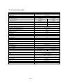
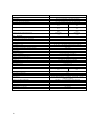
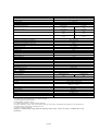
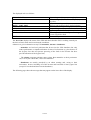
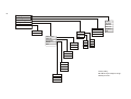
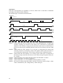
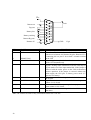
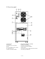
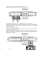
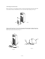
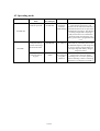
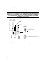
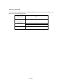
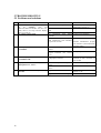
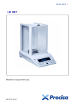
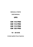
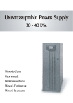
ETM6k5-10kVA
PowerElite MultiTec UPS
Installation and Operation
Manual
MAN451
OPERATING MANUAL
We thank you for having chosen our product
The manufacturer specializes in the development and production of Uninterruptible Power Supply (UPS). These
UPS system are high quality products, carefully designed to meet the highest performance standards.
These UPS systems have been designed according to ON LINE - DOUBLE CONVERSION SINE VAWE
technology.
This user’s manual contains detailed instructions on UPS operation and care. In order to get the best performance
from your UPS, please read and follow carefully the instructions described in the following pages. It is
recommended that you keep this manual beside your equipment.
© No part of this manual may be reproduced in any way without the approval of the manufacturer. Data and
drawings are subject to changes without notice and without obligation on the manufacturer’s.
WARNING: This unit is a class A (EN50091-2 UPS - EMC requirement specifications). In a
domestic environment it may produce radio interference, users may have to adopt further
precautions.
2
MAN451
USER’S MANUAL
1 PRECAUTIONS AND SAFETY REGULATIONS
2 DESCRIPTION OF UPS
2.1 General characteristics of UPS.
2.2 Description of UPS
2.3 Technical data table
2.4 Control/warning light panel
2.4.1
2.4.2
2.4.3
2.4.4
Indicator/warning LEDs
Control/consultation keys
LCD display
Buzzer
2.5 Interface
2.5.1
2.5.2
2.5.3
2.5.4
RS232
Remote controls
E.P.O.
Expansion slots
3 INSTALLATION
3.1 Installation area requirements
3.2 Preliminary tasks
3.3 View of rear panel
3.4 Connections
3.4.1
3.4.2
3.4.3
3.4.4
Connection of single phase mains and load
Connection of tree-phase mains and single-phase load
Battery expansion connection
Fixing the wheel-lock peg
4 SWITCHING ON THE UPS AND OPERATING MODES
4.1 Procedure for switching on and off
4.1.1
4.1.2
4.1.3
Switching on the UPS with mains power
Switching on the UPS with battery power
Switching off the UPS
4.2 Operating modes
4.2.1
SMART-ACTIVE
4.3 Maintenance by-pass
4.3.1
4.3.2
Maintenance by-pass remote connection
Fuse replacement
5 TROUBLESHOOTING
5.1 Problems and solutions
MAN451
1 PRECAUTIONS AND SAFETY REGULATIONS
This part of the manual contains precautions that must be strictly observed as they concern
SAFETY.
a) The UPS MUST NOT BE USED WITHOUT A PROPER EARTH CONNECTION. The
first connection to be made must be the earth (ground), to be connected to the terminal
marked PE.
b) The UPS MUST NOT BE USED WITHOUT A PROPER NEUTRAL CONNECTION.
Failure to provide a proper neutral connection could damage the UPS.
c) Caution: do not connect the output neutral to the input neutral or earth as doing so could
damage the UPS.
d) The interior of the UPS is live and DANGEROUS. All installation and maintenance
tasks must be carried out by properly qualified personnel ONLY.
e) The UPS contains an energy source (i.e. the batteries): The output terminals may
therefore be live even when the UPS is not connected to the mains.
f) Full battery voltage may cause electric shock. Old batteries are to be treated as TOXIC
WASTE and handled accordingly. Never throw batteries into a fire: they could explode.
Do not attempt to open the batteries: they are maintenance-free. Bear in mind also that
the electrolyte is dangerous for skin and eyes and may be toxic.
g) If you notice any liquid seepage or any residual white dust DO NOT switch on the UPS.
h) Make sure that water, liquids in general and/or any other foreign objects do not enter the
UPS.
i)
In the event of danger switch off the UPS via the switch at the rear and turn all switches
to off.
j)
If necessary, replace all blown fuses with others of exactly the same type.
k) The UPS generates a leakage current of less than 10mA.
Warning: the load leakage current should be summed with that of the UPS on the earth
protection conductor.
l)
For battery expansion use only supplied connectors or those authorised by the company.
m) The UPS units in this series have been designed for professional use and are unsuitable
for domestic use.
4
2 DESCRIPTION OF THE UPS
2.1 General characteristics of the UPS.
The UPS units in this series feature the following:
•
•
•
•
•
•
•
•
•
•
•
•
•
•
•
•
•
•
•
•
•
•
•
•
Double conversion on-line system
By-pass: automatic by-pass utilising bi-directional static switch.
Maintenance by-pass without interruption of load feed.
Control of input power factor for a sinusoidal absorbed current and in phase with mains
voltage (0.99 single-phase input, 0.95 tri-phase input).
Hold-up time ≥ 40ms which together with a wide permissible variation for mains voltage
(V AC min=170 V AC @ 100% load and V AC min=140 V AC @ 50% load) allows a
reduction in the number of times battery power is used.
LRCD (Low Ripple Current Discharge) system which gives a low-ripple battery
discharge current at 50/100Hz even with highly distorting loads.
Microcontroller (16 bit) with on-board flash memory for total control of the UPS.
Remote monitoring of UPS via an RS232 interface, a contact port and an expansion slot
that allows insertion of the type of interface most suited to your needs (USB, SNMP,
modem etc.).
Multistandard operating mode that includes three machine operating modes:
ON-LINE
LINE INTERACTIVE (Stand-by on)
SMART ACTIVE
Silent, economic running thanks to fan speed control and high efficiency (ON-LINE
mode: 91% on battery or single-phase mains, 92% with tree-phase mains; LINE
INTERACTIVE or
SMART-ACTIVE modes: 98%).
Auxiliary redundant power feed that allows operation of by-pass even in the event of
main auxiliary power feed failure.
Front-rear ventilation to reduce effective overall dimensions by eliminating the need for
side clearances.
Use of IGBT as switching devices.
Self-select of output frequencies.
Battery test, automatic or manual.
Unlimited expandability via external battery box.
LCD display, 2x20, backlight, for easy setting and monitoring of UPS, mains and charge
status.
Weekly programming function for setting on/off sequences
Stand-by function
Conformity with standards in force concerning safety and electromagnetic compatibility.
MAN451
2.2 Description of the UPS
The purpose of a UPS is to guarantee perfect power supply voltage to the connected equipment.
Once connected and powered, the UPS generates an alternating sinusoidal voltage of stable
amplitude and frequency, independent of any mains surges and/or fluctuations.
As long as the UPS draws power from the mains, the batteries are kept charged under the
control of a microprocessor. This microprocessor continually monitors mains voltage amplitude
and frequency, the amplitude and frequency generated by the inverter, the applied charge,
internal temperature and battery efficiency.
There follows a block diagram of the UPS (see Fig.1) and a description of its individual parts.
Input and output EMI filters
Input and output filters for electromagnetic disturbances on the supply.
Power Board
This manages the power.
Rectifier/Boost: these represent the input stage. With mains power on it converts the input AC
voltage into two DC voltages (first conversion), one +400 V and the other –400V with respect
to the neutral, which power the inverter and the battery charger. Opening and closing of the
boost IGBT’s is modulated in such a way as to guarantee sinusoidal current absorption at the
input. When working in the absence of mains power it behaves like a DC-DC converter that
raises the voltages of the two battery sets to +400V and –400V. The boosts uses a “Step-up”
configuration without insulation.
Inverter: the inverter transforms continuous boost-supplied voltages into a stabilised sinusoidal
alternating voltage (second conversion) used for charging. A half-bridge configuration without
insulation with IGBT’s operating at 18KHz is employed.
Automatic Static by-pass
The automatic by-pass is an scr (static) device which automatically connects the UPS output on
the input mains in the event of overload and/or an inverter fault. It is equipped with an auxiliary
redundant power supply so that it can be powered in the event of a mains failure.
Stand-by Switch
Electromechanical device that automatically disconnects UPS inverter output from the charge
in the following cases:
in stand-by, in by-pass status during on-line mode, in the event of an inverter fault or if the
Emergency Power Off (E.P.O.) button is pressed.
Battery Charger
Made up of two DC-DC converters that draw, under the control of the microprocessor, the
continuous +400V and –400V voltages, lowering them to a voltage level suitable for the battery
sets to be charged. Batter recharge uses a current of approximately 1 Ampere and lasts from 6
to 8 hours depending on the initial battery charge. The battery charger is deactivated when
mains power is cut.
6
Maintenance by-pass
By closing the maintenance by-pass (SWMB) switch and then opening the SWIN and SWOUT
switches it is possible to carry out maintenance work on the UPS in total safety without having
to interrupt the power to the load. The auxiliary contact that informs the microcontroller of
switch closure is made available on the input terminal block so as to allow installation of an
additional external maintenance by-pass.
Control and µC Board
These are the boards that control and supervise the UPS
Interface Board
Contains an RS232 interface as standard, a contact port and the isolated emergency power off
(E.P.O.)
Interface Slot
This is an expansion slot that allows the user to insert an extra interface: a second serial RS232
or a SNMP interface etc.
MAN451
8
SWMB
Maintenance By-pass
Switch
Interface slot
CONTROL BOARD
E.P.O .
uC Board
Interface
Board
Remote
controls
Display
Board
SWBYP by-pass fuse
RS232
POWER BOARD
RECTIFIER
BOOST
Line In
SWIN
Input
breakr
IEC 10A max
Stand-by
Switch
Output
EMI
Filter
Line Out
SWOUT
Output
breaker
BATTERY
CHARGER
SWBT
+
IEC Fuse
INVERTER
Input
EMI
Filter
SWBT
To
battery
extension
Automatic
Static By-pass
-
+ Battery
- Battery
SWBT
N
SWBT
N
UPS BLOCK DIAGRAM
Neutral
2.3 Technical data tables
MODEL
INPUT
Rated voltage
Accepted range
Min voltage for non-trip of battery
Rated frequency
Maximum input current (1)
10000 VA
230 V AC single-phase or tri-phase with neutral
0 – 276 V AC
170 V AC @ 100% load / 140 V AC @ 50% load
50 – 60 Hz + 5 Hz
Single phase
Tri-phase
50 A
18 A
Single phase
Tri-phase
37 A
13 A
Single phase
Tri-phase
≥0.99
≥0.95
Single phase
Single phase
< 6%
< 27%
Rated input current (2)
Power factor
Distortion current @ distorting load (3)
1.1
BY PASS
Voltage range accepted for commutation
Frequency range accepted for commutation
Inverter/by-pass commutation time 0.1ms
1.2
BATTERY
Autonomy in min / W
N° batteries / V / Ah
Recharge time
Rated voltage on autonomy expansion connector
1.3
OUTPUT
Rated voltage
Static variation (4)
Dynamic variation (5)
Wave form
Voltage distortion @ linear load (3)
Distortion voltage @ distorting load (3)
Frequency (6)
Current peak factor
Rated power in VA / W
Short circuit current
1.4
VARIOUS
1.5
Leakage current to ground
AC/AC efficiency
180 – 264 V AC
Selected frequency ±5 Hz
0.1 ms
8’ / 7000 W
15+15 / 12V / 7 Ah (High Current Discharge Capability)
6-8 h
±180 V DC
220 / 230 / 240 V AC selectable + 2%
< 1%
< 5% in 20 ms (class 1 EN50091-3)
Sinusoidal
≤2%
≤5%
50 / 60 Hz, by self-select or selectable
3:1
10000 / 7000
1.5xIn for t=0.5s
<10mA
Single-phase input
91%
DC/AC efficiency
Line-interactive efficiency
Ambient temperature (7)
Humidity
Safety devices
Tri-phase input
92%
91%
98%
0 - 40 °C
< 90 % without condensation
excessive battery discharge – overcurrent – short circuit – overvolt –
undervolt - overheat
EN 50091 – 1 – 1, EEC directive 73/23 and 93/68
EN 50091 - 2 cl. A, EEC directives 89 / 336, 93/68 and 92/31
IEC 801-5
> 40 msec.
< 45 dBA at 1 m
735x283x805
135
Conforms to safety requirements
EMC conformity
Surge capability
Hold-up time
Noise
Dimensions H x L x P (mm)
Weight in Kg
MAN451
MODEL
INPUT
Rated voltage
Accepted range
Min voltage for non-trip of battery
Rated frequency
Maximum input current (1)
Rated input current (2)
Power factor
Distortion current @ distorting load (3)
1.6
BY PASS
Voltage range accepted for commutation
Frequency range accepted for commutation
Inverter/by-pass commutation time 0.1ms
1.7
BATTERY
Autonomy in min / W
N° batteries / V / Ah
Recharge time
Rated voltage on autonomy expansion connector
1.8
OUTPUT
Rated voltage
Static variation (4)
Dynamic variation (5)
Wave form
Distortion voltage @ linear load (3)
Distortion voltage @ distorting load (3)
Frequency (6)
Current peak factor
Rated power in VA / W
Short circuit current
1.9
VARIOUS
1.10
Leakage current to ground
AC/AC efficiency
DC/AC efficiency
Line-interactive efficiency
Ambient temperature (7)
Humidity
Safety devices
Conforms to safety requirements
EMC conformity
Surge capability
Hold-up time
Noise
Dimensions H x L x P (mm)
Weight in Kg
10
8000 VA
230 V AC single-phase or tri-phase with neutral
0 – 276 V AC
170 V AC @ 100% load / 140 V AC @ 50% load
50 – 60 Hz + 5 Hz
Single phase
Tri-phase
41 A
15 A
Single phase
Tri-phase
30 A
11 A
Single phase
Tri-phase
≥0.99
≥0.95
Single phase
Single phase
< 7%
< 24%
180 – 264 V AC
Selected frequency ±5 Hz
0.1 ms
12’ / 5600 W
15+15 / 12V / 7 Ah (High Current Discharge Capability)
6-8 h
±180 V DC
220 / 230 / 240 V AC selectable ± 2%
< 1%
< 5% in 20 ms (class 1 EN5091-3)
Sinusoidal
≤2%
≤5%
50 / 60 Hz, by self-select or selectable
3:1
8000 / 5600
1.5xIn for t=0.5s
<10mA
Single-phase input
91%
Tri-phase input
92%
91%
98%
0 – 40 °C
< 90 % without condensation
excessive battery discharge – overcurrent – short circuit – overvolt –
undervolt - overheat
EN 50091 – 1 – 1, EEC directive 73/23 and 93/68
EN 50091 - 2 cl. A, EEC directives 89 / 336, 93/68 and 92/31
IEC 801-5
> 40 msec.
< 45 dBA at 1 m
735x283x805
135
MODELLO
INPUT
Rated voltage
Accepted range
Min voltage for non-trip of battery
Rated frequency
Maximum input current (1)
6500 VA
230 V AC single-phase or tri-phase with neutral
0 – 276 V AC
170 V AC @ 100% load / 140 V AC @ 50% load
50 – 60 Hz + 5 Hz
Single phase
Tri-phase
31 A
11 A
Single phase
Tri-phase
22 A
8A
Single phase
Tri-phase
≥0.99
≥0.95
Single phase
Single phase
< 7%
< 27%
Rated input current (2)
Power factor
Distortion current @ distorting load (3)
1.11
BY PASS
Voltage range accepted for commutation
Frequency range accepted for commutation
Inverter/by-pass commutation time 0.1ms
1.12
BATTERY
Autonomy in min / W
N° batteries / V / Ah
Recharge time
Rated voltage on autonomy expansion connector
1.13
OUTPUT
Rated voltage
Static variation (4)
Dynamic variation (5)
Wave form
Distortion voltage @ linear load (3)
Distortion voltage @ distorting load (3)
Frequency (6)
Current peak factor
Rated power in VA / W
Short circuit current
1.14
VARIOUS
1.15
Leakage current to ground
AC/AC efficiency
180 – 264 V AC
Selected frequency ±5 Hz
0.1 ms
15’ / 4600W
15+15 / 12V / 7 Ah (High Power)
6-8 h
±180 V DC
220 / 230 / 240 V AC selectable ± 2%
< 1%
< 5% in 20 ms (class 1 EN50091-3)
Sinusoidal
≤3%
≤5%
50 / 60 Hz, by self-select or selectable
3:1
6500 / 4600
1.5xIn for t=0.5s
<10mA
Single-phase input
91%
DC/AC efficiency
Line-interactive efficiency
Ambient temperature (7)
Humidity
Safety devices
Tri-phase input
92%
91%
98%
0 – 40 °C
< 90 % without condensation
excessive battery discharge – overcurrent – short circuit – overvolt –
undervolt - overheat
EN 50091 – 1 – 1, EEC directive 73/23 and 93/68
EN 50091 - 2 cl. A, EEC directives 89 / 336, 93/68 and 92/31
IEC 801-5
> 40 msec.
< 45 dBA at 1 m
735x283x805
133
Conforms to safety requirements
EMC conformity
Surge capability
Hold-up time
Noise
Dimensions H x L x P (mm)
Weight in Kg
(1) @ rated load, rated voltage of 170 V AC, batteries being charged
(2) @ rated load, rated voltage of 230 V AC, batteries charged
(3) Second appendix M5 of EN50091-1-1
(4) Mains/Battery @ load 0% -100%
(5) @ Mains /battery/mains @ resistive load 0%/100%/0%
(6) If mains frequency is within +5 Hz of the selected value, the UPS is mains-synchronised. If the frequency is out of tolerance or
running off battery, the frequency is that selected +0.1%
(7) 20-25°C for longer battery life
Warning: To maintain output voltage within the indicated precision range, it may be necessary to recalibrate after a long
period of use.
MAN451
2.4 Control/warning Indicator panel
Current UPS status (see Fig.2) is indicated by:
- 6 LEDs
- LCD display with two 20-character lines
- a buzzer
- 5 keys for switching the UPS on and off, interrogating the display and changing UPS settings.
1
2
3
4
6
5
12
11
7
10
8
9
Fig. 2
1) “Mains on” LED
2) “Battery working” LED
3) “Change battery” LED
4) “Load on by-pass” LED
5) “Shutdown / stand-by” LED
6) “Line interactive” LED
12
7) Stand-by key
8) Enter key
9) Scroll key
10) Scroll key
11) ON key
12) LCD display
2.4.1 Indicator/warning LEDs
The LEDs provide at-a-glance information as to the current status of the UPS:
Mains on (green LED). This is:
· on: when the UPS is on and running off the mains.
· flashing: after the UPS is switched on until the inverter switches in phase with the mains
voltage or when mains frequency is different from output frequency.
· flashing alternately: when programmed switching on is activated.
Battery working (yellow LED). This LED is:
· on: when power is supplied by batteries because there is no mains input or because mains
input is incorrect.
· flashing: when the batteries have reached the alarm threshold just before their charge is
exhausted.
Change battery (red LED). This LED is:
· on: when the batteries need changing
Load on by-pass (green LED). This LED is:
· on: when the load is fed by the input mains via the automatic by-pass
Shutdown/stand-by (red LED). This LED is:
· on: when a UPS warning is activated or when it is shut down (see section 4.1).
· flashing: the UPS is in Stand-by mode.
Line-interactive (green LED). This LED is:
· on: when in line-interactive mode
2.4.2 Control/Interrogation keys
ON key
This button provides the following functions:
• If the UPS is in stand-by, pressing this key for 0.5 seconds switches on the UPS and
connects up the output loads.
• If batteries are charged and this key is pressed for more than 0.5 seconds, the
microprocessor runs a battery efficiency test. If this test shows that the batteries are
inefficient the red “Change battery” LED comes on and the buzzer sounds (see section
2.4.4.).
• Switches off the buzzer in the following cases (if pressed for at least 0.1 sec):
- The UPS switches to battery power (yellow “battery working” LED on).
- The UPS, when operating off battery power, reaches the alarm threshold just before charge
is exhausted.
- The UPS enters the final phase of a programmed shutdown.
• Cancels a programmed shutdown if held down for more than 2 seconds during the
programmed shutdown wait phase.
MAN451
Off key.
Switches off the UPS if pressed for at least 1.5 seconds (after 4 beeps). If mains power is
present it goes to stand-by. If there is no mains power and the programmed restart function is
not activated the UPS shuts down completely. If there is no mains power and the programmed
restart function is activated the UPS may be switched off completely by pressing the button for
at least 5 seconds.
Scroll keys
Scroll the information on the display both in display and programming modes.
Enter key
If the display is in “display” mode pressing for more than 2 seconds switches the UPS to
programming mode.
In programming mode this key is used to enter/exit the various menus and select options.
For more detailed information see the paragraph below.
2.4.3 LCD Display
The LCD display gives:
at-a-glance info on UPS, input, load and battery status
(Display mode)
• personalisation via modification of display settings (e.g. language), operating mode (online, line-interactive and smart-active), certain output-relevant parameters (voltage and
frequency), configuration (auto-restart, auto-power-off, etc.)
•
Programming mode:
In display mode the display appears as illustrated below:
IN=230V 50.0Hz
STATUS: STAND-BY
The upper line gives information on the mains, output, load, batteries and the heatsink
temperature. This information is accessed via the scroll keys.
14
The displayed info is as follows:
Input voltage and frequency in single-phase
Linked voltages (L1, L2, L3) and input frequency in
tri-phase
By-pass line voltage and frequency
Positive and negative battery branch voltages
Autonomy time and percentage of battery charge
Output voltage and frequency
Apparent power and active power of load
Percentage of load with respect to rating and rms
current supplied to load
Heatsink temperature
IN=230V 50.0Hz
IN=230 230 230V 50.0
BYP= 230V 50.0Hz
BATT= +204V -204V
TIME= 8m BATT= 100%
OUT= 230V 50.0Hz
LOAD= 10.0kVA 7.0kW
LOAD= 100% 43A
TEMP= 40°C
The lower line displays the status of the UPS and shows that the UPS is working correctly on
the basis of load, mains and set work mode conditions.
Otherwise it gives information on any UPS anomalies, alarms or shutdowns:
· Anomalies are low-level problems that do not involve UPS shutdown but only
reduce performance or impede utilisation of some of its functions (e.g. the absence of
the by-pass fuse does not prevent powering of the load via the inverter but does
prevent utilisation of the by-pass line).
· The alarms represent problems more serious than anomalies as their persistence
can, even in just a short time, cause UPS shutdown.
· Shutdowns are usually preceded by an alarm warning and, owing to their
seriousness, involve switching off of the inverter and load feed via the by-pass line
(except for overload and short-circuit shutdowns).
The following page shows the messages that may appear on the lower line of the display.
MAN451
OPERATING MODES
STATUS: STAND-BY
STATUS: INVERTER
STATUS : BY-PASS
STATUS: BATTERY
BATTERY TEST ACTIVE
REMOTE BYPAS CONTROL
REMOTE OFF CONTROL
CHANGE BATTERIES
Shows that the UPS is not powering the load but is
standing by
Shows that the UPS is inverter-powering the load and
drawing energy from the mains
Shows that the UPS is inverter-powering the load directly
from the mains via the automatic by-pass
Shows that the UPS is inverter-powering the load and
drawing energy from the batteries
Shows that the UPS is running a battery test
Shows that remote UPS by-pass operation control has been
activated
Shows that remote UPS Off control has been activated or
that the E.P.O. connector has not been inserted.
Shows that the batteries must be changed
ANOMALIES
ANOMALY: LINE L1
ANOMALY: LINE L2
ANOMALY: LINE L3
ANOMALY: BY-PASS LINE
ANOMALY:V> BATTERIES
ANOMALY: TEMP. <0°C
ANOMALY: BATTERIES
ANOMALY: PRELOAD
Anomalies on input line L1, L2, L3. If the UPS is in standby the presence of one or more anomalies prevents UPS
start-up. If the UPS is on it uses mains or battery power on
the basis of applied load percentage.
Anomaly on by-pass line
Anomaly on battery charger which is switched off to
prevent battery overcharge
Anomaly caused by heatsink temperature falling below
0°C. If the UPS is in stand-by it cannot be switched on.
Anomaly caused by interrupted/disconnected batteries
Alarms caused by preloading problems on internal UPS
condensers
ALARMS
ALARM: V> BOOSTER
ALARM: V<INVERTER
ALARM: Vko INVERTER
ALARM: OVERTEMP.
ALARM: SENSOR TEMP.
ALARM: AUX. POWER
ALARM: OVERLOAD
ALARM: SHORT CIRCUIT
Boost overvolt alarm
Inverter undervolt alarm
Inverter voltage wave form alarm: if the by-pass is good
commutate to it or remain in inverter mode
Heatsink overheating alarm
Internal temperature sensor fault
Main aux. power feed malfunction alarm
UPS output overload alarm
Se 100%<load≤125% shuts down after 2 minutes, if
125%<load≤150% shuts down after 30 seconds, if load
>150% shuts down after 0.5 seconds
Output short-circuit alarm
LOCKS
LOCK: PRELOAD
LOCK: AUX. POWER
LOCK: SENSOR TEMP
LOCK: OVERHEAT
LOCK: V> BOOSTER
LOCK: V< BOOSTER
16
Lock caused by problems during preload of internal UPS
capacitors
Aux. power fault lock
Temp. sensor fault lock
Heatsink overheat lock
Boost overvolt lock
Boost undervolt lock
LOCKS
Inverter undervolt lock
Inverter overvolt lock
Continuous output voltage lock
Output wave form distortion lock
Overload lock
Output short circuit lock
By-pass static switch fault lock
LOCK: V< INVERTER
LOCK: V> INVERTER
LOCK: Vdc INVERTER
LOCK: Vko INVERTER
LOCK: OVERLOAD
LOCK: SHORT-CIRCUIT
LOCK: BYPASS FAULT
Programming mode:
To go to programming mode press the ENTER key for more than 2 seconds. The following
appears on the display:
LANGUAGE
OPERATING MODE
This is the main menu: to scroll just use the appropriate keys. To enter the sub-menus just line
up the symbol with the item of your choice and press ENTER. For example, in the previous
diagram pressing the ENTER key will provide access to the LANGUAGE sub-menu where the
display language can be set.
The figure below illustrates how the display will change after selecting the LANGUAGE menu
by pressing ENTER:
ITALIANO
*ENGLISH
The ”*” symbol to the left of “ENGLISH” indicates that this is the currently-selected language
while pressing ENTER would change the language setting to Italian.
The following page (see Fig.3) shows all the menus that can be accessed in programming mode.
MAN451
18
Language
Operating mode
Output setting
Italian
Configuration
*English
Detusch
Software version
Exit
Francais
*On line
Version xx.xx
Voltage
Frequency
Exit
Line interactive
Smart active
Espanol
Exit
Exit
Exit
Auto-restart
Auto-off
Sensitivity
*Auto
Buzzer
Disabled
Exit
*Enabled
Exit
50 Hz
60 Hz
Exit
220
*230
240
Exit
*Disabled
Enabled
Exit
Low
*Normal
High
Exit
*Factory setting
Normal
*Reduced
Disabled
Exit
N.B. :Menus may be subject to change
without prior notice
Main Menu. This is the first menu called up when the UPS is switched to programming mode.
The sub-menus that can be accessed from the main menu are:
·
LANGUAGE
· OPERATING MODE
· OUTPUT SETTING
· CONFIGURATION
· SOFTWARE VERSION
· EXIT
LANGUAGE Menu
Allows the user to set the on-display language.
OPERATING MODE Menu
Allows the user to set the operating mode: On-line, Line-interactive or Smart-active
OUTPUT SETTING Menu
Allows user to vary rms voltage and output frequency.
CONFIGURATION Menu.
Allows the user to personalise certain UPS functions such as:
· enabling or disabling AUTO–RESTART, when the mains power comes back on, after the
unit has been switched off in battery power mode because of one of the following: discharge
complete, automatic shutdown, auto-off.
· Enables or disables the AUTO-OFF function when battery charge drops below a minimum
of 5% when running off battery power.
· SENSITIVITY: in on-line mode allows by-pass switch-over sensitivity to be adjusted. For
example: if sensitivity is low this means a wider voltage range within which by-pass is
considered OK; in line-interactive mode allows the user to modify the sensitivity with which
the switch over to inverter mode is made.
SENSITIVITY
·
VOLTAGE AND FREQUENCY RANGE
LOW
175≤
≤VBYP≤
≤269 FBYP rated ± 5Hz
NORMAL
180≤
≤VBYP≤
≤264 FBYP rated ± 5Hz
HIGH
185≤
≤VBYP≤
≤259 FBYP rated ± 5Hz
BUZZER: allows the user to personalise the buzzer function. Normal: emits sound in all
relevant situations (see section 2.4.4).
Reduced: limits buzzer activation so that it only signals the switch to by-pass mode (buzzer
off for first 3 seconds).
Finally, the buzzer can be completely disabled.
SOFTWARE VERSION Menu
Allows the user to display the software version.
To exit the menus just line up the symbol with EXIT and press ENTER.
MAN451
2.4.4 Buzzer
UPS status and anomalies are signalled by a buzzer, which emits a sound that is modulated
according to the different UPS conditions.
The different types of sound are described below.
Sound A:
0,25 sec
Sound B:
3 sec (*)
3 sec
Sound C:
1 sec
7 sec
3 sec
Sound D:
2 sec
1 sec
Sound E:
Sound F:
4 sec
1 sec
Sound G:
0,5 sec
sound A: emitted when the UPS is switched on or off via the appropriate keys. A single beep
confirms switching on, activation of the battery test, cancellation of programmed
shutdown. If the Off key is kept pressed, the buzzer emits sound A in four times in
quick succession before confirming that the unit has been switched off with a fifth
beep.
sound B: emitted when the UPS switches over to by-pass to compensate the current peak
caused by insertion of a distorting current. The impulse marked with an asterisk (*)
can be deleted by choosing the reduced buzzer setting on the configuration menu.
sound C: emitted when the UPS switches over to battery power mode prior to exhaustion of
the battery charge (sound D). The buzzer can be silenced by pressing the ON key for
0.1 seconds.
sound D: emitted in battery power mode when the charge time threshold is reached.
sound E: emitted when there is an alarm or shutdown.
sound F: emitted when there is a V>BATTERIES anomaly (battery overvolt)
sound G: this sound is emitted when the battery test fails. The buzzer emits ten beeps. Alarm
status is maintained by the “change battery” LED coming on.
20
2.5 Interface
On the rear of the UPS (see paragraph 3.3) there are the following connectors:
• SUB-D 9-pole female connector marked RS232
• SUB-D 15-pole female connector marked REMOTE
• Connector complete with jumper marked E.P.O.
•
There is also an expansion slot for additional interface boards.
2.5.1 RS232
The UPS is equipped with a sub-D 9-pole female connector that carries the RS232 signals in
DCE configuration:
PIN
1
2
3
5
6
8
9
NAME
TYPE
FUNCTION
DCD1
TX2
RX2
GND
DTR1
+12VI
WKATX
ID
UD
ID
PWR
UD
PWR
UD
Data Carry Select
TX serial line
RX serial line
Data Terminal Ready
Isolated power feed 12V±5%, 80 mA max
ATX feeder wake-up
6 7 8 9
1 2 3 4 5
2.5.2 Remote controls
The UPS is also equipped with a sub-D 15-pole female connector (see Fig.4) that carries the
remote control signals.
MAN451
12V
1
2
3
4
5
6
7
8
Remote on
By-pass
Battery low
Battery working
Remote By-pass
Remote off
PIN
1
15
NAME
12 v
GND
TYPE
PWR
PWR
2
8
REMOTE ON
REMOTE OFF
IN
IN
7
REMOTE BY-PASS
IN
3,11
BY-PASS
OUT
4,5,12
BATTERY LOW
OUT
6,13,14
BATTERY WORKING
OUT
9,10
LOCK
OUT
9
10
11
12
13
14
15
Lock
GND
FUNCTION
Isolated aux. power +12V±5% 80mA max
Ground to which isolated aux. feed (12V) and remote
controls refer (Remote ON, Remote By-pass, Remote OFF)
Connecting pin 2 to pin 15 for at least 3 seconds switches
on the UPS
Connecting pin 2 to pin 15 for at least 3 seconds switches
off the UPS instantaneously
Connecting pin 7 to pin 15 passes load feed from inverter to
by-pass. As long as the connection exists the UPS stays in
by-pass mode even if the input mains fails. If the jumper is
removed with the mains power on the UPS recommences
inverter operation. If the jumper is removed without any
mains supply the UPS goes to battery power mode (i.e.
operates as a battery).
When the contact is closed signals that load feed occurs via
the by-pass.
Signals that the batteries are at the end of their charge when
contact 5/12 is closed
Shows that the UPS is operating in battery power mode
when contact 6/14 is closed.
When the contact is closed signals that the UPS has been
shut down.
N.B.: The contacts are able to carry a maximum current of 0.5A at 42V.
22
Fig.4
2.5.3 E.P.O.
This isolated input is used to switch off the UPS at a distance in the event of an emergency (e.g.
fire or fault). The “Emergency Power Off” (E.P.O.) NC switch (if fitted) must be connected to
the connector on the serial board and available on the rear of the UPS (see section 3.3).
The UPS leaves the factory with the E.P.O. terminals short-circuited: remove the short-circuit if
the system features a switch of this type.
2.5.4 Expansion slot
The UPS has an expansion slot (see section 3.3) that allows utilisation of the various interface
boards supplied as options in accordance with customer needs.
MAN451
3 INSTALLATION
3.1 Installation area requisites
When choosing an installation site observe the following:
· Install the UPS on a flat, stable surface
· Avoid positioning in areas exposed to direct sunlight or hot air
· Relative humidity in the area must not exceed 90%
· Avoid dusty areas
· Make sure you position the UPS with the front and back at least 10 cm from the walls and do
not place any objects on the air vents so as not to obstruct ventilation.
· Keep ambient temperature between 0°C and 40°C
The UPS can operate at an ambient temperature ranging from 0°C to 40°C. Optimum UPS and
battery performance is obtained at a temperature between 20 and 25°C. While, in fact, the
average life of a battery at 20°C is 4 years, it is just half that at 30°C.
3.2 Preliminary tasks
Once you have removed the UPS from its packaging check that it has not been damaged during
transport.
Together with the UPS there is a metal chute and a box containing:
· Warranty
· User’s handbook
· Cd-rom with the UPS software
· Jumper to short-circuit the input terminals on the single-phase connection
· Mobile IEC plug for the IEC auxiliary sockets on the rear of the UPS
· 30A 600V GR or 32A 400 GL battery fuses
· Wheel lock base
Remove the UPS from the pallet with the aid of the chute and follow the instructions on it.
24
3.3 View of rear panel
1
2
3
14
4
13
12
5
6
7
11
10
9
8
1) On/off switch
2) RS232 port
3) Emergency power off (EPO)
4) Fans
5) 10A fuse holders for IEC sockets
6) Compartment cover
7) Battery fuse holder (SWBT)
8) By-pass for maintenance (SWMB)
9) Input switch (SWIN)
10) Output switch (SWOUT)
11) By-pass fuse holder (SWBYP)
12) IEC sockets
13) Expansion slots for additional interface boards
14) Contact port (REMOTE)
MAN451
3.4 Connections
Installation must only be carried out by qualified personnel.
THE FIRST CONNECTION TO BE MADE MUST BE THE SAFETY CONNECTION (GROUND WIRE).
THIS MUST BE INSERTED IN THE TERMINAL MARKED PE.
THE UPS MUST NOT BE USED WITHOUT A PROPER GROUIND CONNECTION
Warning: as long as neutral (N) and phase (F) on plugs and sockets are observed, the UPS
inserted in a system will not modify the pre-existing neutral regime. Resistance on the neutral
connection is less than 0.1 ohm.
An upstream differential switch will also be tripped by faults occurring downstream from the
UPS. The sensitivity of this switch must bear in mind the current leakage on this unit (about 9
mA) and load current, which are summed on the UPS ground connection.
The neutral regime is, however, modified if an isolation transformer is present or when the
UPS is operating with the upstream neutral sectioned.
Avoid, in any case, connecting the output neutral to the input neutral or the ground as doing
so could damage the UPS.
Check for proper connection to the input neutral as the absence of this connection could
damage the UPS.
To effect mains, load and battery expansion connections remove the compartment cover as
illustrated in the figure below and follow the instructions in the following paragraphs (or on the
compartment cover).
Undo the screws that fix the compartment cover and remove it (see Fig.5).
Fig.5
26
For correct sizing of input and output wiring with distances of more than 10 metres refer to the
following table:
Cross-section (mm2) for distances > 10m
INPUT
OUTPUT
KVA
PE
L1
L2/L3
N
PE
L1/N
6.5
6
6
4/6
6
6
6
8/10
10
10
6/10
10
10
10
3.4.1 Connection of single-phase mains and load:
Make sure that all the switches and fuse-holders of the UPS are open. Short-circuit the input
terminals with the jumper available in the accessories box. Connect the input and output wires
to the terminal block as illustrated in figure 6.
Fig.6
MAN451
3.4.2 Connection of tree-phase mains and single-phase loads
Make sure that all the switches and fuse-holders of the UPS are open.
Fig.7
Connect the input and output wires to the terminal block as illustrated in figure 7.
WARNING: When working in by-pass mode (automatic or manual) the load is powered
directly from the mains via line L1. The line must therefore be sized so as to feed all the
load at the UPS output.
3.4.3 Battery expansion connection
Make sure that all the switches and fuse-holders of the UPS are open (off). Connect the battery
expansion lead as illustrated in figure 8.
WARNING: Installation of the battery box must be carried out by qualified personnel.
Make sure that the battery box battery voltages are the same as UPS battery expansion
voltages before connecting.
Fig.8
28
Battery Box
3.4.4 Fixing the wheel-lock base
Remove the front cover by pulling it towards you at the points indicated in the figure (pull point
A first and then B and C simultaneously) so as to release the rapid couplings (see Fig. 9).
Fig.9
B
C
A
Unscrew and keep the two screws on the lower part of the front panel. position the base up
against the two front wheels (see Fig.10) and push the UPS forwards so that the wheels are
locked in place by the base itself (see fig. 11).
Wheels
Base
Screw
Screw
Base
Fig.11
Fig.10
MAN451
UPS
Fix the base to the front panel with the previously removed screws (see Fig.12) and replace the
cover by re-attaching the rapid couplings (see Fig.13).
Screw
Screw
UPS
Fig.12
Base
Fig.13
Cover
30
Re-attach
4 SWITCHING ON THE UPS AND OPERATING MODES
4.1 Procedure for switching on and off
4.1.1 Switching on the UPS with mains power
1) Make sure you have connected (via the terminal block in the rear compartment) the ground
wire, the UPS power supply, the load wires, the E.P.O. switch (where fitted) and that all
fuses have been inserted in the relative fuse holders. Close the following circuit breakers
(the markings are given in the rear compartment):
- SWIN (input switch)
- SWOUT (output switch)
- SWBYP (by-pass fuse holder)
- SWBT (battery fuse holder)
2) Turn the ON/OFF switch at the rear of the UPS to “ON”.
A few moments later the UPS is activated and the "Shutdown / Stand-by" LED comes on.
The UPS is now in stand-by mode.
3) Switch on the UPS by pressing the "ON" key.
Once this has been pressed all the LEDS on the front panel come on for about 1 second and
the unit emits a beep.
4) Switch on the equipment connected to the UPS.
Allow about 30 seconds to elapse to check that the UPS is working properly. A black-out
can then be simulated by opening the input (SWIN) circuit breakers. The load must continue
to be powered, the “Battery working” LED on the front panel must come on and a beep must
be emitted approximately every 7 seconds. When the circuit breakers are closed the UPS
must switch back to mains-powered operation.
4.1.2 Switching on the UPS with battery power
1) Make sure you have connected (via the terminal block in the rear compartment) the ground
wire, the UPS power supply, the load wires, the E.P.O. switch (where fitted) and that all
fuses have been inserted in the relative fuse holders. Close the following circuit breakers
(the markings are given in the rear compartment):
- SWBT (battery fuse holder)
- SWOUT (output switch)
2) Turn the ON/OFF switch at the rear of the UPS to “ON”.
3) Switch on the UPS by pressing the "ON" key for at least 5 seconds.
After pressing the key all the LEDs on the front panel come on and a beep is emitted
approximately every seven seconds.
4) Switch on the equipment connected to the UPS.
4.1.3 Switching off the UPS
a) Mains power on.
To switch off the UPS press the "OFF" key for at least 1.5 seconds.
The UPS reverts to stand-by with the "Shutdown / Stand- by" LED flashing. To shut down
completely turn the ON/OFF switch at the rear of the UPS to OFF.
b) No mains power.
If the UPS is in battery power mode or if programmed shutdown is activated press the
“OFF” key for at least 2 seconds. If you wish to prevent a battery powered start turn the
ON/OFF switch to “OFF”.
Note: during prolonged periods of inactivity it is good practice to switch off the UPS via the
ON/OFF switch and open all the circuit breakers at the rear of the unit.
MAN451
Warning: The batteries contained in the UPS are subject to self-discharge.
During prolonged storage in places where temperature is between -15 and +20 °C, charge the
UPS batteries every 12 months.
During prolonged storage in places where temperature is between +20 and +30 °C, charge the
UPS batteries every 6 months.
During prolonged storage in places where temperature is between +30 and +45 °C, charge the
UPS batteries every 3 months.
To recharge just connect the UPS to the mains and turn the ON/OFF switch at the rear of the
UPS to “ON” (status: STAND-BY).
32
4.2 Operating mode
Operating mode
Status of mains and
loads
Mains power on,
loads not powered
Info on lower
line of display
STATUS:
STAND-BY
Mains power on,
loads powered by
inverter with energy
drawn from mains
STATUS:
INVERTER
Mains power on,
loads powered by
by-pass
STATUS: BYPASS
STAND-BY
ON-LINE
MAN451
LED status
Observations
The UPS is in min. power consumption
Red
mode because the boosters and
“shutdown /
inverters are off. The microcontroller is
stand-by”
LED flashing powered and carries out its supervision
and diagnostics functions. The batteries
are being charged and everything is
ready for the UPS to be switched on.
Stand-by mode only functions with
battery power when a programmed start
is set.
Green “mains This is the normal status for this mode.
on” LED on
The loads are powered by the inverter
at stabilised frequency and voltage and
it receives energy from the mains via
the input stage. The battery chargers
charge the battery.
Green “mains The UPS switches to this status when
mains power comes on (before
on” and green
switching over to inverter operation)
2 by-pass
when a distorting current is inserted or
LEDs on
when there is a temporary overload (1).
Operating mode
ON-LINE
LINEINTERACTIVE
Status of mains and Info on lower
LED status
Observations
loads
line of display
STATUS:
Yellow “battery The UPS switches to this mode when
No mains power,
BATTERY
working” LED
there is a mains power failure (i.e.
loads powered by
on
black-out) or when there is a mains
inverter with energy
power undervolt or overvolt. The loads
drawn from batteries
are powered by the inverter at
stabilised frequency and voltage and
receive energy from the batteries (2).
The normal status for this operating
STATUS: BY- Green “mains
Mains power on
mode. The loads are powered by the
PASS
on”, green “byloads powered by
pass” and green by-pass until power returns within the
by-pass
set frequency and voltage range (see
“linesection 2.4.4). The batteries are being
interactive”
charged (1).
LEDS on
The UPS switches to this mode when
STATUS:
Green “mains
Mains power on,
INVERTER
on” and green by-pass voltage and frequency exceed
loads powered by
the set range (see section 2.4.4)
“lineinverter with energy
interactive”
drawn from mains
LEDs on
STATUS:
Yellow “battery The UPS switches to this mode when
No mains power,
there is a power failure (i.e. black-out)
BATTERY
working”,
loads powered by
or when there is a mains power
green “line
inverter with energy
undervolt or overvolt) (2).
interactive”
drawn from batteries
LEDs on
(1) The UPS is equipped with an auxiliary redundant power feed that allows automatic by-pass operation
even in the event of a main auxiliary power feed fault. When a fault occurs on the main auxiliary power
feed the automatic by-pass works but the microprocessor and control panel are not powered and therefore
the LEDs and display are off.
(2) When residual autonomy time is less than the end-of-charge pre-alarm time the yellow battery LED
starts flashing: when this happens it is good practice to save any work in progress.
34
4.3.1 SMART-ACTIVE
This function allows the user to let the UPS decide whether to set Line-interactive or On-line
mode depending on which is more suitable for the quality of the mains power supply and the
applied load type. The UPS, in fact, monitors the number, frequency and type of disturbances
on the mains and the applied load type and decides whether Line interactive mode (which gives
lower energy consumption) or On-line mode (better protection of load) is most suitable.
4.4 Maintenance by-pass (SWMB)
WARNING: Maintenance work on the UPS interior must be carried out by qualified
personnel only. Equipment parts may be live even when the input, output and battery
switches are off. Removal of UPS side panels by unqualified personnel may cause injury
to workers and/or damage the equipment.
The instructions below give the procedure for carrying out maintenance without interrupting
the load power feed.
a) The UPS is operating with mains power: feeds the load via the automatic by-pass or inverter.
N.B. If the UPS is operating with battery power, switching on the maintenance by-pass involves
interruption of the load feed.
b) Close the maintenance by-pass circuit breaker (SWMB): this short-circuits the input with the
output.
c) Open the input, output, battery fuse holder and by-pass switches (i.e. turn to off): the control
panel is switched off. Wait for the electrolytic condensers on the power board to discharge
(about 15 minutes) and then proceed with maintenance work.
N.B. During this stage, with the load powered via the maintenance by-pass, any disturbance on
the UPS power line will affect the powered equipment (the batteries are not powered).
Once maintenance work is over restart the UPS as follows:
d) Close the input, output, battery fuse holder and by-pass switches (i.e. turn to on): the control
panel comes back on. Press the ON key to switch the UPS back on.
e) Open the maintenance by-pass circuit breaker: the UPS recommences normal operation.
MAN451
4.4.1 Maintenance by-pass remote connection
It is possible to install an additional maintenance by-pass on a peripheral electrical panel, to
allow, for example, replacement of the UPS without interrupting the load power feed.
WARNING: It is absolutely necessary to connect terminals 7 and 8 to the NC auxiliary
contact of the remote maintenance by-pass switch. Switching on the remote maintenance
by-pass switch opens this auxiliary contact which informs the UPS that the maintenance
by-pass has been activated. Failure to make this connection could interrupt the load
power feed and damage the UPS.
Rete
Carico
N L3 L2 L1 PE N L PE
1
7
8
7
8
Remove the jumper
7
8
4
36
3
7
8
7
8
Connect the terminals to the NC auxiliary
contact of the remote maintenance by-pass
2
1) Remote output switch
3) NC aux. contact
2) Remote input switch
4) Manteniance by-pass switch
4.4.2 Fuse replacement
If it is necessary to change the fuses it is highly advisable to use fuses of the same type (see the
table below for further information):
POSIZIONE
TIPO
SWBT
(10 X 38) 30A GR or 32 A GL
BATTERY FUSES
SWBYP
BY-PASS FUSES
IEC FUSE
(22 X 58) 80 A GR (8 and 10 KVA)
(10 X 38) 32 A GL ( 6K5 VA)
(6.3 X 32) 10A GT
MAN451
5 TROUBLESHOOTING
5.1 Problems and solutions
N°
1
2
PROBLEM
The UPS, with mains power on, fails to
go
to
stand-by
(the
red
SHUTDOWN/STAND-BY LED does not
flash, there is no beep and the display
does not come on/
No voltage reaches load
3
The display reads REMOTE BY-PASS
CONTROL
4
The
display
CONTROL OFF
5
Display indicates an anomaly on the
input phases: L1, L2, L3
6
Display indicates an anomaly on the bypass line
38
reads
REMOTE
CAUSE
SOLUTION
No connection with input terminals Connect mains to terminals as
illustrated in section 3.4
ON/OFF switch at rear turned to Turn switch to ON
OFF
Circuit breakers on rear are open
Close breakers
No connection with output Connect up to terminals
terminals
Close breakers
Circuit breakers on rear are open
UPS malfunction and automatic
Activate maintenance by-pass
by-pass out of order
(see section 3.7) and call nearest
servicing centre
Maintenance
by-pass
breaker Open breaker (see section 3.7)
closed
No jumper on remote maintenance Insert jumper
by-pass terminals (see section
3.7.1)
No jumper on EPO connector or it Fit jumper or check for proper
is improperly inserted
insertion of EPO connector on
rear of UPS
Internal safety fuses on phases Call nearest servicing centre
blown
No connection on one or more Check terminal connections
phases
By-pass fuse blown
Replace by-pass fuse (see
section 3.7.2)
By-pass fuse holder breaker open
Close fuse-holder breaker
N°
7
8
9
10
PROBLEM
CAUSE
Display indicates a V>Battery anomaly Battery charger malfunction
and/or red “Change battery” LED flashes
SOLUTION
Open the battery fuse-holders
and activate the maintenance bypass, switch off the UPS
completely via the ON/OFF
switch on the rear. Switch the
UPS back on and if the
problems persists contact the
nearest servicing centre.
Heat the room, wait for heatsink
The display indicates a TEMP. <0°C Ambient temperature<0°C
temperature to rise above 0°C
anomaly and the UPS does not come on.
and switch on UPS.
Heatsink
temperature
sensor Activate maintenance by-pass
malfunction
(see section 3.7), switch off UPS
and switch it back on and
remove maintenance by-pass. If
problem persists call the nearest
servicing centre.
The display indicates one of the following Anomalous loads
Remove the anomalous load.
alarms, anomalies or shutdowns:
Activate maintenance by-pass
(see section 3.7), switch off the
- V>BOOSTER
UPS and then switch it back on.
- V<BOOSTER
Remove the maintenance by- V>INVERTER
pass. If problem persists call the
- V<INVERTER
nearest servicing centre
- Vdc INVERTER
Malfunction of input or output Activate maintenance by-pass
- Vko INVERTER
stage of UPS
(see section 3.7), switch off the
UPS and then switch it back on.
Remove the maintenance bypass. If problem persists call the
nearest servicing centre
The display indicates an inconvenience in Malfunction on UPS input stage
Activate maintenance by-pass,
switch off the UPS and then
PRELOAD phase
switch it back on. Remove the
maintenance by-pass. If problem
persists call the nearest servicing
centre
MAN451
N°
11
12
40
PROBLEM
The
display
indicates
OVERHEATING inconvenience
CAUSE
an - ambient temperature > 40°C
- heat sources near UPS
- air vents obstructed or too
close to walls
SOLUTION
Activate maintenance by-pass
without switching off UPS (see
section 3.7) so that fans
continue to run and cool the
heatsink faster. Remove cause of
overheating and wait for
heatsink temperature to drop
below 90°C. Switch off UPS
and switch back on. Remove
maintenance by-pass.
Temperature sensor or UPS Activate maintenance by-pass
cooling system malfunction
without switching off UPS (see
section 3.7) so that fans
continue to run and cool the
heatsink faster. Remove cause of
overheating and wait for
heatsink temperature to drop
below 90°C. Switch off UPS
and switch back on. Remove
maintenance by-pass.
If problem persists call the
nearest servicing centre.
The display indicates one of the following Malfunction on:
Activate maintenance by-pass
alarms or shutdowns:
- temperature sensor or UPS (see section 3.7), switch off the
cooling system
UPS and then switch it back on.
- SENSOR TEMP.
main
auxiliary
power
feed
Remove the maintenance by- AUX. POWER
pass. If problem persists call the
by-pass
static
switch
- BYPASS FAULT
nearest servicing centre
N°
13
14
15
16
PROBLEM
CAUSE
SOLUTION
The display indicates an OVERLOAD Load higher than that for which it Activate maintenance by-pass
is designed
inconvenience
(see section 3.7), reduce load,
switch off the UPS and then
switch it back on. Remove the
maintenance by-pass.
The display indicates a shutdown caused Output short-circuit
Switch off UPS, remove shortcircuit, switch UPS back on.
by an output SHORT-CIRCUIT
inconvenience
The
display
indicates
CHANGE The batteries have failed to pass Replacement of UPS batteries is
BATTERIES and the red “Change the periodic battery efficiency test advisable as they are no longer
able to maintain a charge for
battery” LED comes on
sufficient autonomy.
Warning: batteries must only
be replaced by qualified
personnel.
The
display
indicates: Battery fuses blown or fuse-holder Replace fuses or close breakers
breakers open
ANOMALY:BATTERIES
MAN451