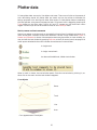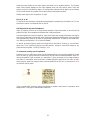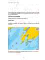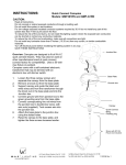
1
User manual - version 4.1, 7/6-2002
Olex AS
Postboks 1256 Pirsenteret
N-7462 Trondheim
Norway
Tlf: +47 73 54 61 99
Fax: +47 73 54 50 23
Email: [email protected]
www.olex.no
Index
5
INSTALLATION
5
5
5
5
6
6
6
6
6
7
7
7
7
7
8
8
8
8
8
Hardware
Software
Monitor
External instruments
Serial port pin congiguration
Printer
C-MAP charts
C-MAP chart catalogue
Subscribe or buy?
Undo chart selections
Ordering the charts
C-MAP upgrades
Check list for installing Olex on board
Power supply
GPS
The echo sounder
The Settings menu
Other settings
Maintenance
9
NORMAL OPERATION
9
9
10
10
10
10
10
11
11
12
13
14
14
15
15
15
15
15
16
18
18
18
19
19
20
20
20
20
20
Power on and off
How to power off
Mouse operation: Methods and vocabulary
To zoom in and out
To touch something with the mouse
To select an object
To grab an object
To make selections in menus and dialogue windows
Night screen settings
Main screen
The main menu
Ship and chart orientation
Keep this or Go back
Rotating the map
Scrolling the map - three different methods
Zooming in and out
Buttons for zooming in and out on the chart orientation control panel
Zooming by pressing the main menu scale indicator
ARPA
Automatic steering system
Waypoint arrival times displayed
Gyro compass
More accurate seafloor mapping
True heading
Roll and pitch
Magnetic compass
Adjusting the magnetic heading
Gyro compass heading has first priority
Water temperature
1
21
22
22
22
22
23
23
23
24
Vector chart data
Various functions
Tide calculation
Continuous range arrow
Utilizing private marks to find a given position
Animated lights
Continuously updated ship position
Overview map
No depths below ...
25
PLOTTER DATA
25
25
26
26
26
26
27
27
28
28
28
29
29
29
29
30
30
30
30
30
31
31
31
31
32
32
32
32
33
33
33
Marks, names and text comments
Line objects
Display various kinds of plotter data
Visible plot layers
Private plotter data layers
Default settings for new data ...
Assigning labels to plot layers
Create private plotter data
Edit control panel
Single marks
Create a new mark
To modify an existing mark
Three ways of changing status from "chosen" to "not chosen"
To delete a mark
Event mark and Man over board
Anonymous and unimportant marks
Delete all anonymous and unimportant marks
Line objects
To create a route
Converting past trips to routes
Editing an existing route
To delete a route
Tracks
Lines
Areas
To create an area
To insert marks or areas at given positions
Point and click on the position’s digits
N or S, E or W
Set the position by use of keyboard
To create an area by use of keyboard
34
SEAFLOOR MAPS
34
34
34
35
36
37
37
37
37
38
38
Enough free disk space
Good GPS position is necessary
Calculation progress information
Depth boxes
Visualizing measured depth boxes
Calculation parameters
Sounder data quality control
Upper limit of calculated depth
Tide correction
Traditional seafloor map presentation
Adjustable color scaling
2
38
38
39
40
40
41
42
43
43
43
43
43
43
44
44
44
45
46
46
47
47
48
48
49
50
51
51
51
52
52
53
53
53
54
54
54
54
Depth contours
Olex depths shown on the chart
Relief
Isometric 3D
X-buttons
Perspective 3D
Positioning the camera
Manual camera control
Camera level adjustment
Preset modes
View object
Follow boat
Fullscreen
Bottom zoom
Zoom depth by Chosen mark
Manual zoom depth adjustment
Depth below own vessel as zoom depth
No other depth data
No bottom zoom point
Profile
Dynamic scaling of the profile graph
Create a mark by clicking on the profile
Adjusting the profile’s coordinates
Path planning
Water and sub-bottom volume calculation
How to avoid incorrect depth measurements
Typical echo sounder malfunction
Sound velocity
Removing incorrect depth measurements
To delete a single depth
To delete two or more depths at a time
Delete measurements along the trip
Delete measurements by using Bottom zoom in combination with an area
Automatic search for suspicious depth data
Factor
Pyramidic
Two-sided sum
55
PAST TRIPS
55
55
55
55
55
56
56
56
56
56
Show trip on map
Rescale according to trip
Make route from trip
Delete measurements along the trip
New trips are started automatically
Terminate this trip and start another
Another trip in this area
Previous trip and Next trip
Current trip
Ship symbol
57
IMPORT AND EXPORT OF DATA AND PROGRAMS
57
57
58
58
Exporting seafloor data
Importing seafloor data
Importing pre-calculated Olex bottom charts
Exchanging plotter data
3
58
58
58
Olex upgrades
Print screen
No printer connected
59
SEAFLOOR HARDNESS WITH SIMRAD ES60
60
60
60
60
61
62
62
63
63
64
65
66
67
Installation
How to install the network card in Olex
How to configure the transducer depth
How to configure BI500 in the ES60
Testing the system
Onscreen echogram window
Depth scale
Review old data
Gain
Transducer data
Bottom discrimination
Adjusting the hardness color scale
Successful mapping
4
Installation
Hardware
The computer should be securely mounted in the wheelhouse, preferably connected to a non
interruptible power supply. Never turn the system off using the power switch, instead use
the option Power off on the Settings menu. If the computer is suddenly shut down while
running, it may cause damage to the depth data. The Olex operator should therefore regularly make backup copies of depth data as well as marks and routes.
Software
The computer is delivered ready to run with software pre-installed. The system runs on the
Linux operating system.
Monitor
The computer is set to run a monitor that can do 1024x768 pixels at 70Hz. The monitor
may be of any size, deep or flat. Other resolutions may be used, but this must be configured
by the dealer.
External instruments
The computer listens for data on all serial ports. It does not matter what instrument is connected to which port. The table below shows the NMEA sentences expected for the various
functions; for example, course can be given either by RMC or VTG. Note that in absence of
RMC and VTG, the system will calculate speed and course from progressive geographical
positions.
The data flow can be inspected by selecting Layers -> Show data flow...
Clock
Position
Course
Speed
Heading
Depth
ARPA
Autopilot
RMC
GGA
RMC
RMC
HDT
DPT
TTM
RMB
PSIMSSB @IITPT
ZDA
PSIMGPS
VTG
VTG
OSD
DBS
APB
PSIMS1
HDM
DBT
PSIMSNS
HPR400
Trawl
Temperature
MTW
PSIMS2
PTSAL
Heading, roll and pitch from the Furuno Satellite Compass SC 60: PFEC,GPatt
Heading, roll and pitch from the JRC Satellite Compass JLR-10: PJRCD,GP,5
From the HPR400, the sentence PSIMSSB contains the information of the tracking of the
underwater target. PSIMSNS gives the ship’s own gyro course collected from the HPR.
PSIMGPS is equivalent to GGA.
The RMB and APB sentences are emitted on all serial ports when the Autonav function is
enabled.
5
Serial port pin configuration
On a 9 pin serial port, pin 2 transfers data from the instrument to the computer, and pin 3
transfers data from the computer to the instrument. Pin 5 is 0V.
On a 25 pin serial port, pin 3 transfers data from the instrument to the computer, and pin 2
transfers data from the computer to the instrument. Pin 7 is 0V.
Printer
The Olex system can print screen dumps. The printer must be supported by Linux, and is
preferably installed by the dealer. Note that screen dumps can also be stored on diskettes
for printing or processing on another computer.
C-MAP charts
These charts cover the whole world, and are distributed on CDROM. The format is CM93.
Low resolution charts for orientation are pre-installed on the system, and navigation charts
may be ordered using the pre-installed C-MAP catalogue. When ordering charts with the
catalogue, be sure to have the CDROM from C-MAP in the CD drive.
C-MAP chart catalogue
From the Layers menu, select Maps from C-map, Auto chart selection and C-map chart
catalogue. The chart catalogue panel will appear in the lower left corner.
•
•
•
•
Next
Enable
Disable
Reset
Scrolls through the possible chart selections in the catalogue.
Zone, area or cell shown with brown frame is selected for ordering.
Zone, area or cell in yellow frame is removed from the order.
All selected charts are removed from the order.
Subscribe or buy?
Zoom out in order to see all of the wanted chart areas onscreen. Start the process by selecting between subscribing to whole zones or buying selected areas. If there is only one allowed choice, then there is already an existing selection of zones or areas from a previous
search. In such a case, press Disable to remove these. In this example, Buy selected areas
is selected. The following procedure is similar regardless of selecting zones or areas.
Press Next... to scroll through the catalogue. A brown frame will indicate the area, while
the area’s number is expressed on the panel. Continue to press Next... until you get the
6
area you want. Press Enable to select the area for ordering. The frame will change color
and will remain on the chart.
Several areas can be selected for ordering at the same time. Continue to press Next... and
use the same procedure as described above. The selected areas will remain with yellow
frames on the chart.
Undo chart selections
To remove an area from the order, press Next... until the actual area gets a yellow frame.
Then select Disable. Reset will remove all selected areas.
Ordering the charts
The C-MAP CD must be placed in the computer’s CD drive. The CD’s archive number must
be available. Select Order the charts. Confirm with "yes" to the check question. A user code
appears on the catalogue panel. This code must be given to the supplier of the charts, who
will return an authorization code. This can be done by telephone.
The authorization code is typed in the code form field. Then select Accept codes. If the code
was correct, the message "Successful authorization" will appear.
Then the computer will ask whether you want to continue to load the charts from the CD. It
is recommended to accept this, to actually load the ordered charts from the CD. If you answer "no", or the loading is aborted, you can later select Read data and software from
CDROM on the Settings menu to complete loading the charts. The CD from C-MAP must be
placed in the computer. It is not necessary to repeat the whole ordering process.
If you instead answer "yes", the computer will start to load the ordered charts from the CD.
A message window will show the progress. This process can last for a while, but the computer can be used as normal.
The message window shows that the system is loading the chart data from the C-MAP CD
C-MAP upgrades
Put the new C-MAP CDROM in the CD drive. Choose Settings -> Read data and software
from CDROM. The new charts automatically replaces the old ones. If the serial number on
the new CD differs from that on the old one, a new authorization code will be needed.
After upgrading Olex, reading data from the C-MAP CDROM may be required. Choose Settings -> Read data and software from CDROM. If needed, Olex will download the necessary
data.
Check list for installing Olex on board
Power supply
It is important for the computer to have a non interruptible power supply. If the computer
suffers a power loss while calculating seafloor maps, some depth data in the area being calculated can be lost. Typical evidence of loss of power is rectangular areas with missing
depth data and seafloor maps at certain zoom levels. When the computer is restarted after
a power loss, it will undergo a file system check, which may delay start-up.
Short power losses can appear when changing between ship’s power and land power. A solution to such problems may be installing an UPS; Uninterrupted Power Supply.
7
Another way of protecting the system from electrical noise is to install so called optical connections between the computer and the external instruments.
GPS
The GPS antennae should be mounted as low as possible to reduce movements when the
ship is in heavy seas. On the monitor, such movements will show as unsteady ship movement with unstable course and therefore an unstable chart screen.
The GPS antennae should also be placed with most free sight in all directions. A compromise between the two demands would be a good solution.
The GPS must be set to broadcast the NMEA sentence GGA. It should also broadcast RMC
which contains the course, speed, time and date. The time must be expressed as UTC in order for the tide calculation and onscreen clock to work correctly. Time may also be expressed by the ZDA message. If RMC is not available, a second best solution is to use VTG.
This may, however, cause the tide calculation to fail.
The echo sounder
Always set the transducer’s depth below sea surface, both at the sounder and at the Olex.
The system will then find out whether the sounder is adjusting for transducer depth or not.
If possible, the sound velocity should be set to 1500 m/s.
The Settings menu - initial permanent settings
The upper part of the menu shows information such as system type, the system’s serial
number, software version and free disk space.
Some settings are permanent. These are the settings on the upper part of the menu. Press
Edit to activate the Settings buttons. Set the length and width of the ship, and the location
of the GPS and the echo sounder transducer. Set the correct local offset from UTC. Remember to adjust the offset when turning from winter to summer time. The GPS ought to express the time as UTC by RMC or ZDA messages in order for the onscreen clock to be exact.
Other settings
•
•
•
•
•
•
•
Course line: Sets the fixed distance of the ship symbol’s course line.
From meters to nautical miles: Decides at what range a distance should be expressed as nautical miles instead of meters.
No depths below: Gives the opportunity to select a threshold depth for depth numbers
to be shown on the chart.
Size of ship symbol: Choose between a Small, Medium or Large ship symbol.
Switching to next waypoint in autonav: By selecting Auto, Olex will force the autopilot to start the turn automatically when reaching the waypoint. If this is not preferred, then select Manual.
Depths and heights shown as: Choose between Feet, Meters and Fathoms.
Language: Choose between Norwegian, English, Spanish, French and Icelandic.
Maintenance
During start-up, a grey screen will appear with some copyright information. By pressing
Maintenance a new screen will appear with a terminal window which gives access to the
operating system and the Olex files. To return from this screen to Olex, simply type the
command "reboot" in the terminal window, then press Return. Remember to point the
marker arrow in the window to activate it.
8
Normal operation
All functions are operated by mouse. The keyboard is used only when writing comments
along with marks, or to set event marks. The menus and other functions are activated by
mouse. All buttons are radio buttons. Some of the buttons activates a service when pressed,
and deactivate when depressed. Radio button labels are in red fonts in this manual.
A service button. The service is active as long as the button is pressed.
Push buttons
There are three menus offering a series of options and settings. In addition, there are dialogue windows which appear when needed. If a service is not available, it is indicated by
the text of the button turning grey instead of black, and the button becomes almost invisible. As an example, the main menu buttons Bottom and Boxes will fade when the seafloor
map is disabled.
The philosophy is that the system should be automatic, with as little manual operation as
possible. Using the control panel at the upper left corner, it is possible to set a fixed chart
scale, placement of ship, and orientation of the chart. The settings will automatically be reestablished after temporary changes, as when zooming in at some interesting point 100
nautical miles from the ship. This way the settings are preserved and the ship will always
be shown on the screen.
Power on and off
The computer often have a main power switch which must be switched on. The computer is
then started by pressing the On/Off button. Then a start-up sequence follows with lots of
uninteresting text passing by on a black background. Then the screen turns grey with a
text window with some copyright information. Press OK or wait for 30 seconds, and the
Olex system will start. Do not turn off the computer during start-up, this can severely damage the computer. See the previous page about the Maintenance option.
How to power off
Always shut down the computer by selecting Settings -> Power off. Never turn off the computer in any other way. Depth data and chart files may be damaged or lost.
•
•
•
•
Press Settings in the upper left corner. The menu appears.
Select Power off, at the very bottom of the menu.
Confirm your action.
Wait for the computer to turn itself off.
9
Mouse operation: Methods and vocabulary
Three button mouse without rollerball
Certain terms and expressions are used to describe the use of the mouse. A list of the most
common expressions together with the methods of operation is given below.
To zoom in and out
The marker is placed at the zoom point. Press the left mouse button to zoom in, and the
right mouse button to zoom out. By moving the mouse while zooming, the zooming point
can be moved to a preferred position on the screen.
To touch something with the mouse
In order to be able to press, grab or select something, it must first be touched by the mouse.
The touching is confirmed by the object changing color, as described below. The color
change indicates that the object can be selected, grabbed or edited.
•
•
•
•
When the marker is placed on a button, the button will get red text and a red frame. It
is touched, and can be pressed with the left mouse button.
A private plotter object will highlight when touched, and the color changes to yellow.
The object can now be selected or grabbed. The same goes for recorded tracks, lines,
routes and areas.
Other objects, like ARPA targets and the 3D camera, will also highlight when touched.
The direction indicator arrow in the upper left corner will highlight, and a set of buttons will appear when the mouse is touching this particular area of the screen.
To select an object
An object is selected by clicking on it. Often some information is shown. If you select a private plotter object, such as a wreck symbol, the name, position and distance from ship to object will be shown on the Chosen object control panel that appears on the right side of the
screen.
To grab an object
To move an object, it must first be grabbed. Start with touching the object. Then press the
left mouse button, and keep it in. The object is now grabbed, and can be moved by moving
the mouse. The moment the left mouse button is no longer pressed, the object is released.
10
•
•
•
Grab the object symbol on the main menu and drop it somewhere on the chart.
Grab the direction indicator arrow in the control panel in the upper left corner, turn it
and release.
With the centre mouse button (or by pressing both buttons simultaneously on a
2-button mouse) you can grab the chart itself, to move it in any direction. The marker
arrow changes to an anchor symbol when the chart is grabbed like this.
To make selections in menus and dialogue windows
If this manual says "Select Layers -> Planned routes" it means that the button Layers on
the main menu should be pressed. To press the button, touch the button with the mouse
and press the left mouse button once. Then the Layers menu will appear. Then press the
button Planned routes.
Night screen settings
The brightness of the monitor should always be adjusted with the dimmer function. The
dimmer panel appears when the marker touches the sun symbol in the upper right corner.
Adjust the brightness by moving the bar, or choose between fixed night and day colors.
When the monitor is fully dimmed, the sun symbol will still be visible, and is easily reached
by moving the marker upwards along the edge of the screen.
Dimmer control panel
Note that a typical flat TFT monitor cannot be fully dimmed, since there will always be
some background light from the screen. For vessels where the night bridge environment are
important, a CRT monitor or a special adjustable TFT screen should be used.
When using night screen settings, there is not enough colors available for showing the seafloor map in 2D. Use 3D, of very dimmed daylight colors. Anyhow, the calculation is not
affected by this.
11
Main screen
The ship is shown with course line ahead and the present trip displayed behind. Also
shown are a route, a recorded track and a mark. Other items presented on the screen:
•
•
•
•
•
•
•
•
•
•
•
•
Direction arrow: In the upper left corner, pointing towards the north. Normally, the
arrow is shown while the rest of the panel with buttons for configuring the orientation
of both ship and map, is hidden. Touch the area to make the panel appear. See page 14.
Keep this: The ship and chart setting set on the control panel is ignored, and can be
adjusted manually.
Go back: The ship and map settings return to those set on the control panel.
GPS window: In the upper right corner. Displays position, course, speed and GPS status. Red colored digits means the position quality is not good enough for seafloor mapping.
Echo sounder window: Underneath the GPS window. Displays the depth given by
the echo sounder. If there is no data input from the sounder, the window disappears.
Tide window: Shows the tidal curve, along with time for high and low water for the
nearest reference port.
Chosen mark control panel: The panel appears when a mark is selected. Contains
buttons for editing objects, and the Autonav button.
Night dimming of the monitor: A control panel appears when touching the sun symbol in the upper right corner.
Autonav window: Appears when Autonav is enabled for a route or mark.
Overview map: Displays an overview map, and indicates the general area of the chart
on the main screen.
Depth contours: In the lower left corner, for setting the equidistance.
Plot layers: In the lower left corner. Allows for turning on and off the display of different plot layers.
12
The main menu
At the top of the screen is the main menu. The menu bar contains the following buttons and
options:
•
Settings
Shows the Settings menu
•
Past trips
Shows the Past trips menu
•
Layers
Shows the Layers menu
•
3D
Turns on the 3D display
•
•
A mark which can be grabbed and placed to form an object
Mark
Puts a mark on the chart at the ship’s current position (not with
HT)
•
Track
Initializes and ends the recording of a track
•
Hardness
Turns on and off the hardness colors (with HT only)
•
Bottom
Turns on and off the bottom zoom function
•
Profile
Turns on and off the seafloor profile function
•
Echo
Turns on and off the display of the echogram (with HT only)
•
The chart scale
•
Buttons for adjusting the color scale of the seafloor map
•
Relief
Turns on and off the relief display of the seafloor
•
Boxes
Makes the measured depth boxes turn red
•
Print
Creates and saves screenshots and prints them if a printer is
present
•
Shows the control panel for night dimming when touched
"With HT only" means that the system is equipped with the software package for seafloor
discrimination. See the chapter "Seafloor discrimination with Simrad ES60" for further details.
13
Ship and chart orientation
The control panel can be used to configure the orientation of both ship and chart on the
screen. To display the buttons, simply touch the area with the mouse.
The panel appears
when touched. North
and Edge chosen.
•
•
North
Course
•
Jump
•
Center
•
Edge
The Edge modus is
set.
Neither Jump, Center nor Edge are
set.
The chart is set with north up.
The chart is set with the ship’s course up. The arrow points towards the
north.
The ship is travelling across the screen. When reaching the edge, the whole
chart will move to an edge so that most of the chart is ahead of the ship.
The ship is always at the centre of the screen, the chart is continuously
moving.
The ship is always nearby the edge of the screen; which edge depends on the
ship’s course.
On slower computers with a lack of RAM, some functions like the calculation of the seafloor
and zooming in and out will be slower. Choosing the Jump setting will help.
With neither Jump, Center nor Edge activated, the vessel will eventually move outside of
the area displayed on the screen. Hitting any of the three keys will instantly make the vessel reappear.
Keep this or Go back
The control panel allows for preset modes to be set. One of the lower three buttons on the
control panel will be activated indicating the setting. When a preset mode is chosen, one
can still adjust the chart display by zooming in and out or scrolling, as described later. Such
adjustments will be of intermediate character only. The buttons Keep this and Go back will
appear just below the main menu. After 15 seconds with no further operation, Olex will go
back to the preset mode.
Press Keep this to deactivate the preset modes or press Go back to instantly go back.
14
Rotating the map
Grab the orientation arrow to rotate the map. Names and depths will not rotate along with
the map. Rotating the map is useful especially when working with Isometric 3D.
Scrolling the map - three different methods
•
•
•
Using the mouse, grab the map by pressing the center button. Drag the map in any direction. On a two button mouse, press both buttons simultaneously to achieve this.
Scroll sideways or up and down by pressing the keyboard’s arrow keys.
First press the center button and hold. Then press any of the other two buttons and
hold. A red circle appears. Now move the mouse away from the circle. The map scrolls
in the opposite direction. The scroll rate corresponds with the mouse’s distance from the
center of the circle.
Zooming in and out
Zooming in and out is done by simply pointing the mouse somewhere on the chart and
pressing the left or right button. Hold the button to continuously zoom in or out around the
pointer. Scroll the chart while zooming by moving the mouse around the screen.
If either Jump, Center or Edge are activated on the control panel, the Keep this and Go
back buttons will appear.
Buttons for zooming in and out on the chart orientation control panel
Press the In or Out buttons on the control panel to zoom in or out around the vessel, thus
changing the preset scale. The Keep this and Go back buttons will not appear.
Zooming by pressing the main menu scale indicator
Pressing the scale indicator on the main menu with either the left or right mouse button
changes the preset scale.
Should the vessel be in a position not displayed on the screen, pressing the scale indicator
will zoom in or out around the center of the screen instead of around the vessel.
15
ARPA
Olex will show ARPA radar targets as triangular symbols. Each target gets an ID supplied
by the radar. The target’s color indicates it’s status; grey means that the position is unreliable while red indicates a good fix. When the marker touches the target a panel will appear
showing the target’s course and speed, along with it’s distance from own ship.
ARPA-target, unreliable position
ARPA-target, good position
When touched, the target turns yellow and a panel appears. Click
on the panel to make it stay.
The panel stays. A new click on the panel makes it disappear.
The panel, when touched, will display the buttons Name and
Track. Click on Name to get the panel pictured below, allowing for
naming the ARPA target.
Name the ARPA target by using the keyboard. Finish by pressing Ok.
16
The target’s name now appears on the panel. Click on the panel to
hide it.
The given name is shown together with the target. Click on the
target to make the panel reappear.
Touch the panel for the buttons Name and Track to appear. Push
Track to start logging the target’s track line. The track line’s
starting mark will get the same name as the target. The Track
button remains visible while activated. Click on the panel to hide
it.
The logged track line does not show, because the corresponding
plot layer has been turned off. A red frame indicates that the
track line is being logged, even if it does not show.
The plot layer containing the track line has been turned on.
Choose the track line by clicking
on it. The corresponding Chosen
track panel now displays the
target’s name.
On the Layers menu, Present trip has been
turned on. A brownish line shows the target’s
trip, but only as long as the target is locked by
the radar.
17
Automatic steering system
Connected to an automatic steering system, Olex will navigate towards a chosen mark or
along line objects. This is called Autonav. Choose a mark or a route and press Autonav, one
of the four buttons on the Chosen object control panel (see page 27). Olex will then start
transmitting the necessary messages to the automatic steering system. Useful navigational
information is displayed in the Autonav window.
Waypoint arrival times displayed
Navigating along a route using Autonav, waypoints which are named will be displayed
along with estimated arrival times on a separate panel on the left part of the screen. Some
of the waypoints may represent ports where the vessel are to stop for a while. The duration
of these stops may be taken into account when calculating arrival times. For this to take
place the estimated delays must be mentioned along with the waypoint’s name using the
following syntax: Harbourname (12 minutes). The estimated arrival times are continuously
recalculated, based on the vessel’s speed at the moment.
Arrival times displayed, named waypoints only
Gyro compass
A gyro compass connection will supply Olex with information about the vessel’s heading.
The heading is indicated by a stippled line attached to the ship symbol. The ship symbol itself will also be rotated according to heading. The continuous line shows the vessel’s course
over ground as computed by the GPS.
More accurate seafloor mapping
The echo sounder’s position relative to the GPS antennae is more easily determined when
the heading is known, especially when there is a significant distance between the antennae
18
and the sounder. Correct positioning of the soundings is possible for example when the vessel lies still or is drifting sideways.
The stippled line represents the heading
True heading
A small window on the lower left part of the screen shows the heading. The vessel’s course
over ground is displayed in the GPS window in the upper right corner.
The ship is drifting sideways. The ship is shown in true scale when zooming in sufficiently.
19
Roll and pitch
If the system receives pitch and roll messages the option Show roll and pitch will appear on
the Settings menu. When activated, a window showing roll and pitch will appear.
Above the ship symbols real time values are shown while averaged values together with the
vessel’s speed are shown below
Magnetic compass
If Olex gets information about magnetic heading from a magnetic compass, the heading
panel will display the text "Magnetic heading" together with the corresponding value.
Apart from this, the functionality is the same as for the gyro compass.
Adjusting the magnetic heading
By pressing the Adjust button on the heading panel, a new panel appears, allowing for the
adjustment of the difference between magnetic and true heading. Finish by pressing Ok.
Gyro compass heading has first priority
When both gyro compass and magnetic compass are sending heading messages to Olex, the
gyro compass heading will be used. Only when there is no gyro compass messages will the
magnetic heading come into use.
Water temperature
Some transducers have temperature sensors. The surface water temperature will then be
displayed on a panel in the lower left part of the screen.
The temperature is shown on this panel
By pressing the button Plot on the water temperature panel, a colored temperature track
line will appear. The coldest part of the track shown will be blue while the hottest is red,
20
making for a dynamic color scale. The lowest and the highest temperature values can be
seen on both sides of the color palette.
The button Plot is pressed. A temperature scale and a Values button appears.
When Values is pressed the measured temperature is displayed at intervals along the track.
Vector chart data
On the Layers menu one will find the label "Vector chart data". Different layers of information can be turned on or off.
Certain parts of the world may be covered by charts based upon paper charts with unknown datum. If such an area is displayed the text "Unknown Chart Datum" will appear
in red on the upper part of the screen. This will also be the case for some C-MAP demo
charts.
Options to be found on the Layers menu, labeled "Vector Chart Data":
•
•
•
•
•
•
•
•
•
•
•
•
•
Symbol texts: Displays lighthouse names and the like.
Texts and names: Displays all other texts and names.
Depths and elevation: Displays vector chart depths, bridge clearances and such.
Pipelines, submarine cables
Restricted areas
Various symbols: Such as shipwrecks and churches.
Economic and political borders
Navigation lines, ferry routes
Norwegian fisheries database shoreline
Depth contours, seabed types: Displays the mentioned vector chart data.
Depth areas: Activates the coloring of depth areas deeper than 10 meters. More shallow
areas are always colored.
Lights and light sectors
- and their sector lines
21
Various functions
Tide calculation
Settings -> Adjust bottom calculation for tide level activates the function. It should always
be on, except when operating in freshwater locations such as lakes or rivers. When the
function is not on, a warning in red reading "No tide level adjustment" will stay permanently on the screen. The tide calculation is based upon historical data collected during the
last 30 years. Olex automatically chooses the nearest tide reference port. Far at sea, exceeding the maximum distance to the nearest reference port, the tide calculation turns itself off.
Make sure that Olex gets the time and date right. Preferably, these data should come from
the GPS. The GPS must be set to give out the RMC message. If the time is not right, the
tide calculation will fail.
The tide calculation window
Three different tidal levels are indicated to the left of the vertical bar. All values are relative to the lowest tidal level that may appear.
•
•
•
The value given at the top of the bar is the nearest high tide level.
Shown in a bigger font, the center value refers to the level at the moment.
The lower value is the nearest low tide level.
The red bar indicates the present situation. Below the curve are given the low and high tide
times.
Continuous range arrow
The function can be found on the Layers menu. An information window will appear and
place itself beneath the tide calculation window.
The arrow’s position is shown together with distance and bearing from own ship
Utilizing private marks to find a given position
A simple way of finding a given position is to place a private mark on the position. As soon
as the given position is entered onto the Chosen mark control panel, Olex will display the
position centered on the screen. Distance and bearing from own vessel along with ETA are
displayed on the control panel.
This option will make the lights appear in yellow, green or red, the light sector in which the
vessel is positioned determining the color. Also the lights will blink according to their characteristics, provided this information is encoded in the vector charts. Only the lights
22
believed to be visible from the vessel will be animated. Animated lights are found on the
Layers menu, under "Miscellaneous information".
Continuously updated ship position
The function is designed for fast moving vessels. Based on the last known position and
course Olex will continuously calculate and update the vessel’s position in between the GPS
given positions. This makes for a smooth movement, and a slightly more accurate positioning of the vessel on average.
Since this function demands a lot of computer RAM it is automatically turned off when bottom calculation takes place.
Overview map
This option is found on Settings -> Show movable overview map. The screen boundaries are
shown as a rectangle, the grey side of the rectangle being the upper screen edge. Click anywhere in the overview map and the position will be centered on the screen.
23
No depths below ...
This option on the Settings menu allows for certain depths to be suppressed from being displayed. Only depths more shallow than the chosen value will be shown. To see all depths,
choose Disabled.
The setting "No depths below" 10m has been chosen on the Settings menu
24
Plotter data
Private plotter data are marks, line objects and areas. There are no limits to the amount of
such data being stored. All plotter data are saved, and can be written to diskettes for
backup purposes or for sharing with other Olex owners. Private plotter data are created by
the Olex operator using mouse, keyboard or both. Ship’s own track is logged by pressing the
Track button on the main menu. ARPA, AIS and ITI targets can also have their tracks
logged. Previous trips can be converted to routes on the Past trips menu.
Marks, names and text comments
Marks may appear as single marks or connected by lines to form line objects and areas. Any
mark can be given a name or a short text comment. The text is only visible when Layers ->
Names and comments is chosen. More extensive texts may be written to a text window. Access and edit the text window by pressing Edit text on the Edit control panel, see page 28. A
small square attached to the mark indicates the existence of a text window.
A single mark
A single, named mark
As above with additional, hidden text window
When a mark is chosen, the text window opens. Close the text window by clicking it; another click on the mark and the text window reappears.
Line objects
Route
Track
Line
Area
Four appearances of line objects
25
Display various kinds of plotter data
In previous Olex versions the plotter objects were divided into Marks, Routes, Tracks, Lines
and Areas. The display of each of these five categories could be turned on or off on the Layers menu. Should Olex contain plotter data in the old format, the Layers menu will have
the necessary check boxes for turning on and off the five categories in the old fashioned
way.
Olex contains plotter data in the old
format
All the plotter data are in the new
format
In order to see only a certain object among many in a specific plot layer, choose the desired
object by clicking on it. Then turn off the display of the plot layer. The chosen object will remain visible onscreen.
Visible plot layers ...
Turn on Visible plot layers ... on the Layers menu. A bar with ten buttons will appear on
the lowermost part of the screen. The buttons are used for turning on and off the 10 plot
layers. Be aware that when creating an object, the corresponding plot layer automatically
turns itself on.
Buttons for turning on and off the 10 plot layers
Private plotter data layers
Any plotter object must have at least one plot layer assigned to it. An important mark, for
instance, may have all 10 layers assigned to it and will thus be visible no matter which
layer is turned on. Names are given to the plot layers by the Olex operator. The names may
be changed at any given time, as can plot layer assignment to plotter data.
Default settings for new data ...
To be found on the Layers menu. A control panel appears which allows for setting default
plot layers for new plotter data. The picture on the following page shows the control panel
with default factory settings, ready to be modified by the Olex operator.
26
Factory settings to be modified by the Olex operator
Assigning labels to plot layers
Turn on Visible plot layers ... on the Layers menu. Right-click the A button on the plot
layer selection bar. Replace the A with a suitable plot layer name in the "New name" box
that appears. Finish by pressing Ok or hit the Return key. The corresponding button in the
Default layers box will now have the new plot layer’s name. The plot layers can be renamed
at any given time.
Use the backspace key to remove the letter A before typing the new label
User defined labels have been given to these plot layers
Create private plotter data
When creating or choosing any plotter object the Chosen object control panel appears as
shown below, offering various types of information related to the object.
A single mark
Planned route
Starting automatic navigation towards the mark.
Rearranges the chart in order to center the object on the screen.
27
To modify the object’s parameters, press Edit. Depressing Edit leaves the
object chosen.
Change status from "chosen" to "not chosen".
Edit control panel
The Edit control panel will appear whenever an object is being modified. It allows for modification of position, name, plot layer assignment and other properties. Depress Edit to close
the Edit control panel.
Single mark Edit control panel; the buttons related to line objects are deactivated
Single marks
A mark is defined by a symbol at a certain geographical position; it may be given a name or
a multiple line text comment. All marks have a timestamp, showing the date of creation or
the last modification date. Choose between 24 different symbols to define the mark.
Create a new mark
1. Zoom in until the main menu scale is 2nm or less.
2. Grab the mark symbol
on the main menu and drop it somewhere. Both the Chosen
mark control panel and the Edit control panel appears. If needed, grab the mark again
to position it.
3. Choose one of the symbols on the Edit control panel.
4. Assign one or more of the plot layers to the mark, or accept the default setting.
5. Add a name or comment by typing in the white field. The name will appear to the right
of the mark provided Layers-> Names and comments are activated.
6. Lengthy comments may be added by first clicking Edit text on the Edit control box. A
writing pad appears. Use the arrow keys or mouse pointer to move the cursor while editing.
7. Press Finish on the Chosen mark control panel to finish.
28
To modify an existing mark
1. Choose the mark by clicking on it. A grey frame surrounds the mark and the Chosen
mark control panel appears.
2. Press Edit. The surrounding frame turns red. The Edit control panel appears.
3. When finished modifying the mark, depress Edit or press Finish.
A chosen mark, before pressing Edit
One may also choose a mark by double-clicking it.
Three ways of changing status from "chosen" to "not chosen"
•
•
•
A chosen mark becomes "not chosen" by clicking it once with the left mouse button.
Press Finish on the control panel.
Choose another object. This object now becomes chosen instead of the previous one.
Not chosen
Chosen
Chosen and editable
To delete a mark
Choose the mark by clicking on it, then press Edit on the Chosen mark control panel. Press
Delete mark on the Edit control panel. Olex will ask for confirmation before deleting, except
for anonymous, unimportant or very recently created or modified marks.
Triple-clicking the mark is another way of deleting it. Practicing may be necessary.
Event mark and Man over board
Press Mark on the main menu or press any key to instantly produce an Event mark on the
vessel’s present position. The Chosen mark control panel, appearing automatically, offers
navigational information.
29
Anonymous and unimportant marks
Marks with symbols as shown below are considered unimportant and anonymous provided
no comments are added to them and as long as they are single marks and not part of a
track, line or such. Anonymous marks are the easiest to create.
Anonymous marks
Delete all anonymous and unimportant marks
All such marks can be deleted in a single operation by choosing Settings -> Delete all
anonymous and unimportant marks.
Line objects
Planned routes, tracks and lines are different types of line objects. Basically they are all
handled the same way.
Line objects consists of two or more marks tied together by straight lines. The line between
the marks are given a color of choice. The marks may also be called waypoints. There are no
limits to the number of marks or the total length of a line object.
A planned route as well as any of the other three line objects has a direction determined by
the order of waypoints set. The direction may be reversed by clicking Reverse course on the
Edit control panel. When making a route or any other line object, marks grabbed from the
main menu are added to the end of the route. To add marks at the start end click Reverse
course first.
Line objects are named by their first or their last mark, or both. Typical line objects are
planned routes and recorded tracks. Line objects may be used for measuring distances, defining profile lines or to indicate borders of various kinds.
To create a route
1. Start by creating a single mark as described earlier.
2. While the mark is still in Edit mode, grab another mark from the main menu. A line
connects the two marks to form a route.
3. Add more marks to the route by grabbing them from the main menu or create new ones
by grabbing and dragging the line between the marks.
4. To choose a color, click the according buttons on the Edit control panel.
5. Assign one or more of the plot layers to the route.
6. Delete single marks by clicking Delete mark.
7. Name the route by giving names to it’s first and/or it’s last mark.
8. Conclude by clicking Finish on the Chosen mark control panel.
Converting past trips to routes
Past trips chosen on the Past trips menu may be converted into routes with the
Past trips -> Make route from trip function. The waypoint density will vary along the route,
depending on it’s complexity. The route can be edited as can any other line object.
30
Editing an existing route
1. Choose the route by clicking on it. The route starts pulsating so as to stand out amongst
other objects.
2. Click Edit on the Chosen route control panel to switch to edit mode.
3. After editing, close the Edit control panel by pressing Edit or Finish on the Chosen
route control panel.
The Edit control panel as presented when the mark is part of a route
To delete a route
1. Choose the route by clicking on it.
2. Click Edit on the Chosen mark control panel to switch to edit mode.
3. Click Delete all.
4. Confirm by clicking "yes" if prompted.
Tracks
To start recording a track line from the ship press Track on the main menu. This will put a
one-flag mark at the starting point. To end the track simply deactivate the Track button.
This will put a two-flag mark at the end of the track line. Such track lines can be edited in
the usual manner, they are no different from other line objects.
To check if a track has been edited, check the timestamp of the various marks.
Other ship’s tracks may be saved if an ARPA radar is connected to Olex.
Lines
A line is created the same way as a navigation route, but is renamed a line on the Edit control panel. Normally it’s waypoints are not visible.
1. Start by creating a route as described earlier.
2. While in Edit mode press Line on the Edit control panel.
3. Finish by clicking Finish.
31
Areas
An area is a line where the first and last marks are connected. The area will be filled with a
translucent color of choice, allowing chart details covered by the area to be seen.
To create an area
1. Start by creating a route as previously described.
2. While still in edit mode press Area on the Edit control panel. The first and last marks
are automatically connected.
3. Select the preferred color.
4. Finish as usual by pressing Finish.
The unfinished area "Torsk"
Finished area
Choose an area by clicking one of it’s sides. Press Edit to modify it’s line segments, add
more bends or change the color.
To insert marks or areas at given positions
Various methods may be used in order to create objects at given positions. A few examples
are given below.
Point and click on the position’s digits
•
Click left button to increase
•
Click right button to decrease
The Chosen mark control panel
32
Grab the mark symbol on the main menu and leave it at a random position. The Chosen
mark control panel appears to the right together with the Edit control panel. Place the
marker on any of the position digits. An orange field indicates which digit may be altered.
Click the left button to increase or the right button to decrease the value.
Modify more digits until the position is right.
N or S, E or W
To the left of the latitude is indicated the hemisphere in question by the letter N or S. Click
the letter to switch. Do likewise with E and W.
Set the position by use of keyboard
Start by creating a mark as in the previous example. Place the marker on the first of the
position’s digits. An orange field indicates that it may be altered.
Use the keyboard to insert the position. After each input the orange field moves one step to
the right. All decimals must be set. After finishing the latitude modification the orange field
will automatically move on to allow for longitudal modification. Proceed in the same manner, defining all decimals. Fill inn zeros if needed.
In case of erroneous typing, move the orange field to the left by clicking, or use the backspace key. Then continue typing the correct position. Assign a name and choose an appropriate mark symbol. Finish by clicking Finish.
To create an area by use of keyboard
Positions on a list, defining an area, may be inserted one by one using the keyboard. Create
the first mark by typing onto the Chosen mark control panel as described before. After finishing the position, type a comma or a semicolon. Typing a comma at this stage creates a
new mark in connection with the former. Proceed typing the position of this mark as well,
ending with a comma as long as there are more positions on the list. In the end click Area
on the Edit control panel.
Type a comma after finishing typing the position to create a new mark in connection with
the previous. Then type in the new mark’s position.
33
Seafloor maps
Olex will automatically create seafloor maps, also called Olex charts, when it receives adequate signals from echo sounder and GPS. The calculation of the Olex chart is a continuous process and will slow down when the system is heavily used. The speed of the process
will also vary with the complexity of the seafloor data. However, all measured data are
taken into account, independent of calculation speed.
Enough free disk space
On the upper part of the Settings menu one will find information about free disk space. The
calculation process demands somewhat more space than what is needed for the calculated
Olex chart. When too little space is left the free disk space value will turn red and the calculation will stop.
Good GPS position is necessary
When the GPS position is of low quality the position will be displayed in red in the GPS
window. No measured depths will be used for calculation as long as the position is unsure.
The position is displayed in red due to low GPS position quality
Calculation progress information
A rectangle on the screen will show which areas are being calculated, and an indicator in
the upper left part of the screen shows the progress, provided the function Show calculation
progress are activated on the Settings menu. By clicking on the indicator the area calculated will be centered on the screen.
Indicator showing the progress of the calculation process
The display of the seafloor map is turned on by choosing Show calculated sea floor on the
Layers menu. Choose between traditional presentation in blue with depth contours, or the
Relief presentation suitable for the more thoroughly measured areas. Two 3D modes are
also offered.
34
White areas not yet measured. Compare with the picture on page 39.
Depth boxes
The seafloor maps are stored as a seamless carpet covering the whole world, made up of
small rectangles or depth boxes. These typically measure 5x5 meters, matching the typical
GPS accuracy. If a more accurate GPS is connected, the size of the depth boxes can be
scaled down to correspond with the GPS resolution.
Each of the depth boxes contains a depth value which is either measured or calculated, or
none. The data is shown integrated with the charts. By repeated measurements inside a
depth box, the latest one is used. Additional software lets Olex store and present other
types of data like bottom hardness. Read more about this later.
Mix of measured and calculated depth boxes.
All unmeasured boxes within a 0,3nm radius from a measured box are given a calculated
value. The radius within which depths are calculated can be adjusted as well. Contact your
local dealer for further details.
35
Visualizing measured depth boxes
The quality of the seafloor map depends on the density of measurements. The quality becomes better as more trips are made in the same area. The measured depth boxes can be
highlighted by pressing Boxes on the main menu.
Boxes activated on the main menu
3D view of the seafloor, Boxes activated.
36
Calculation parameters
There are three main settings which covers the calculation of the seafloor map. These are
found on the Settings menu.
Sounder data quality control
The first is Sea floor calculation, which can be set to Optimal, Always or Stopped. Optimal
will make Olex try to remove incorrect depth values. The measurements from the echo
sounder are scrutinized for suspect values; improbable peaks and too flat areas are ignored.
These erroneous measurements may come from air bubbles under the ship, or the sounder
"loses the bottom". Some incorrect depth values may still survive this quality check; these
can be removed manually afterwards. Always turns off this quality check. Stopped will inhibit the seafloor calculation.
Upper limit of calculated depth
The second is Calculation shallow limit. This sets the upper limit of depth values to be considered. A setting of 5 or 10 meters are recommended.
Tide correction
The third is Adjust bottom calculation for tide level. This function is explained under "Various functions" on page 22. For mapping lakes or rivers the tide correction must be turned
off. A warning reading "No Tide Calculation" will stay on the screen as long as the function
is turned off.
The message "No Tide Calculation" to the upper left warns that Settings -> Adjust bottom
calculation for tide level is turned off.
37
Traditional seafloor map presentation
As long as the Relief button on the main menu is not pressed, the blue seafloor map with
depth contours will be displayed.
Adjustable color scaling
The seafloor map is shown in hues of blue, from light blue for shallow waters to dark blue
for deep waters. The scaling can be adjusted on the main menu using the buttons pictured
below.
Detail from the main menu
Depth contours
The blue Olex chart is always shown with depth contours, except when Depths is pressed
on the Depth contours control panel in the lower left part of the screen. The equidistance is
shown on the panel. Olex automatically adjusts the equidistance to match the blue color
scaling. Manual adjustment can also be made.
The control panel allows for manual equidistance adjustment.
Olex depths shown on the chart
When zooming in sufficiently the depth of each of the depth boxes will be displayed. Measured depths are in red while calculated depths are grey. Zooming out makes the depth
boxes diminish in size on the screen until lack of space forces the depth information in the
individual boxes to be hidden.
38
When the chart is zoomed out too much for the individual depth box information to be displayed, pressing Depths on the Depth contour control panel makes Olex display the shallowest depth in the area actually covered by the displayed depth. This function is available
up to a certain scale and only with the blue Olex chart. When these depths are displayed
the depth contours are automatically turned off.
Relief
Relief mode makes the seafloor features stand out. Compare with the picture on page 35 .
Press the Relief button on the main menu to activate the function. The terrain is shown utilizing a light and shadow technique, making the finer seafloor features stand out. Relief
works best in a well surveyed area. Choose between three contrast levels using the control
panel in the lower left part of the screen.
Contrast level control panel
39
Isometric 3D
Press 3D on the main menu to activate the function. See to it that the option Layers -> New
perspective 3D is not chosen.
Isometric 3D shows the same area as is displayed in 2D. Switch between the two modes to
see the chart selection.
Most objects are retained, shadows cast on the seafloor.
The isometric 3D chart can also be arbitrary rotated: put the marker on the arrow and drag
by pressing the left mouse button and rotate the chart in the preferred direction.
Most of the functions available in the 2D view is present. Note that when placing marks
and editing line objects, the positions are set by moving the object’s anchoring point on the
seafloor.
Also note that the 3D view is expensive for the computer to handle, reducing time resources
otherwise available for seafloor calculation. This just means that it will take longer time between each seafloor update. No data is lost; the end result will still be the same.
X-buttons
Normally, the vertical scale is the same as the horizontal, giving a correct as possible understanding of the topology. However, when zoomed out the 3D view tend to be flat and featureless. The vertical scale can therefore be exaggerated by the 2X, 3X, 4X... buttons in the
upper right corner. 1X returns to true scale.
40
Perspective 3D
Pressing 3D on the main menu activates the function provided Layers -> New perspective
3D is chosen.
The function offers a fullscreen true view display of the seabed floor. A virtual camera can
be moved freely around in order to view the underwater landscape from various positions
and angles.
The 3D map may also be displayed in a separate window inside the 2D map. Then both
maps can be operated independently.
Fullscreen 3D
Like in Isometric 3D the topology can be exaggerated using X-buttons. These are found to
the upper right inside the small window or on the control panel in the lower left corner of
the fullscreen 3D.
The red color indicates the activation of the X-buttons
41
Positioning the camera
•
•
•
Zoom out to see the area to be viewed.
Choose Layers -> New perspective 3D.
Press 3D on the main menu.
A window showing a 3D chart appears. This window has its own menu bar. Start by pressing Get camera.
The camera symbol
The camera symbol will appear to the left of the 3D window, indicating the direction and
field of view. Click and drag to move the camera. Look around by scrolling the 3D map.
Watch the camera symbol rotate on the 2D map while scrolling the 3D map.
Camera symbol with dotted lines showing the field of view
42
Manual camera control
In the upper left corner of the 3D picture a camera direction arrow is found. Rotate the arrow using the mouse to rotate the camera accordingly.
The camera direction arrow, pointing eastwards
Camera direction can also be set by scrolling the 3D map using the center mouse button.
Manual camera control are possible even when a preset mode is set. The effect will be of an
intermediate character though, the camera going back to the preset mode as soon as the
manual control ceases.
Camera level adjustment
A control panel in the lower left hand corner sets the camera level. If the level is set underneath the seabed floor, the camera will position itself 20 meters above the seabed. The underwater landscape is best viewed from somewhere above the surface.
Camera level control panel
Preset modes
The camera may also be controlled by two preset modes, linked to buttons on the small 3D
window menu bar or on the Fullscreen 3D menu bar.
View object
Select a mark or create a new one. Choose View object. The chosen mark, now visible on the
3D map, may be viewed from various angles by moving the camera around. By moving the
mark instead, the camera will adjust so as to always keep the mark in view.
Follow boat
The camera will follow the boat at a distance not exceeding 1 nm. Combined with View object the camera keeps the selected mark in view while at the same time following the boat.
By positioning the camera in front of the advancing boat while Follow boat is chosen, the
camera will stand still while keeping the boat in view. Not until the distance exceeds 1 nm
will the camera start following the boat.
Fullscreen
Alternate between Fullscreen and window display by clicking the Fullscreen button. Additional control buttons makes the camera move forward or backward, left or right.
Choose Follow boat or View object. By continuously pressing the Left or Right button the
camera will circle the boat or object while keeping it in view. The speed with which the
camera moves is related to its level above the seafloor. Higher level increases the speed.
43
Bottom zoom
By activating Bottom on the main menu a certain depth range can be viewed in greater detail. The target depth can be the current depth below the ship, at a fixed or moveable mark,
or manually adjusted up and down.
Special colors define the bottom zoom depth range. The color separation range can be adjusted on the Bottom zoom control panel, increasing or decreasing the total bottom zoom
depth range.
After adjusting the depth range and the color separation range the settings can be locked
by pressing Lock. The settings will be saved and recalled the next time the Bottom function
is activated.
Zoom depth by chosen mark
•
•
•
Grab a mark on the main menu and drop it somewhere in the Olex chart.
Press Bottom on the main menu.
Depress Lock if it has been activated.
The Bottom zoom range is shown in the seafloor map. A control panel appears in the lower
left corner. If Lock is activated the settings will be those previously used. Depress Lock if
this is the case.
The depth at the chosen mark will be the zoom depth. By moving the mark onto deeper or
shallower ground the zoom depth changes accordingly. Save the setting by pressing Lock,
then press Finish on the Chosen mark control panel, or delete the mark.
A chosen mark sets the zoom depth.
Manual zoom depth adjustment
Adjust the zoom depth by pressing the up and down buttons on the control panel. Note that
the Lock function activates as soon as manual adjustments are made. The color separation
range starts at 0,2 meters but can be set as high as 500 meters.
44
Depth below own vessel as zoom depth
If no marks are chosen and manual adjustments are not being made the depth below the
vessel will be the zoom depth, as shown in the below picture.
Bottom zoom in combination with New perspective 3D.
45
No other depth data
This option will set the system to only show seafloor data falling inside the bottom zoom
range.
The No other depth data option activated.
No bottom zoom point
A chosen mark will define the zoom depth as long as Lock is not activated. Should the chosen mark be placed on a position not covered by calculated seafloor maps, no zoom depth
can be defined. The bottom zoom function will not be activated and the message "No bottom
zoom point" will be displayed on the control panel.
This will also happen if depth below own vessel defines the zoom depth and the vessel
moves into an area not covered by calculated seafloor maps.
The message occurs when the zoom depth can not be defined.
46
Profile
The bottom profile function makes it possible to view the profile of the seafloor along the
vessel’s course line, from the vessel to a single mark, or along a line object. The profile is
continuously updated while the coordinates are being changed. When profiling a multi segment line object, the individual waypoints are shown as lines on the profile graph, with geographical positions if space permits.
When the cursor is moved along the profile graph, the selected spot will be shown both on
the profile and the chart itself. Clicking the point will put a mark on the chart at the specified position.
Dynamic scaling of the profile graph
Note that the profile graph’s scale is not fixed but adjusts itself to the profiled terrain. Both
short and long profiles are scaled to fit in the profile graph window.
The depth range limits are shown on the left hand side , while the profile’s overall depth
range is found to the right. The profile’s length is mentioned on top.
A certain hill will appear steeper as the profile’s overall length increases.
Point the marker in the profile graph to indicate the corresponding position on the chart.
47
Create a mark by clicking on the profile
When the cursor is moved along the profile graph, the selected spot will be shown both on
the profile and the chart itself. Clicking on the graph will put a mark on the chart at the
specified position. Note that Layers -> Marks and symbols must be activated in order to see
the mark.
Adjusting the profile’s coordinates
The profile’s coordinates will change continually when viewing the profile from ship to a
chosen mark or along the ship’s course line, due to the ship’s movement. When viewing the
profile along a line object, adjust the coordinates by moving the line object’s waypoints. The
profile changes accordingly.
Example 1
•
•
•
•
Create a mark nearby the ship.
Do not press Finish on the Chosen mark control panel.
Press Profile on the main menu.
Grab the mark and move it around. The graph changes accordingly.
The graph shows the profile from own ship to the chosen mark.
Example 2
•
•
•
•
Choose a route or create a new one.
Press Profile. The profile along the route is shown.
The Edit button must be pressed in order to be able to modify the route.
Grab the waypoints and move them around. The profile changes accordingly.
48
Path planning
The Profile function allows for efficient planning of paths for various purposes. Paths for
pipelines or underwater cables are examples.
Planning trawl paths using Profile.
49
Water and sub-bottom volume calculation
On a measured seafloor Olex can calculate the volume of a water body beneath a surface
area. It also calculates the volume of the seabed itself down to a given level below the ocean
surface. Start by making the area. Should parts of the area cover land, only the "wet area"
will be calculated.
On the area’s Edit control panel press the button Volume. A volume calculation window will
appear. Adjust the upper and lower depth limits by clicking on the values; windows will appear for setting the limits between which the volume will be calculated.
The lower depth level can be set in this window
If the preset levels are left unaltered, 0 meter as Upper and 9999 meter as Lower level, only
the water volume will be calculated. The sub-bottom volume is calculated only if the lower
depth level is less than 100 meters below the deepest part of the area’s seafloor. These values can be calculated:
•
Wet area covered by the chosen area
•
Water volume between the depth limits
•
Terrain volume between the depth limits
The volume calculation window offers information about water and terrain volume underneath the Chosen area. In this example 4217 cubic meters of sub-bottom terrain must be removed to achieve a minimum depth of 10 meters inside the whole area.
50
How to avoid incorrect depth measurements
Incorrect depth measurements can be recognized as spikes or hollows in the seafloor map.
The amount of such errors depends on the quality of the echo sounder and its installation,
and whether "Seafloor calculation" is set to Optimal or Always. There are several strategies
for their removal.
Typical echo sounder malfunction
Most echo sounders are good at presenting the echogram on their own display. Unfortunately the data output on the serial port can be of very poor quality in many cases. An echo
sounder that works well for fishing purposes may not be the best for measuring depths.
•
•
•
•
Steep hills - the echo sounder "loses the bottom" and presents random depths.
Seabed penetration - a harder layer underneath the soft seabed leads to miscalculation
of the depth by a few meters.
Doubled depth value - the second echo, after the sound has travelled the distance twice,
is used for calculation. Check echo sounder settings.
Dense fish schools - the sounder miscalculating fish schools or other echoes as being the
seabed.
Sound velocity
Set the sound velocity to 1500 m/s, the most generally used setting. Other settings will produce other depth values. Do not import depth data from other ships if they do not use the
same sound velocity setting.
51
Removing incorrect depth measurements
Three erroneous depths in the right half of this picture are easily spotted
A close study of the calculated seafloor map using Relief, Bottom or 3D will disclose most
faulty depths. The suspicious depths can be deleted:
•
•
•
•
•
One by one.
Two or more by placing waypoints on the depths along a route.
By using Bottom zoom inside an area.
All depths along a Past trip.
By using Settings -> Search for suspicious depth data ...
The deletion of one or more depths leads to the immediate recalculation of the seafloor map
in the area affected. This may take from a few minutes to several hours depending on the
amount of data and the complexity of the map. Do not turn off the machine until it has finished the job, or the recalculation will come to a halt. It can, if this should occur, be initiated at a later time by new depths being measured or by removing a single depth in the
area.
One need not wait for the recalculation to finish before ordering the deletion of new sets of
depths. Olex will execute the deletion and recalculation in due order until finished.
To delete a single depth
•
•
•
•
Press Boxes to highlight the depths.
Zoom in on the suspicious depth.
Grab a mark and place it on the depth box.
Choose Settings -> Delete selected measurements.
Depth zoomed in
Mark placed
Depth deleted
52
Map recalculated
To delete two or more depths at a time
•
•
•
•
Press Boxes to highlight the depths.
Zoom in on the suspicious depth.
Create a route where the waypoints are all placed upon suspicious depths.
Choose Settings -> Delete selected measurements.
Three suspicious depths ready for deletion by Settings -> Delete selected measurements.
Delete measurements along the trip
All measurements along a certain trip can be deleted by this function found on the Past
trips menu.
•
•
•
•
•
•
Press Boxes to highlight the depths.
Zoom in on the suspicious depths.
Choose Past trips -> Another trip in this area until the trip in question is shown.
Choose Past trips -> Rescale according to this trip.
Evaluate the measured depths along the trip.
Choose Past trips -> Delete measurements along the trip.
Delete measurements by using Bottom zoom in combination with an area
Measured depths within the Bottom zoom range will be highlighted in orange instead of
red. Orange colored depths within a chosen area can be deleted by pressing Delete data on
the Bottom zoom control panel.
•
•
•
•
•
•
•
•
•
For this function to work, the chart must be shown with north up.
Create an area containing the suspicious depths.
Press Boxes to highlight the depths.
Zoom in on a suspicious depth until the depth value appears.
Create a mark and place it on one of the depths.
Press Bottom on the main menu and then Lock on the Bottom zoom control panel.
Delete the mark.
On the Bottom zoom control panel, adjust the range in order for it to contain all or most
of the suspicious depths.
Choose Delete data.
53
Automatic search for suspicious depth data
Choose Settings -> Search for suspicious depth data. A control panel appears in the lower
left corner offering various parameter settings.
Control panel for parameter settings
The search function analyses the charted area displayed on the screen. All depths that fit
the set criteria are marked by waypoints making up a route. Deletion of those depths can
then be ordered by pressing Erase indicated depths, or make a new search after changing
one or more parameters.
Start the search using a high Factor setting and press Search for suspicious depth data.
Evaluate the selection and, if needed, repeat the search using other parameters. When satisfied press Erase indicated depths. The selected depths are then deleted and the seafloor
map recalculation starts. New sets of depths may be selected and their deletion ordered
while recalculation takes place. Olex executes the given commands in due order. A maximum of 1 million depths can be erased at each command.
Factor
A high Factor parameter will result in fewer depths selected than if a lower parameter is
used.
Pyramidic
A search method for finding incorrect measurements resulting in pyramid like forms.
Two-sided sum
Suitable for finding incorrect measurements in hillsides and slopes.
54
Past trips
All trips are automatically saved, and can be accessed on the Past trips menu. The trips are
dated and numbered chronologically. New trips are started automatically can be chosen on
the menu, or manual trip termination must be chosen for each trip. Either way, all trips are
saved. Trip data can not be altered, erased or exported to other machines.
A trip is shown on the map as a dark red line if the vessel travelled at normal speed, light
yellow indicates low speed.
The selected trip’s number and date are shown on the menu. The pictured menu shows
today’s trip, thus no date mentioned.
Show trip on map
The actual trip is shown on the map.
Rescale according to trip
Displays the entire trip.
Make route from trip
The selected trip is copied into a route. This route is no different from other routes and can
be edited, deleted or exported as such. The trip itself remains unaltered.
Delete measurements along the trip
Deletes all measurements along the trip. Read more on this elsewhere.
New trips are started automatically
Olex considers a trip to be completed after a certain time without the vessel moving. Logging of the next trip starts automatically when the ship starts moving again.
55
Terminate this trip and start another
Pressing this button completes the current trip and starts a new one. Long trips lasting for
days or weeks can be divided into shorter trips. The function will work even if New trips
are started automatically is chosen.
Another trip in this area
"This area" means the area displayed on the screen. Limit the search area by zooming in to
quickly find a certain trip. Press the Another trip in this area button repeatedly until the
sought after trip appears.
Previous trip and Next trip
These two buttons will get the previous or next trip relative to the one currently selected.
The trip’s number and date are shown on the menu. The trips are not automatically shown
on the map. Press Show trip on map and then Scale according to trip to display the trip.
Current trip
Displays the current, or last trip.
Ship symbol
The ship symbol leaves it’s prints on the map at preset intervals, also showing the ship’s
heading. A gyro compass heading is preferable.
One minute intervals selected
56
Import and export of data and programs
Diskettes are used for the import and export of data. New software versions are distributed
on CDROM.
Data imported from other Olex systems will be added to the machine’s own data. It is wise
to make backups regularly of both plotter data and depth data. Saving screenshots is described elsewhere.
•
•
•
•
Make plotter and depth data backups regularly as a security caution.
Write-protect diskettes after saving data to them.
Existing data are overwritten when saving data on diskettes.
Past trips can not be exported unless first converted to routes.
Olex owners can exchange seafloor data, that is; the measured depths. Own plotter data
such as tracks or marks are not part of the seafloor data.
Exporting seafloor data
ZIP or ordinary diskettes are used for saving the seafloor data. Settings -> Save sea floor
data to ZIP or diskette will make a control panel appear.
Choose which storage device to use and what kind of data to be saved
After having selected which storage device to use, choose between saving only Private and
imported data or Everything.
•
Private and imported
Own ship’s data and those imported from other ships.
•
Everything
As above but also including pre-calculated Olex charts that
have been previously imported from CDROM.
Press Go! to start saving the data. Olex will start a complex internal process of organizing
and compressing the depth data; this may take 10-15 minutes. The data will then be written to ZIP or to diskettes. Ordinary diskettes are used for saving the seafloor data. Be sure
to feed new diskettes when told so. If not, the process will be cancelled after a short time,
and will have to be started all over again.
Importing seafloor data
To import a set of seafloor data from one or more diskettes, choose Settings -> Read data
and software from diskette. Pay attention to the messages given and feed the diskettes to
the Olex machine as told. To import from ZIP, choose Settings -> Read depth data from ZIP.
57
After reading the data Olex recalculates the seafloor map including the new data. This may
take hours or even days. Do not turn off the machine until the recalculation is completed.
Olex can be operated as usual during the process.
Importing pre-calculated Olex bottom charts
These charts are distributed on CDROM. Choose Settings -> Read data and software from
CDROM to import the charts. Each of the CDs cover a certain slice of the earth. Before the
charts are downloaded the system removes all existing depth data from the area covered by
the pre-calculated charts from the system’s hard disk. If these data are to be kept they
must be saved to ZIP or to diskettes in advance. When asked about this, one will have to
answer "yes" before the system will start downloading from CDROM. After finishing downloading the charts, the saved Private and imported depth data may be imported back into
the machine again and will be added to the data read from the CDROM.
Exchanging plotter data
The vessel’s own plotter data can be saved by Settings -> Save routes, marks etc. to diskette. All private plotter data are written to diskette. The diskette can be read by any Olex
system, thus enabling the exchange of data. To read such data from diskette choose Settings -> Read data and software from diskette.
Olex upgrades
New software versions are distributed on CDROM. Choose Settings -> Read data and software from CDROM. Olex automatically reboots after upgrading.
If C-MAP charts are used the C-MAP CDROM should always be at hand. After upgrading
Olex, reading data from the C-MAP CDROM may be required. Choose Settings -> Read
data and software from CDROM. If needed, Olex will download the necessary data.
Print screen
By pressing Print on the main menu a screen dump is saved on the hard disk as a TIFF
file. In addition, the file will be printed should there be a printer connected.
No printer connected
Each time Print is pressed a screen dump is saved on the hard disk. The graphic files are
named according to sequence. The very first time one presses Print, the resulting file is
named bilde1.tif. Press Print again, and another file is created. This file again gets the
name bilde1.tif while the previous bilde1.tif changes it’s name to bilde2.tif and so on.
Olex keeps the last 10 screen dumps, older files are automatically deleted. These 10 files
may be written to a regular DOS-formatted diskette by Settings -> Save screenshots to diskette.
By repeatedly using the same diskette the information will be overwritten. To protect data
from being overwritten move the tab in the diskette corner.
58
Seafloor hardness with Simrad ES60
A software upgrade is available allowing Olex to communicate and utilize Simrad echo
sounders of the ES60 family. The systems are connected via Ethernet. The bottom hardness
will be calculated in addition to the topology. The quality of the depth measurements will
also be improved. An extra echo sounder window is offered, displaying the echogram. The
last 10 hours of echo sounder data are saved and can be reviewed at any time, linked to the
chart.
Typical seafloor hardness from one of the Norwegian fjords
The extra software is named "HT" and is activated by downloading a software key. Without
HT Olex will treat ES60 as an ordinary sounder, depth data being transmitted through the
serial port.
Note that all ES60 type sounders have the so-called BI500 interface. Examples are the
ES60, EQ60, EK60 and others.
59
Installation
Olex and the ES60 are connected via Ethernet. This calls for the administering of IP addresses, network hubs and such. Note that the ES60 and Olex without HT are connected
via serial cable. If both connections are used simultaneously, Olex may be confused because
of the different depth data sources. In such a case the serial connection should be disabled.
Start by deciding the IP adresses to be used. Find out which IP address the ES60 uses by
clicking around in it’s Windows environment. According to Simrad the ES60’s default address is 157.237.14.12 while the EQ60’s address is 157.237.14.14. Then Olex must be given
a vacant address compatible with these; 157.237.14.13 will in most cases be a good choice.
Avoid possible address conflicts with GPT’s or other machines connected.
In order to connect to an ES60 with external GPT a network hub must be installed, allowing for the ES60, the GPT and Olex to be connected. To connect to EQ60 or ES60 with builtin PCT, the network hub can be skipped.
How to install the network card in Olex
It is wise to install the network card prior to installing the Linux OS. The card will be detected during the installation procedure, which also includes an easy configuration guide.
In short, choose "Static IP", excluding any external IP address supplier, then set the Olex
IP address. The installation procedure will suggest reasonable settings for other parameters. If asked for "hostname", "olex" is a good choice.
To install a network on an existing Olex is a bit more complicated. Being root one might try
the command "kudzu"; which will partially install the card. Then, still as root, use "netcfg"
to make the correct network settings. These tools are explained in greater detail in the Red
Hat Linux documentation.
When all software settings are done, cables plugged in and both the Olex and ES60 are running, the connection can be tested with the command "ping". The command "ping
157.237.14.14" ought to produce a text string every second containing some superfluous information. If ping does not respond the connection doesn’t work.
Note that Olex must be equipped with the HT software key to be able to communicate with
the ES60.
How to configure the transducer depth
•
•
•
The transducer depth should be set both in Olex and the ES60. .
In Olex, the setting is done on the Settings menu. Also remember to set the values making the GPS and transducer location known to Olex.
In the ES60 the transducer depth setting is done in the Transceiver Setting Dialog dialogue box.
How to configure BI500 in the ES60
Now the ES60 need to be configured in order to transmit data to Olex. This is done via the
so-called BI500. Note that the following settings concerns only the data transmitted to Olex
through the Ethernet. Set depth range values will not affect the ordinary ES60 screen display.
•
•
Enable configuration by Install -> BI500.
Under Datagram, enable Parameter and Echogram.
Next, the number of data points for the water and bottom part of the ping has to be set, in
addition to their depth ranges. As for the water part (No. of Surface Values) 500 data points
should be used. The depth range (Surface Range) should equal somewhat more than the expected maximum depth. Olex AS recommends a depth range reaching down to 750 or
60
1000 meters. The bottom part (No. of Bottom Values) should use 200 data points and the
depth range (Bottom Range) should be between 2 and -8 meters; which means from 2
meters above to 8 meters below the bottom surface.
Example:
Range = 10m, Stop Relative Bottom = 8m.
•
Furthest down the Olex IP address is set; for example 157.237.14.13.
All settings done and after having clicked the sufficient number of OK buttons the system
will be ready for sea trials.
Testing the system
If the sounder ping in the water and the Olex connection is all right, the main menu button
Echo will appear. By pressing Echo a window will appear presenting an echogram based
upon data from the ES60. The depth as well as an abstract hardness value will be displayed
in two separate windows.
If the Echo button appears but can’t be pressed the connection works but all the echograms
are being rejected. Most often this is due to the vessel being at quay in very shallow water
and close to underwater structures, making decoding of the echograms impossible. If so, a
sea trial is needed to confirm that the system works.
If no Echo button appears at all the connection between Olex and ES60 is not working.
Check if HT is present; press Settings on the main menu. Also check Layers -> Show data
flow ... to search for data strings received but rejected for processing. Look for strings containing "ES60", "Ekkogram" or "Dybde".
If everything seems to be fine on Olex but the depths look bad, check the settings on the
ES60 regarding depth range, ping rate, bottom detection and such.
61
Onscreen echogram window
By pressing Echo on the main menu an echogram window appears on the screen at a fixed
position. A thick red line connects the echogram to the seafloor map.
The red line shows the actual seafloor covered by the echogram shown
The echogram is divided into three sections. The upper section shows the main echogram,
the scale being automatically adjusted. Below one will find a more detailed presentation of
the bottom part of the echogram. The lowermost section displays an interesting graph
showing the propagation of sound waves along the seafloor.
Point the marker in the echogram and the corresponding position is indicated on the map.
The depth is displayed both at the marker and on the map. The echogram displays the
depth output from the sounder while the seafloor map presents the calculated and corrected
depth; thus the slightly different values.
Clicking inside the echogram creates a mark at the corresponding position on the map.
Depth scale
The upper echogram’s depth scale can be adjusted manually by pressing the Up and Down
buttons. Auto makes for automatic adjustment; being the best choice in most situations.
Adjusting the depth scale affects the display of both new and historical echogram data.
62
Review old data
By pressing the <<< and >>> buttons one can move back and forth through the echogram
history’s 10 last hours. Or scroll the echogram by grabbing it using the mouse’s center button. When scrolling the echogram to view historic data, the Pause button is automatically
activated, indicating that old data are displayed. The letters A and B are found in the upper left and right corner of the echogram. The same letters are found at each end of the red
line in the 2D map, thus linking the echogram to the map. Depress Pause to get back to
real time data display.
The echogram showing historic data from A to B.
While Pause is activated new data are recorded and will be displayed as soon as Pause is
depressed or if one scrolls forth in time.
Gain
The Stronger and Weaker buttons adjusts the gain. Normally the lowest possible gain setting works best.
63
Transducer data
Press Config to activate a small window showing various transducer information like frequency, pulse length and some less significant technical data. The Show button allows for
the turning on and off of the information. If more than one transducer has Show activated
the echogram section will show the data mixed together. This is not recommended. The
transducer data window can be closed by pressing Config one more time or OK.
Typical transducer data from the Simrad ES60 with the Combi C 38/200 kHz transducer.
64
Bottom discrimination
Based on the data from the Simrad echosounder Olex will calculate the bottom hardness.
This is done by measuring the seafloor’s ability to reflect sound, taking into account the
transducers beam width and other factors. To display the bottom hardness, press Hardness
on the main menu.
Detail from the Lista fjord
The hardness is shown as colors representing the hardness percentage, ranging from 0% to
100%, the latter being the maximum hardness value. The hardness value is presented together with the depth at the marker when pointing at the map. The blue end of the scale
represents soft bottom, while hard bottom is yellow. The hardness value last measured is
shown in a window to the left of the depth window.
The seafloor map may consist of data gathered both by the ES60 and other echo sounders.
When connected to the ES60, Olex may not always utilize all the hardness values, while
most depths are used. This is due to different quality criteria being used. Areas without the
hardness being calculated will have no hardness colors even when Hardness is pressed on
the main menu. If the button Boxes is activated, an area with hardness colors will show
only the depth boxes containing hardness values. Depress Hardness to see all the measured
depth boxes.
ES60 may operate multiple channels or transducers at the same time. Channel 1 is used for
depth and hardness calculation. Therefore, see to it that the transducer best suited is fitted
to Channel 1. For example, the EQ60 with combined 38/200kHz transducer will normally
have the 38kHz on Channel 1 and the 200kHz on Channel 2. To measure the seafloor using
the 200kHz transducer the EQ60 will have to be reconfigured.
65
Adjusting the hardness color scale
In the lower left corner one will find a small window showing the hardness colors on a scale
from 0% to 100%.
Pressing Edit in this window makes a bigger window appear. This window shows the
amount of the different hardness values found on the map onscreen. Change the onscreen
map selection and observe how the graph changes. Depress Edit to close the window.
Various functions may be activated to adjust the distribution of the hardness colors.
The distribution of each of the colors can be adjusted by grabbing and dragging the black
vertical separation lines using the mouse’s right button. When touching one of the separation lines a percentage value appears on top. At the same time a red frame marks the line
in question. The percentage value changes as the line is dragged along the graph.
This setting makes for a unicolored hardness area from 30% to 40%
More often the color distribution is adjusted by pressing the Linear, Min/max or Frequency
buttons. A certain distribution may be saved by Save and later recalled by Reset.
66
Linear color distribution from 0% til 100%. A certain hardness will
always have the same color using this setting.
Even distribution of the hardness colors within the actual hardness
range of the map shown onscreen. Makes for a smooth coloring
without much contrast.
The color separators are close to each other where the most numerous hardness values are found on the graph, as pictured above.
The selected distribution is saved, and replaces the previously saved
setting.
The color distribution last saved is recalled.
Adjusting the color distribution does not change the measured or calculated hardness values.
Even if the color separators can be moved, the color sequence stays the same. The hardness
always increases from blue towards yellow.
Successful mapping
Unfortunately one can not link certain types of seabed like sand, clay or rock to certain
hardness values. Olex therefore defines an abstract hardness value. Various factors may
even result in faulty hardness values. These can be deleted manually using different methods explained elsewhere.
The seafloor has to be near flat for the hardness to be calculated. Hills and slopes or bumpy
seafloor will result in no hardness calculation or, at best, very low but faulty values.
The sound waves may penetrate a soft seabed and be reflected from a harder layer beneath
the actual bottom surface. In addition the waves are distributed horizontally. This phenomenon may result in very high but incorrect values. The problem occurs most often at low
transducer frequencies like 38kHz.
If more than one transducer are in use at the same frequency the hardness values will always be too high. See to it that only the transducer connected to Olex is active; the other
ones should be in passive modus.
Also, the echo sounder ought to have reasonable settings. Adjust pulse length according to
depth. Olex AS uses an ES60 sounder with 38kHz transducer, 1 millisecond pulse length
and 1000 Watt output at depths ranging from 50 to 500 meters.
67