1
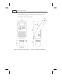
MonoScan User's Manual ii MonoScan User’s Manual Important Notice This manual is delivered subject to the following conditions and restrictions: ) This manual contains proprietary information belonging to Solid Applied Technologies Ltd. Such information is supplied solely for the purpose of assisting explicitly and properly authorized users of MonoScan. ) No part of its contents may be used for any other purpose, disclosed to any person or firm or reproduced by any means, electronic or mechanical, without the express prior written permission of Solid Technologies Ltd. ) The text and graphics are for the purpose of illustration and reference only. The specifications on which they are based are subject to change without notice. ) Information in this document is subject to change without notice. Corporate and individual names and data used in examples herein are fictitious unless otherwise noted. Copyright 2005. All rights reserved. MonoScan® is a registered mark of Solid Applied Technologies Ltd. Other company and brand products and service names are trademarks or registered trademarks of their respective holders. Date Revision Software Version Catalog Number Dec. 2004 1.2 4.090 English 680001E Safety Guidelines iii Safety Guidelines ) MonoScan must be installed, connected and operated according to the instructions in this Manual. ) Installation in hazardous area should be according to this manual and relevant control drawings. For more information consult with your distributor. ) If installed incorrectly or used for applications for which it is not intended, application-related dangers may arise. ) Only qualified personnel are authorized to install and operate MonoScan. ) Do not open the MonoScan unit. If the unit is opened, the warranty is null and void. ) Modifications and repairs to MonoScan are permissible only when the manufacturer expressly approves them. iv MonoScan User’s Manual Table of Contents Chapter 1..................................................................................... 1 Introducing MonoScan.................................................................................. 1 MonoScan Specifications .............................................................................. 3 Measuring Ranges................................................................................. 3 Mechanical Specifications............................................................................. 4 Electrical Specifications ........................................................................ 4 Sensor Recommendations..................................................................... 5 Chapter 2..................................................................................... 6 Installing MonoScan...................................................................................... 6 Precautions ................................................................................................... 6 Installing MonoScan...................................................................................... 7 Installing MonoScan on Threaded Flange/Thread-Free Flange .............. 8 Installing MonoScan via Extension Pipes ............................................ 10 Non-Intrinsically Safe Connections............................................................. 13 Chapter 3................................................................................... 20 Setting Up and Calibrating MonoScan ........................................................ 20 Using MonoScan Functions......................................................................... 22 Resetting MonoScan.................................................................................... 25 Entering the Tank Height Value .................................................................. 26 Defining Interfering Signals......................................................................... 28 Configuring 4mA Current Output ............................................................... 31 Configuring 20mA Current Output ............................................................. 35 Table of Contents v Selecting Low/High Dynamic Speed .......................................................... 37 Defining Working Area ............................................................................... 39 Selecting Distance or Level Display ............................................................ 41 Entering factor for Gas Compensation ........................................................ 43 Restoring the Default Settings ..................................................................... 45 Shifting the Blocking Distance..................................................................... 46 Verifying the Version Number..................................................................... 47 Defining 22mA Signal Error Messages......................................................... 48 Chapter 4 ...................................................................................50 MonoScan Open Channels .........................................................50 Selecting the Flow Measurement Settings ................................................... 50 Open Channels Flow Measurements ........................................................... 52 Flume/Weir Types .............................................................................. 53 Flumes/Weirs - European Standard .................................................... 54 Rectangular Suppressed Sharp-Crested Weir (Type 1) ....................... 54 Rectangular Contracted Sharp-Crested Weir (Type 2) ....................... 55 Trapezoidal (Cipolletti) Sharp-Crested Weir (Type 3) ........................ 56 V-Notch (Triangular) Sharp-Crested Weir (Type 4)............................ 57 Khafagi-Venturi Flume (Type 5).......................................................... 58 Parshall Flume (Type 6) ...................................................................... 59 Palmer Bowlus Flume Trapezoidal Throat Cross-Selection (Type 7) . 60 H Flume (Type 8)................................................................................ 61 Neyrpic Venturi Flume/Long-Base Weir (Type 9)............................... 62 Flumes/Weirs — American Standard.................................................. 64 Rectangular Suppressed Sharp-Crested Weir (Type 1) ....................... 64 vi MonoScan User’s Manual Rectangular Contracted Sharp-Crested Weir (Type 2) ...................... 65 Trapezoidal (Cipolletti) Sharp-Crested Weir (Type 3) ........................ 66 V-Notch (Triangular) Sharp-Crested Weir (Type 4)............................ 67 Parshall Flume (Type 5)...................................................................... 68 Palmer Bowlus Flume Trapezoidal Throat Cross-Selection (Type 6) .. 69 H Flume (Type 7)................................................................................ 70 Leopold-Lagco Flume (Type 8) ........................................................... 71 Chapter 5................................................................................... 72 Troubleshooting MonoScan ........................................................................ 72 22mA Signal Error Messages ....................................................................... 74 Appendix A — Gas Factor Table................................................ 75 Index ......................................................................................... 78 Table of Figures vii Table of Figures Figure 1: Front View of MonoScan ..............................................................................2 Figure 2: Side View of MonoScan................................................................................2 Figure 3: Threaded Flange/Thread-Free Flange Mounting ...........................................8 Figure 4: MonoScan Connector Front View ...............................................................11 Figure 5: MonoScan Conduit Adapter ........................................................................12 Figure 6: Non-Intrinsically Safe Positive Ground Connection ...................................13 Figure 7: Non-Intrinsically Safe Negative Ground Connection..................................13 Figure 8: Intrinsically Safe Positive Ground Connection............................................17 Figure 9: Intrinsically Safe Negative Ground Connection ..........................................18 Figure 10: MonoScan Functions Menus .....................................................................21 Figure 11: MonoScan Display and Function Buttons .................................................22 Figure 12: Scan Distance Process ...............................................................................28 Figure 13: Defining Working Area .............................................................................39 Figure 14: Rectangular Suppressed Sharp-Crested Weir ............................................54 Figure 15: Rectangular Contracted Sharp-Crested Weir.............................................55 Figure 16: Trapezoidal (Cipolletti) Sharp-Crested Weir.............................................56 Figure 17: V-Notch (Triangular) Sharp-Crested Weir ................................................57 Figure 18: Khafagi-Venturi Flume..............................................................................58 Figure 19: Parshall Flume ...........................................................................................59 Figure 20: Palmer Bowlus Flume Trapezoidal Throat Cross-Selection......................60 Figure 21: H Flume .....................................................................................................61 Figure 22: Leopold Lagco Flume................................................................................71 viii MonoScan User’s Manual Introducing MonoScan 1 Chapter 1 Introducing MonoScan MonoScan is an ultrasonic, continuous-level measurement gauge of mono-block construction (combining the sensor and electronic components in a single unit). MonoScan measures the height of both liquids and solids accurately. It can be used for the following measurement tasks: ) Liquid tanks with calm surfaces ) Solids tanks that are dust-free ) Open channel flow measurement MonoScan has a range of up to 15 m (49.21 ft) with an accuracy of 0.25% within that range. MonoScan is available in three models: ) MonoScan L for liquids (Standard Range/Short Range) ) MonoScan S for solids (Standard Range/Short Range) ) MonoScan O for open channels (Standard Range/Short Range) 2 MonoScan User’s Manual The following diagrams show the front and side views of MonoScan, and its dimensions: Figure 1: Front View of MonoScan Figure 2: Side View of MonoScan Introducing MonoScan 3 MonoScan Specifications Accuracy 0.25% of measuring range Resolution 1 mm (0.04") Beam angle 5° @ 3db point Ambient temperature compensation Automatic Measuring Ranges MonoScan L for liquids MonoScan S for solids MonoScan O for open channels Short Range 0.25 m — 5 m 0.82 ft — 16.4 ft Standard 0.6 m — 15 m 1.96 ft — 49.2 ft Short Range 0.25 m — 5 m 0.82 ft — 16.4 ft Standard 0.6 m — 8.5 m 1.96 ft — 27.8 ft Short Range 0.25 m — 5 m 0.82 ft — 16.4 ft Standard 0.6 m — 15 m 1.96 ft — 49.2 ft 4 MonoScan User’s Manual Mechanical Specifications Enclosure IP 65, Mono-block construction. Plastic enclosure: ABS+UV Pollution degree 2 (as per IEC61010) Insulation category II (as per IEC61010) Wetted parts Sensor body: PolyProp. PVDF, Coated aluminum (ECTFE) for Solid/Liquid model. Operating temperature -40° C to + 70° C (-40° F to +158° F) Mounting 2" BSP or 2" NPT Operating pressure 0.9 bar Dimensions 289 x 107 x 85 mm (11.38 x 4.21 x 3.35") Weight Up to 1.4 kg (3.08 lb) Electrical Specifications Display Integral LCD, four digits. Loop current 4 — 20 mA, 750 Ω @ 28 VDC Supply 12 — 28 VDC (CE certified) Certificates CE — EMC,FM-Safety, FCC. ATEX: EEX ia IIC T4 FM: Class I/Div. 1/ Groups A, B, C, D T4. CSA: (IS) Class I,II,III/ Div. 1/ Groups ABCDEFG/T4 NI: Class I,II,III/Div. 2/ Groups ABCD/T4 (no barriers required) Introducing MonoScan 5 Sensor Recommendations Material Description Coated Aluminum (HalarECTFE) Designed for complex environments with problematic echoes, such as non-conductive vapors, solids or liquids. Good performance in problematic applications. Usable in highly acidic or alcoholic environments. High sensitivity to echoes. 6 MonoScan User’s Manual Chapter 2 Installing MonoScan Precautions ) Ensure that MonoScan is mounted in an area that meets the stated temperature, pressure and technical specifications. ) Ensure that high-voltage sources or cables are at least 1 m away from the sensor and its cable. ) Use round cables with minimum diameter of 6 - 7 mm to ensure that the unit remains sealed, IP 65. ) Ensure that cables are routed correctly and tightened along walls or pipes. ) Installation and operation of this product should be performed, according to the Product User Manual and Product Certification. Otherwise the use of this product is prohibited. Installing MonoScan Installing MonoScan When installing MonoScan, ensure that it is: ) Mounted above the dead-zone area. NOTE: If the device enters the blocking distance (dead zone), it will not measure correctly. ) Positioned at least 0.5 m (1.64 ft) away from the tank walls. ) Perpendicular to the surface of the target. NOTE: Even the slightest difference in angle may affect echo quality. 7 8 MonoScan User’s Manual ) Placed as far as possible from noisy areas, such as a filling inlet. NOTE: When installed in a humid environment it is recommended to position the sensor on a tripod on top of the vessel. Installing MonoScan on Threaded Flange/Thread-Free Flange MonoScan is available in two thread types, 2" BSP or 2" NPT. MonoScan can be installed with threaded-flange mounting or with thread-free flange mounting, as shown below: Figure 3: Threaded Flange/Thread-Free Flange Mounting Installing MonoScan 9 NOTES: When installing a thread-free flange mounted unit, you will need a 2" locking nut to secure the unit inside the tank. When installing a threaded flange, ensure that it matches the MonoScan threads. ¾ To install MonoScan: 1 Insert the threaded end of MonoScan into the aperture at the top of the tank or pipe. 2 Bolt MonoScan into place in one of the following ways: ) Threaded-flange mounting: Screw the unit into a flange with a threaded 2" hole. ) Thread-free mounting: Place MonoScan in the flange, and bolt it from within the tank with a 2" locking nut. NOTE: Tighten the nut by hand only. When tightening the nut, hold the lower part of the MonoScan unit. Make sure that the seal is leak proof. 10 MonoScan User’s Manual Installing MonoScan via Extension Pipes If the level of the measured surface falls within the dead-zone area, you should use an extension pipe to mount MonoScan. When using an extension pipe, ensure that: ) The sensor is positioned in the center of the pipe. ) The pipe extension is parallel to the side/tank walls. ) The internal pipe diameter is at least 3" wide. When installing the MonoScan with extension pipes, follow these specifications: Pipe Length Internal Pipe Diameter 0.50 m (1.64 ft) 3" NOTE: It is always recommended to use interference signal feature (Pr.03) to locate interfering signals when using an extension pipe. Installing MonoScan 11 Connecting the MonoScan to a Power Cable Using a connector 1 Remove the retaining screw from the electrical connector. 2 Remove the male part from the MonoScan unit. 3 Separate the plastic electrical connector shell from the wiring block. 4 Connect the +24V wire to Terminal 1, connect the -24V wire to Terminal 2 on the Wiring Block. 5 Snap the electrical connector wiring block back into the electrical connector shell. 6 Pull the electrical connector to the MonoScan socket plug and fasten with the retaining screw provided. Figure 4: MonoScan Connector Front View NOTE: The cable for the mating connector must be at least 6 mm in diameter. 12 MonoScan User’s Manual Using a conduit 1 Remove the four retaining screws from the conduit adapter cover. 2 Pull the electrical wires through the 1/2" NPT/ M20 conduit connection. 3 Connect the -24V wire to Terminal 1, connect the +24V wire to Terminal 2 on the Wiring Block. 4 Return the adapter’s cover to its place properly. Make sure that the O-ring is placed correctly. Fasten the four retaining screws. Figure 5: MonoScan Conduit Adapter NOTE: The conduit adapter should not exceed a torque of 50 lb/In. To maintain the MonoScan properly sealed, make sure that conduit is firmly screwed to the conduit's adaptor. Installing MonoScan Non-Intrinsically Safe Connections Figure 6: Non-Intrinsically Safe Positive Ground Connection Figure 7: Non-Intrinsically Safe Negative Ground Connection 13 14 MonoScan User’s Manual Power Supply and Load Resistance Recommendations The following table specifies the recommended resistance range for each power supply voltage (Non-Intrinsically Safe). Power Supply Voltage Minimum Current on Resistor Maximum Current on Resistor 12 V 0Ω 50 Ω 15 V 0Ω 220 Ω 24 V 41 Ω 610 Ω 28 V 68 Ω 820 Ω Ripple/Noise Parameters Recommended for the Power Supply The following ripple/noise parameters are recommended for the power supply: ) For less than 15 V: 75 mV p-p max ) For more than 15 V: 100 mV p-p max Installing MonoScan 15 Intrinsically Safe Connections Hazardous Area Installation (For Ex version) Installation of the equipment shall be in accordance with the NEC Articles 504 and 505 and ISA RP 12.06.01 Recommended Practice for the Installation of Intrinsically Safe Circuits. Instructions specific to hazardous area installation. (Reference European ATEX Directive 94/9/EC, Annex II, 1.0.6.) The following instructions apply to equipment covered by certificate number Sira 03ATEX2134X: Remark: The certificate number has an ’X’ suffix, to indicate a special certification condition which does not apply to the MonoScan. ) The equipment may be used in a hazardous area with flammable gases and vapors with Apparatus Groups IIC, IIB and IIA and with temperature classes T1, T2, T3 and T4. ) The equipment is certified for use in ambient temperatures in the range of -40°C to +70°C and should not be used outside this range. ) Installation shall be carried out in accordance with the applicable code of practice by suitably trained personnel. ) The equipment is not intended to be repaired by the user. Repair of this equipment shall be carried out in accordance with the applicable code of practice. 16 MonoScan User’s Manual ) If the equipment is likely to come into contact with aggressive substances, then it is the responsibility of the user to take suitable precautions that prevent it from being adversely affected, thus ensuring that the type of protection is not compromised. Aggressive Substances - e.g. acidic liquids or gases that may attack metals or solvents that may affect polymeric materials. Suitable Precautions- e.g. regular checks as part of routine inspections or establishing from the material’s data sheet that it is resistant to specific chemicals. ) Certification marking as detailed in LB0010C. Installing MonoScan 17 Device parameters: Vi = 28 V Ii = 93mA Pi = 1.71 W Ci = 0 Pf Li = 0uH ATEX: EX ia IIC T4 FM: Class 1 Division I Group A, B, C, D T4. CSA: Intrinsically safe Class I,II,III/Division 1/ Groups ABCDEFG/T4 Barriers should be FM approved. Ta = +70°C; Type 4 The voltage to the barriers should not exceed 250V. Figure 8: Intrinsically Safe Positive Ground Connection Producer Zener Barrier Part Number MTL 7728- STAHL 9001/00-280100-10 Intrinsic Safety Approval Interconnection Barrier Terminal MonoScan Terminal CENELAC, CSA, ATEX, FM, UL 3 4 2 1 CENELAC, CSA, ATEX, FM, UL 3 4 2 1 NOTES: MonoScan (IS) is approved for hazardous area installation with the above specified barriers. Consult factory for a detailed information regarding usage of alternative barriers. 18 MonoScan User’s Manual Device parameters: Vi = 28 V Ii = 93mA Pi = 1.71 W Ci = 0 pF Li = 0uH ATEX: EX ia IIC T4 FM: Class 1 Division I Group A, B, C, D T4. CSA: Intrinsically safe Class I,II,III/Division 1/ Groups ABCDEFG/T4 Barriers should be FM approved. Ta = +70°C; Type 4 The voltage to the barriers should not exceed 250V. Figure 9: Intrinsically Safe Negative Ground Connection Producer Zener Barrier Part Number MTL 7787+ STAHL 9002/13-280110-00 9001/01-280100-10 Intrinsic Safety Approval Interconnection Barrier Terminal MonoScan Terminal CENELAC, CSA, ATEX, FM, UL 3 4 1 2 CENELAC, CSA, ATEX, FM, UL 3 4 1 2 NOTE: MonoScan (IS) is approved for hazardous area installation with the above specified barriers. Consult factory for a detailed information regarding usage of alternative barriers. Installing MonoScan 19 Power Supply and Load Resistance Recommendations The following table specifies the recommended power supply for MonoScan (Intrinsically Safe). Power Supply Voltage Minimum Resistor Value Maximum Resistor Value 18 V 41 Ω 220 Ω 24 V 41 Ω 310 Ω 28 V 68 Ω 520 Ω Installation in Class I, Division 2 Sites For any question before installation please consult with your distributor. For a detailed connection diagram refer to Non-Intrinsically Safe Connections drawings. NOTE: Warning! Explosion Hazard – Do not disconnect while circuit is live, unless the area is known to be Non-Hazardous. 20 MonoScan User’s Manual Chapter 3 Setting Up and Calibrating MonoScan This chapter explains how to set up and calibrate MonoScan for accurate measurement monitoring. MonoScan is supplied with preprogrammed default settings, making it ready for immediate operation. There is no need to change the default settings, unless you wish to calibrate MonoScan for your specific requirements; however, it is recommended that you replace the default tank height value with the actual tank height, as described on page 26. When using MonoScan, the tank height is calculated as the distance from the surface of the sensor to the bottom of the tank. You should enter this value whenever tank height is required. (For flow measurement, enter the precise flume height.) MonoScan contains eleven programs, referred to as functions, which enable you to change the default settings and calibrate MonoScan as required. These functions are accessed from a functions menu. The functions Pr01, Pr02, Pr04 and Pr05 are the most important to ensure correct usage of your MonoScan device (with the addition of Pr00 if using a MonoScan O model). Function Pr03 may be used if there are interfering signals. Setting Up and Calibrating MonoScan 21 The remaining functions (Pr06, Pr07, Pr08, Pr09 and Pr10) enable you to customize MonoScan for your monitoring requirements or to restore factory default settings. NOTE: Some functions are only relevant for particular MonoScan models. The diagram below shows the functions available in the functions menus for the MonoScan O, L and S models. Figure 10: MonoScan Functions Menus 22 MonoScan User’s Manual Setting flow measurement parameters (function Pr00) for the MonoScan Open Channels model is described in Chapter 4, MonoScan Open Channels. Setting parameters for all other functions and accessing the functions are described in this chapter. Using MonoScan Functions The LCD display screen, functioning in "normal" mode, provides continuously updated measurement readings. The display screen is also used to view MonoScan’s menu options, function settings and data values, accessed by using MonoScan’s function buttons. The picture below shows the upper part of MonoScan: LCD display Next button Enter button Back button Escape button Figure 11: MonoScan Display and Function Buttons Setting Up and Calibrating MonoScan The function buttons are used to perform various operations, summarized in the following table. Button Uses Include: ) Accessing the functions menu (when pressed simultaneously with ) ) Selecting functions ) Progressing to the next step of a function ) Moving from left to right between displayed digits (see note on the following page) ) Saving changes to data ) Accessing the functions menu (when pressed simultaneously with ) ) Exiting the functions menu to restore the distance reading ) Moving from right to left between displayed digits (see note on following page) ) Exiting a function without saving changes ) Clearing error messages ) Scrolling through the functions menu or ) Scrolling through available data values in functions ) NEXT button only: Recording interfering signals (see page 28) 23 24 MonoScan User’s Manual NOTE: Within some functions, the digits in the displayed value can be individually modified. This is indicated by a flashing digit (flashing digits are shown in gray in the display illustrations, for example, ). In this case, the ENT and ESC buttons enable you to move between the digits. Each flashing digit can be modified using the BACK and NEXT buttons. ¾ To start up MonoScan and access the functions: Press/Action > Connect MonoScan to power supply > After a brief pause > and (simultaneously) > or > Display Explanation Temporary display while MonoScan takes a reading. For example: Distance reading. For example: Enters the functions menu. Used to search for the required menu selection. Accesses the selected function. Setting Up and Calibrating MonoScan 25 NOTES: If an error message the main menu. appears, press the ESC button to return to Values are displayed in meters and centimeters or feet and inches, according to the version of MonoScan. Resetting MonoScan The PR01 function enables you to do a reset, refreshing the MonoScan measurement reading. (Other saved function settings are not changed.) After resetting, the actual reading is displayed on the LCD, and MonoScan begins to scan (same as in turning the unit on/off). The reset function may sometimes be required after changing one of the MonoScan’s settings or after receiving an error message. NOTE: During reset the MonoScan will display 8.8.8.8 followed by 22mA current output. 26 MonoScan User’s Manual ¾ To reset MonoScan: Press/Action > Display Required menu selection. and (simultaneously) > > > Explanation Temporary display while MonoScan takes reading. After a brief pause and (simultaneously) For example, Distance reading. Returns to the functions menu. Entering the Tank Height Value The Pr02 function enables you to enter the tank height. The default value is the highest value in the relevant measurement range for your model. If you enter a value that exceeds this highest value, the Err error message is displayed and the value is not saved. NOTES: Whenever the tank height is required, you should enter the distance from the surface of the sensors to the bottom of the tank. For flow measurement, enter the precise distance from the sensor to the bottom of the flume (the deepest point between the flume and sensor). The first digit can be modified to read between 0 and 1 for metric units or between 0 and 5 for feet units. For Shift Blocking Distance refer to Chapter 3, page 46 . Setting Up and Calibrating MonoScan ¾ 27 To enter the tank height value: Press/Action Display Explanation > Required menu selection. > Indicates the measurement unit, either meters or feet (according to the MonoScan version). > For example > or Displays last saved tank height or default value (maximum value in range). Used to enter a new value, as described on page 26. or > To save the new value, OR > when standing press on the far-right digit. After YES is displayed, the display returns to the functions menu. To return to the main menu without saving, press when standing on the far-left digit. 28 MonoScan User’s Manual Defining Interfering Signals The Pr03 function enables you to locate and store up to six interfering signals (false echoes) in the MonoScan memory, to avoid having obstructions such as a tank agitator or sidewall interfere with the measurement of the contents. Defining interfering signals is done while the tank is empty. Echo amplitude Memory stored interferences (up to 4) Real echo Distance Figure 12: Scan Distance Process Each reading (scan distance) taken using the Pr03 function is stored as an interfering signal, until a reading is achieved that indicates the real echo. If six interfering signals are already stored, the following values will not be saved. NOTES: The reading of the actual target height may not be exact, for example, a target height of 6 m may give a reading in the range 5.98 - 6.02. The displayed values are in distance units. Setting Up and Calibrating MonoScan ¾ To define interfering signals: Press/Action Display > Select Search to locate acoustic interferences, or Clear to delete stored interferences. or > Displayed after the selection for 3 seconds and then the menu returns to Pr.03. > > Explanation Required menu selection. > > 29 Temporary display while MonoScan searches for interfering signals. After a brief pause For example, Depth to interfering signal. Saves the interfering signal, then searches again and displays the next reading. Continue to press this button to save up to six interference readings. 30 MonoScan User’s Manual Press/Action > > Display Explanation For example, Actual target height reading indicates that there are no more interfering signals. Saves the entered values. NOTES: If the value represents an interference or false echo or false target press NEXT. If the value represents the real target, real distance – press ENT. Setting Up and Calibrating MonoScan 31 Configuring 4mA Current Output Pr04 function enables you to enter values to be used as the 4mA mark for remote monitoring. You can define the 4mA values for Level, Distance or Flow measurements. The measurement values types should be defined in Pr.04 (described on page 31). These definitions will be applicable as well for the 20mA values defined in Pr.05. Distance and level measurements can be defined for both Solid and Liquid MonoScan models. For MonoScan Flow models, distance, level and flow measurements can be defined. To set 4mA and 20mA for level measurements you should configure Pr04 and Pr05 for level values. For example, if we measure a tank with tank height configured for 5 meters, the 4mA values will represent zero tank level and 20mA values will represent full tank level. Therefore, the value entered in Pr04 will be 0.000m and the value entered in Pr05 will be 5.000m. When setting 4mA and 20mA for distance measurements, 4mA values will represent the minimal distance between the surface of the target and the sensor and 20mA values will represent the maximal distance between the sensor and the surface of the target. Therefore, 4mA represents the full part of the tank and 20mA represents the empty part of the tank. 32 MonoScan User’s Manual ¾ To enter 4mA values: Press/Action Display > Explanation Required menu selection. > For example, Select 4mA (and 20mA) values format: Level (L000), Distance (d000) and Flow (F000). For example Last saved 4mA level or zero default value. or > > > or or Used to enter a new value, as described on page 26. Setting Up and Calibrating MonoScan Press/Action > Display 33 Explanation To save the new value, press when standing on the far-right digit. After YES is displayed, the display returns to the functions menu. > To return to the main menu without saving, press when standing on the far-left digit. 34 MonoScan User’s Manual NOTES: The values for 4mA and 20mA must be different; otherwise an Err error message is displayed. The values for 4mA and 20mA should not be greater than the value used for the tank height (Pr02). Because of the dead-zone, the distance between the sensor and the surface of the target at its highest level should be a minimum of 0.25 m/0.8 ft for Short-Range models, or 0.6 m/1.96 ft for StandardRange models. The first digit of the 4mA value can be modified to read between 0 and 1 for metric units or between 0 and 5 for U.S. Standard units. After accessing the Pr04 function, the unit generates a fixed current of 22mA on the 4-20mA line. When the MonoScan reverts to regular scanning mode, the 4-20mA line returns to regular functioning. The default values for 4mA and 20mA in Solid and Liquid MonoScan models are level. The default values for 4mA and 20mA in Flow MonoScan models are flow. When changing from one measurement mode to another, the measurement units will be changed automatically (for example, when changing from level mode to flow mode, the units will change from meters to M^3/H.) The measurement mode selected for the 4-20mA values will not influence the measurement mode selected for the display (Pr.08). In case of power rest, measurement configuration (level, distance, flow) will be saved according to the unit's last configuration. Setting Up and Calibrating MonoScan 35 Configuring 20mA Current Output The Pr05 function enables you to enter values to be used as the 20mA mark for remote monitoring. ¾ To enter 20mA values: Press/Action Display > Explanation Required menu selection. > > For example > or Last saved 20mA level or default value (maximum value in range). Used to enter a new value, as described on page 26. or > To save the new value, OR when standing press on the far-right digit. After YES is displayed, the display returns to the functions menu. 36 MonoScan User’s Manual Press/Action > Display Explanation To return to the main menu without saving, press when standing on the far-left digit. NOTES: Type of measurement (level, distance, flow) selected in Pr.04 is also applicable for Pr.05. The values for 4mA and 20mA must be different; otherwise an Err error message is displayed. The values for 4mA and 20mA should not be higher than the value used for the tank height (Pr02). The first digit of the 20mA value can be modified to read between 0 and 1 for metric units or between 0 and 5 for U.S. Standard units. After accessing the Pr05 function, the unit generates a fixed current of 22mA on the 4-20mA line. When the MonoScan reverts to regular scanning mode, the 4-20mA line returns to regular functioning. Please refer to chapter 5 Troubleshooting for 20mA error indications. Setting Up and Calibrating MonoScan 37 Selecting Low/High Dynamic Speed (Open Channels and Liquid Only) The Pr06 function enables you to choose the required speed level. There are two settings available: ) SE 0: Low dynamic mode (default setting). This mode provides slower readings with a greater degree of accuracy (Rate of up to 80 cm/31in per min’). ) Fail Safe: 10 minutes. ) SE 1: High dynamic mode. This mode provides faster readings but with less precision (Rate of up to 100 cm/39 in per min’). ) Fail Safe: 3 minutes. NOTE: Fail – Safe timer determines the waiting period from an echo loss till a transmission of an error signal. 38 MonoScan User’s Manual ¾ To select the speed mode: Press/Action Display Explanation > Required menu selection. > Displays the current operation mode setting. or > Used to toggle between the operation modes. or > Saves the selected operation mode. Setting Up and Calibrating MonoScan 39 Defining Working Area The Pr07 function allows you to add distance range that exceeds the tank’s height, thus enabling accurate readings of complicated tank shapes with conic ending. This may be required when the vessel has a conical bottom shape which is causing false echoes and consequently faulty measurements. The minimal value can be the entered tank height and the maximal value can be double the value of the entered tank height (limited to 15m/49ft). The default setting is the entered tank height. Figure 13: Defining Working Area NOTE: It is recommended to use the Pr.07 function only in Distance mode. 40 MonoScan User’s Manual ¾ To define a Working Area: Press/Action Display Explanation > Required menu selection. > Displayed when entering the function. > > for example: or Displays the value last saved in the tank height (default). The entered value should not be more than double the tank height and should not exceed the MonoScan’s maximum measuring range (15m/49ft). Used to enter a new value, as described on page 26. or > Saves the entered value. > Used to move on to the next function. or Setting Up and Calibrating MonoScan 41 Selecting Distance or Level Display The Pr08 function enables you to choose whether MonoScan displays either distance or level measurements. There are two settings available: ) d000: Distance mode (default setting): In this mode, MonoScan displays the distance from the sensor to the surface of the contents. ) L000: Level mode: In this mode, MonoScan displays the level of the contents from the bottom of the tank. NOTE: The measurement mode selected for the display will not influence the measurement mode selected for the 4-20mA values (Pr.04). 42 MonoScan User’s Manual ¾ To select distance or level display: Press/Action Display Explanation > Required menu selection. > Displays the current distance/level mode setting. or > Used to toggle between the modes. or > Saves the selected mode. Setting Up and Calibrating MonoScan 43 Entering factor for Gas Compensation Function Pr.09 enables you to compensate for sound velocity changes in different types of gasses. You can enter the appropriate factor for each type of gas listed on the ‘Gas Factor Table’ (Appendix A). For example the sound velocity in air (in room temperature) is 343 m/sec and for Methane (Ch4) 445.82 m/sec, therefore a factor of 445.82/343 = 1.29 should be entered to compensate for this type of gas. This factor will compensate in cases when the gas compound consists on 100% Methane. In case the gas is not pure, the sound velocity cannot be estimated and therefore a minor deviation could appear. It is recommended to use a reference measurement indicator (using a tape or other measuring device) and compare the measurement results between the MonoScan and the reference measurement indicator. If the result is correct, press ENT. If the accuracy deviation is higher than expected, continue and calibrate the factor to meet the gas maintained in the vessel. For example, if the gas composition consists of water and gas you can add +/- 0.01 to the factor figure already entered, to meet your application requirements. The ’Gas Factor Table’ (page 75) supports up to 33 different types of gasses. For any other type of gas, not included in this table, please refer to Solid AT Customer Support. ([email protected]) 44 MonoScan User’s Manual ¾ To enter a gas compensation factor: Press/Action Display Explanation > Required menu selection. > Default screen. > Default value. > Choose a factor from the ’Gas Factor Table’ (Appendix A, Page 75). or or For example: > This is the factor for Ethanol. Saves the chosen gas factor. NOTES: Repeat this procedure if the measurement results differ from the actual material level measured with a reference tape (or other reference measurement method). Add or reduce 0.01 to calibrate the factor figure already entered. Updated on-screen results may take a few seconds to appear. Setting Up and Calibrating MonoScan 45 Restoring the Default Settings The Pr10 function allows clearing all user-defined settings and reverting to the default factory settings. Default factory settings are: Pr.00: GPM 1U01 or M3/Hr 1E01 Pr.02: Sbd 00.00, E000, Tank Height =default Pr.03: Resets all interfering signals Pr.04: Solid/Liquid device L000, 00.00 or Flow device F000, 00.00 Pr.05: Solid/Liquid device Tank Height = Pr.02 Pr.06: Pr.07: Pr.08: Pr.09: Flow device 55500 M³/Hr or 244400 GPM SE 0 (Liquid & Flow) Tank Height = Pr.02 d000 01.00 NOTE: If you decide not to revert to the default settings, press ESC when CLCL is displayed. A redo option is not available when ENT has been pressed. ¾ To restore the default settings: Press/Action > Display Explanation Required menu selection. > > Reverts all settings to default factory settings. 46 MonoScan User’s Manual Shifting the Blocking Distance This function enables you to define an area in which measurement results would be ignored. This option is applicable for installations requiring extension pipes or nuzzles positioned above the material level. This area should fit the pipe/nuzzle length to eliminate false echoes and to provide accurate and stable measurement readings. ¾ To shift the blocking distance: Follow the directions given for Entering the Tank Height Value, page 26. Instead of entering the tank height value, enter 00.01, and continue as follows: Press/Action Display Explanation > Insert this code to enter the Blocking Distance area. > This message will flash for a few seconds, indicating an entry to the Blocking Distance area. > For example, or Shifts the blocking distance to 0.75m (2.46 ft). or > Saves this entry and returns to Pr.02. Setting Up and Calibrating MonoScan 47 NOTES: Shifting of the Blocking Distance is limited to 1.5m/4.9ft. The value entered to the Sbd incorporates the Dead Zone Value. Pr.10 (Clear) reverts the blocking distance to its default. Echo received from the defined Blocking Distance area will be ignored by the MonoScan and the measurement result will be based on the next echo. When installing via extension pipe add approx. 15 cm (5.9 in) to the SBD length (i.e. the extension pipe length). Make sure that this addition would not overlap with the maximal height of substance being measured. Verifying the Version Number In addition to the functions described, you can verify the MonoScan version number. ¾ To verify the MonoScan version number: Follow the directions given for Entering the Tank Height Value, page 26. Instead of entering the tank height value, enter 00.17, and continue as follows: Press/Action Display Explanation > > > After a brief pause Displays the version number. 48 MonoScan User’s Manual Defining 22mA Signal Error Messages MonoScan allows you to define if the following signal error indications: Near Zone and Lost Echo, will be active when the current output reaches 22mA. The MonoScan default setting enables 22mA analog current and error messages to appear on its LCD display. Near Zone - whenever the distance is below the defined Dead Zone (depending on the MonoScan model you are message will be displayed on the LCD. using) Lost Echo - whenever the echo is lost, or in cases when the measurement results exceed the tank height or when a returned echo is not received displayed on the MonoScan’s LCD. message will be You can choose to enable or disable these error messages and 22mA analog signal as follows: ) d000: Disable ) E000: Enable (default setting) Refer to Chapter 5, Troubleshooting for a detailed list of the 22mA signal error messages. Setting Up and Calibrating MonoScan ¾ 49 To disable/enable 22mA signal error in the MonoScan: Follow the directions given for Entering the Tank Height Value, page 26. Instead of entering the tank height value, enter 00.16, and continue as follows: Press/Action Display Explanation > Choose disable > Used to toggle between the modes. or Disables the 22mA error messages NOTE: When the error signals are disabled the following current outputs will be displayed: If the MonoScan is set to Level or Flow then F.F.F.F will indicate 20mA and E.E.E.E will indicate 4mA. If the MonoScan is set to Distance then F.F.F.F will indicate 4mA and E.E.E.E will indicate 20mA. 50 MonoScan User’s Manual Chapter 4 MonoScan Open Channels This section describes how to set flow measurement parameters for open channels, and explains the flume/weir codes methodology used when setting up flow measurements. Selecting the Flow Measurement Settings The Pr00 function enables you to select one of the preset flumes/weirs settings for flow measurements. This function is available only in MonoScan O models. When setting flow measurement parameters in the Pr00 function, the flume/weir type value (X) is entered first, followed by the letter (U) or (E) that represents either American (USA) or European standard flume/weir. The code value (YY) represents the appropriate flume/weir dimensions in the following format: . The open channel types and codes are described in Open Channels Flow Measurements, page 52. NOTES: Refer to Chapter 3, Setting Up and Calibrating MonoScan, for an explanation of accessing and using the MonoScan functions menu. All flow measurement values are displayed divided by 1000. MonoScan Open Channels ¾ 51 To select the flow measurement settings: Press/Action Display > Explanation Required menu selection. > For example: Indicates the measurement unit for flow, either GPM (in American standard) or M3 (in European standard) (according to the MonoScan version). > Displays last saved flow measurement setting or default value, with first digit flashing (U — American standard and E — European standard). > Use to select a new type value (X). or > Last two digits of the display flash. > Use to select a new flume/weir length code (YY). or > Selected values are saved. 52 MonoScan User’s Manual Open Channels Flow Measurements The flume/weir type code methodology used when setting up open channels is based on three digits: X(U/E)YY Where: X refers to the particular flume/weir type U/E refers to either American or European standard flumes/weirs YY refers to the specific flume/weir dimensions The types of flumes/weirs are available in European standard and American standard. Default setting is European standard. When working in European standard the default flow measurement units will be M³/Hr, and in American standard the default flow measurement units will be G.P.M . MonoScan Open Channels 53 Flume/Weir Types This is the first value (X) entered for the Pr00 function. The following flume/weir types are available both in European and American standard: Type (X) European Standard Pages 54 - 63 American Standard Pages 64 - 71 1 Rectangular Suppressed SharpCrested Weir, Page 54 Rectangular Suppressed SharpCrested Weir, Page 64 2 Rectangular Contracted SharpCrested Weir, Page 55 Rectangular Contracted SharpCrested Weir, Page 65 3 Trapezoidal (Cipolletti) SharpCrested Weir, Page 56 Trapezoidal (Cipolletti) SharpCrested Weir, Page 66 4 V-notch (Triangular) SharpCrested Weir, Page 57 V-notch (Triangular) SharpCrested Weir, Page 67 5 Khafagi-Venturi Flume, Page 58 Parshall Flume, Page 68 6 Parshall Flume, Page 59 Palmer Bowlus Flume Trapezoidal Throat CrossSelection, Page 69 7 Palmer Bowlus Flume Trapezoidal Throat CrossSelection, Page 60 H Flume, Page 70 8 H Flume, Page 61 Leopold-Lagco Flume, Page 71 9 Neyrpic Venturi Flume/LongBase Weir, Page 62, 63 54 MonoScan User’s Manual Flumes/Weirs - European Standard Rectangular Suppressed Sharp-Crested Weir (Type 1) Code (YY) Crest Length (cm) 01 20 02 40 03 60 04 80 05 100 06 150 07 200 08 300 Figure 14: Rectangular Suppressed Sharp-Crested Weir MonoScan Open Channels Rectangular Contracted Sharp-Crested Weir (Type 2) Code (YY) Crest Length (cm) 01 20 02 30 03 40 04 50 05 60 06 80 07 100 08 150 09 200 10 300 Figure 15: Rectangular Contracted Sharp-Crested Weir 55 56 MonoScan User’s Manual Trapezoidal (Cipolletti) Sharp-Crested Weir (Type 3) Code (YY) Crest Length (cm) 01 30 02 45 03 60 04 80 05 100 06 150 07 200 08 300 Figure 16: Trapezoidal (Cipolletti) Sharp-Crested Weir MonoScan Open Channels 57 V-Notch (Triangular) Sharp-Crested Weir (Type 4) Code (YY) V-Notch Angle (o) 01 90 02 60 03 53.8 04 45 05 30 06 28.4 07 22.5 British Standard 08 90 09 45 10 22.5 Figure 17: V-Notch (Triangular) Sharp-Crested Weir 58 MonoScan User’s Manual Khafagi-Venturi Flume (Type 5) Code (YY) Flume Type b0 (cm) 01 QV 302 12 02 QV 303 30 03 QV 304 40 04 QV 305 50 05 QV 306 60 06 QV 308 80 07 QV 310 100 08 QV 313 130 09 QV 316 160 Figure 18: Khafagi-Venturi Flume MonoScan Open Channels Parshall Flume (Type 6) Code (YY) Throat Width (in) Code (YY) Throat Width (in) 01 1 11 60 02 2 12 72 03 3 13 96 04 6 14 120 05 9 15 144 06 12 07 18 08 24 09 36 10 48 Figure 19: Parshall Flume 59 60 MonoScan User’s Manual Palmer Bowlus Flume Trapezoidal Throat Cross-Selection (Type 7) Code (YY) Conduit Diameter (in) D 01 6 02 8 03 10 04 12 05 15 06 18 07 21 08 24 09 27 10 30 Figure 20: Palmer Bowlus Flume Trapezoidal Throat Cross-Selection MonoScan Open Channels H Flume (Type 8) Code (YY) Flume Size (ft) Measurement Point (cm) 01 0.5 5 02 0.75 7 03 1 9 04 1.5 14 05 2 18 06 2.5 23 07 3 28 08 4.5 41 Figure 21: H Flume 61 62 MonoScan User’s Manual Neyrpic Venturi Flume/Long-Base Weir (Type 9) Neyrpic Venturi Flume Code (YY) Venturi Flume Type 01 1253AX 02 1253AY 03 1253AZ 04 1253A 05 1253B 06 1253C 07 1253D 08 1253E 09 1253F Figure 22: Neyrpic Venturi Flume MonoScan Open Channels Long-Base Weir Code (YY) Long-Base Weir Type 10 1245A 11 1245B 12 1245C 13 1245D Figure 23: Long-Base Weir 63 64 MonoScan User’s Manual Flumes/Weirs – American Standard Rectangular Suppressed Sharp-Crested Weir (Type 1) Code (YY) Crest Length (in) 01 12.00 02 18.00 03 24.00 04 30.00 05 36.00 06 48.00 07 60.00 08 72.00 09 96.00 Figure 12: Rectangular Suppressed Sharp-Crested Weir MonoScan Open Channels Rectangular Contracted Sharp-Crested Weir (Type 2) Code (YY) Crest Length (in) 01 12.00 02 18.00 03 24.00 04 30.00 05 36.00 06 48.00 07 60.00 08 72.00 09 96.00 Figure 13: Rectangular Contracted Sharp-Crested Weir 65 66 MonoScan User’s Manual Trapezoidal (Cipolletti) Sharp-Crested Weir (Type 3) Code (YY) Crest Length (in) 01 12.00 02 18.00 03 24.00 04 30.00 05 36.00 06 48.00 07 60.00 08 72.00 09 96.00 Figure 14: Trapezoidal (Cipolletti) Sharp-Crested Weir MonoScan Open Channels 67 V-Notch (Triangular) Sharp-Crested Weir (Type 4) Code (YY) V-Notch Angle (o) 01 90 02 60 03 45 04 30 05 22.5 Figure 15: V-Notch (Triangular) Sharp-Crested Weir 68 MonoScan User’s Manual Parshall Flume (Type 5) Code (YY) Throat Width (in) Code (YY) Throat Width (in) 01 1 12 60 02 2 13 72 03 3 14 96 04 6 15 120 05 9 16 144 06 12 07 18 08 24 09 30 10 36 11 48 Figure 16: Parshall Flume MonoScan Open Channels 69 Palmer Bowlus Flume Trapezoidal Throat Cross-Selection (Type 6) Code (YY) Conduit Diameter (in) D Code (YY) Conduit Diameter (in) D 01 4 11 30 02 6 12 36 03 8 13 42 04 10 14 48 05 12 15 60 06 15 16 72 07 18 08 21 09 24 10 27 Figure 17: Palmer Bowlus Flume Trapezoidal Throat Cross-Selection 70 MonoScan User’s Manual H Flume (Type 7) Code (YY) Flume Size (in) Measurement Point (in) 01 6 1.96 02 9 2.75 03 12 3.54 04 18 5.51 05 24 7.08 06 30 9.05 07 36 11.02 08 54 16.14 Figure 18: H Flume MonoScan Open Channels 71 Leopold-Lagco Flume (Type 8) Code (YY) Crest Length (in) Code (YY) Crest Length (in) 01 4 11 36 02 6 12 42 03 8 13 48 04 10 14 54 05 12 15 60 06 15 16 66 07 18 17 72 08 21 09 24 10 30 Figure 22: Leopold Lagco Flume 72 MonoScan User’s Manual Chapter 5 Troubleshooting MonoScan This chapter describes how to resolve problems that may occur when calibrating MonoScan, as follows: Error Description Solution Noise in area. Check that the power supply is appropriate. Faulty power supply. Make sure that the power supply corresponds with the specifications described in Chapter 2, Installing MonoScan. If the problem persists, replace the power supply. Sensor disconnected. Contact the distributor for further instructions. Any combination of three 8s and one 1: Indicates an electrical shortage caused by depressing the buttons for too long. Contact the manufacturer for further instructions. Troubleshooting MonoScan Error 73 Description Solution Appears for several seconds after restarting the unit. If it is displayed for more than several seconds, it may be due to one of the following: Make sure that the power supply corresponds with the specifications described in Chapter 2, Installing MonoScan. If the problem persists, replace the power supply. ) Power supply voltage is too low ) Load resistor resistance is too high or unnecessary ) A random pulse that causes the unit to automatically restart Measurement value is greater than 9999. Double check the unit configuration (Tank h, type of flume, 4-20mA settings.) In Flow mode, appears when Decrease the Tank Height the entered tank height is value. incorrect. 74 MonoScan User’s Manual 22mA Signal Error Messages The following list of messages will appear on the display and coincides with a 22mA analog current error output signal (when the error signals messages are enables): Error Description Solution Sensor disconnected. Contact the distributor for further instructions. Near dead zone. (depends on the measurement definitions) Move the sensor farther from the dead zone area. Tank empty. (depends on the measurement definitions) Check the level of material in the tank. Noise in area. (indicated by 22mA if the Error Signals are Enabled). Check that the power supply is appropriate. Faulty power supply. (indicated by 22mA if the Error Signals are Enabled). Make sure that the power supply corresponds with the specifications described in Chapter 2, Installing MonoScan. If the problem persists, replace the power supply. Gas Factor APPENDIX A 75 Appendix A Gas Factor The following table contains 33 different types of gasses and their factor for compensating the sound velocity: Gas Symbol Factor Acetic Acid C2h4o2 0.62 Acetone C3h6o 0.63 Acetaldehyde C2h4o 0.74 Acetyl Chloride C2h3c1o 0.54 Acetylene C2h2 0.99 Ammonia H3n 1.26 Argon Ar 0.92 Benzene C6H6 0.53 Bromine Br2 0.41 Bromochlorodifluoromrthane Cbrclf2 0.37 Butanone CH3COCH2CH3 0.56 76 MonoScan User’s Manual Gas Symbol Factor Carbon Dioxide CO2 0.77 Carbon Monoxide CO 1.01 Carbon Tetrachloride CCI4 0.38 Chlorine Cl2 0.68 Dimethyl Ether C2h6o 0.71 Ethane C2h6 0.90 Ethanol C2h6o 0.71 Ethylene C2h4 0.95 Helium He 2.93 Hydrogen H2 3.79 Hydrogen Sulfide H2S 0.89 Isopropyl Alcohol C3h8o 0.62 Methane CH4 1.29 Methyl Hydrazine Ch6n2 0.71 Neon Ne 1.30 Nitrogen N2 1.01 Gas Factor APPENDIX A Gas Symbol Factor Nitromethane CH3NO2 0.63 Oxygen O2 1.02 Propane C3H8 0.72 Propanol C3H8O 0.61 Tetrahydrofuran C4H8O 0.57 77 78 MonoScan User’s Manual Index 2 20 mA mark, 35 F False echoes, 28 4 Flow measurement settings, 50 Flume/weir types, 53 Flumes 4 mA mark, 31 B H, 61, 70 Khafagi-Venturi, 58 Neyrpic Venturi, 62 Buttons Palmer Bowlus Trapezoidal Throat function, 23 D Cross-Selection, 60, 69 Parshall, 59, 68 Function buttons, 23 Default settings Functions restoring, 45 Defining working area, 39 accessing, 24 Defining 22mA signal error messages, menu, 21 48 G Dimensions, 2 Distance measurement display, 41 Gas factor table, 75 Dynamic H low/high speed, 37 E H Flume, 61, 70 High dynamic setting, 37 Electrical specifications, 4 I Entering factor for gas compensation, 43 Installing MonoScan, 7 Index threaded-flange mounting, 8 specifications, 3 thread-free flange mounting, 8 N via extension pipes, 10 Interfering signals, 28 Intrinsically safe 79 Neyrpic Venturi Flume/Long-Base Weir, 62 ground connections, 15 power supply, 19 K Non-intrinsically safe ground connections, 13 power supply, 14 O Khafagi-Venturi Flume, 58 L Open channels flow measurements, 52 Level measurement display, 41 flume/weir code methodology, 52 Load resistance recommendations, 14, flume/weir types, 53 19 P Long-Base Weir, 63 Low dynamic setting, 37 M Measurement distance display, 41 level display, 41 Measuring Palmer Bowlus Flume Trapezoidal Throat Cross-Selection, 60, 69 Parshall Flume, 59, 68 Power supply recommendations, 14, 19 ripple/noise parameters, 14 Precautions, 6 ranges, 3 R Mechanical specifications, 4 MonoScan dimensions, 2 measuring ranges, 3 models, 1 resetting, 25 setting up, 20 Rectangular Contracted Sharp-Crested Weir, 55, 5 Supressed Sharp-Crested Weir, 54,64 Remote monitoring 80 MonoScan User’s Manual 20 mA, 35 4 mA, 31 V Resetting MonoScan, 25 Restoring default settings, 45 Ripple/noise parameters, 14 S Version number displaying, 47 V-Notch (Triangular) Sharp-Crested Weir, 57, 67 Sensors W recommended types, 5 Setting up, 20 Weirs Settings Long-Base, 63 restoring default, 45 Sharp-Crested Weir Rectangular Contracted, 55, 65 Rectangular Suppressed, 54, 64 Trapezoidal (Cipolletti), 56, 66 V-Notch (Triangular), 57,67 Signals Rectangular Contracted SharpCrested, 55,65 Rectangular Supressed SharpCrested, 54,64 Trapezoidal (Cipolletti) SharpCrested, 56,66 V-Notch (Triangular) Sharp-Crested, interfering, 28 57,67 Signal error messages, 48 Specifications, 3 electrical, 4 mechanical, 4 Speed mode, 37 T Table for gas compensaion factor, 75 Tank height value, 26 Trapezoidal (Cipolletti) Sharp-Crested Weir, 56, 66 Troubleshooting, 72 Working Area, 39