1
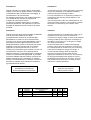
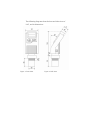
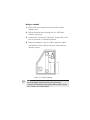
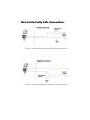
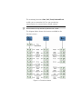
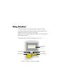
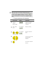
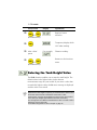
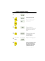
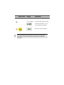
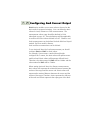
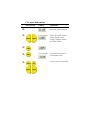
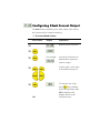
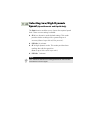
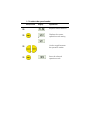
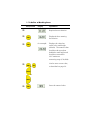
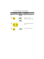
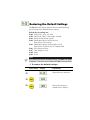
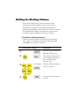
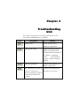
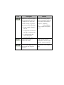
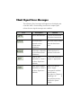
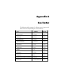
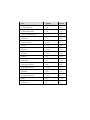
Manuale Operativo
Operating Manual
Serie ULG
Trasmettitori di livello ad ultrasuoni
ULG series
Ultrasonic level gauge
Introduzione
Introduction
Questo manuale non contiene tutte le informazioni
relative ad ogni tipo di apparecchiatura, né prende in
considerazione tutti i possibili casi di montaggio, di
funzionamento o di manutenzione.
Per maggiori informazioni o per problemi particolari
non considerati nel manuale Vi preghiamo di
rivolgerVi al nostro ufficio tecnico.
La garanzia é quella prevista nelle ns. condizioni
generali di assistenza. Tale garanzia non viene né
ampliata né limitata da quanto contenuto in questo
manuale.
This manual does not contain information concerning
all type of transmitters or all different installation
and/or working and mounting solutions.
For more information or for particular problems not
considered in this manual, please address to our
technical office.
The warranty period is the one contemplated in our
general servicing conditions. This warranty is neither
increased nor restricted by the contents of this
manual.
Attenzione!
Attention!
Questo strumento deve essere installato ed utilizzato
solo da personale qualificato che abbia
precedentemente verificato la correttezza della
alimentazione in modo che sia in funzionamento
normale, sia in caso di guasto dell'impianto o di sue
parti nessuna tensione pericolosa possa arrivare
all'apparecchiatura. Poiché lo strumento può essere
utilizzato sia con alte pressioni sia con sostanze
aggressive va tenuto presente che un uso non
corretto può portare danni gravi a persone e cose. Un
funzionamento corretto e sicuro presuppone un
adeguato trasporto, immagazzinamento e montaggio
nonché una manutenzione appropriata. E' pertanto
necessario affidare l'apparecchiatura a persone che
abbiano esperienza con il montaggio, la messa in
servizio ed il funzionamento e che siano in possesso
dei titoli per svolgere la loro attività con riferimento
agli "Standard di Sicurezza".
This instrument has to be installed and used only by
qualified persons who have first checked the
correctness of supply voltage so that both in standard
working conditions and in presence of damages of
the plant or of any part of it, no dangerous voltage
can reach the instrument.
As the instrument can be utilized both with high
pressure values and with aggressive media it must
be considered that an incorrect use of it could bring
even serious damages to people and things. A
correct and safe working needs an adequate
transport, stock and mounting other than an
appropriate maintenance service. So it is necessary
for the people handling these apparatus to have
knowledge and experience in mounting, servicing
and working and to have title to do their job with
reference to “Safety Standards“.
La Società si riserva il diritto
di modificare il contenuto di
questo manuale senza preavviso.
The Company could modify this
manual in any moment
without previous advice.
Rev
Data/Date
Descrizione/Description
Red
Chk
App
0
26/01/09
Emissione
MC
RS
EV
Chapter 1
Introducing ULG
ULG is an ultrasonic, continuous-level measurement
gauge of mono-block construction (combining the sensor and
electronic components in a single unit). ULG measures
the height of both liquids and solids accurately.
It can be used for the following measurement tasks:
) Liquid tanks with calm surfaces
) Solids tanks that are dust-free
) Open channel flow measurement
ULG has a range of up to 15 m (49.21 ft) with an
accuracy of 0.25% within that range.
The following diagrams show the front and side views of
ULG, and its dimensions:
Figure 1: Front View
Figure 2: Side View
Specifications
Accuracy
0.25% of measuring range
Resolution
1 mm (0.04")
Beam angle
5° @ 3db point
Ambient temperature
compensation
Automatic
Measuring Ranges
Liquids
Solids
Open
channels
Short Range
0.25 m — 5 m
0.82 ft — 16.4 ft
Standard
0.6 m — 15 m
1.96 ft — 49.2 ft
Short Range
0.25 m — 5 m
0.82 ft — 16.4 ft
Standard
0.6 m — 8.5 m
1.96 ft — 27.8 ft
Short Range
0.25 m — 5 m
0.82 ft — 16.4 ft
Standard
0.6 m — 15 m
1.96 ft — 49.2 ft
Mechanical Specifications
Enclosure
IP 65, Mono-block construction.
Plastic enclosure: ABS+UV
Pollution degree
2 (as per IEC61010)
Insulation category
II (as per IEC61010)
Wetted parts
Sensor body: PolyProp. PVDF, Coated
aluminum (ECTFE) for Solid/Liquid model.
Operating
temperature
-40° C to + 70° C
(-40° F to +158° F)
Mounting
2" BSP or 2" NPT
Operating pressure
0.9 bar
Dimensions
289 x 107 x 85 mm (11.38 x 4.21 x 3.35")
Weight
Up to 1.4 kg (3.08 lb)
Electrical Specifications
Display
Integral LCD, four digits.
Loop current
4 — 20 mA, 750 Ω @ 28 VDC
Supply
12 — 28 VDC (CE certified)
Sensor Recommendations
Material
Description
Coated Aluminum
(Halar®ECTFE)
Designed for complex
environments with problematic
echoes, such as
non-conductive vapors, solids
or liquids.
Good performance in
problematic applications.
Usable in highly acidic or
alcoholic environments. High
sensitivity to echoes.
Chapter 2
Installing ULG
Precautions
) Ensure that ULG is mounted in an area that meets the
stated temperature, pressure and technical specifications.
) Ensure that high-voltage sources or cables are at least 1 m away
from the sensor and its cable.
) Use round cables with minimum diameter of 6 - 7 mm to ensure
that the unit remains sealed, IP 65.
) Ensure that cables are routed correctly and tightened along walls
or pipes.
) Installation and operation of this product should be performed,
according to the Product User Manual and Product Certification.
Otherwise the use of this product is prohibited.
Installing
When installing, ensure that it is:
) Mounted above the dead-zone area.
NOTE:
If the device enters the blocking distance (dead
zone), it will not measure correctly.
) Positioned at least 0.5 m (1.64 ft) away
from the tank walls.
) Perpendicular to the surface of the
target.
NOTE:
Even the slightest difference in angle may affect
echo quality.
) Placed as far as possible from noisy
areas, such as a filling inlet.
NOTE:
When installed in a humid environment it is recommended to
position the sensor on a tripod on top of the vessel.
Installing on Threaded
Flange/Thread-Free Flange
ULG is available in two thread types, 2" BSP or 2" NPT.
ULG can be installed with threaded-flange mounting or
with thread-free flange mounting, as shown below:
Figure 3: Threaded Flange/Thread-Free Flange Mounting
NOTES:
When installing a thread-free flange mounted unit, you will need a 2"
locking nut to secure the unit inside the tank.
When installing a threaded flange, ensure that it matches the ULG
threads.
¾
To install:
1
Insert the threaded end of ULG into the aperture at
the top of the tank or pipe.
2
Bolt ULG into place in one of the following ways:
) Threaded-flange mounting: Screw the unit into a
flange with a threaded 2" hole.
) Thread-free mounting: Place ULG in the flange,
and bolt it from within the tank with a 2" locking nut.
Installing ULG via Extension
Pipes
If the level of the measured surface falls within the dead-zone
area, you should use an extension pipe to mount ULG.
When using an extension pipe, ensure that:
) The sensor is positioned in the center of
the pipe.
) The pipe extension is parallel to the
side/tank walls.
) The internal pipe diameter is at least 3"
wide.
When installing the ULG with extension pipes, follow
these specifications:
Pipe Length
Internal Pipe Diameter
0.50 m (1.64 ft)
3"
NOTE:
It is always recommended to use interference signal feature (Pr.03)
to locate interfering signals when using an extension pipe.
Connecting the ULG to a Power
Cable
Using a connector
1
Remove the retaining screw from the electrical
connector.
2
Remove the male part.
3
Separate the plastic electrical connector shell from the
wiring block.
4
Connect the +24V wire to Terminal 1, connect the -24V
wire to Terminal 2 on the Wiring Block.
5
Snap the electrical connector wiring block back into the
electrical connector shell.
6
Pull the electrical connector to the socket
plug and fasten with the retaining screw provided.
Figure 4: Connector Front View
NOTE:
The cable for the mating connector must be at least 6 mm in diameter.
Using a conduit
1
Remove the four retaining screws from the conduit
adapter cover.
2
Pull the electrical wires through the 1/2" NPT/ M20
conduit connection.
3
Connect the -24V wire to Terminal 1, connect the +24V
wire to Terminal 2 on the Wiring Block.
4
Return the adapter’s cover to its place properly. Make
sure that the O-ring is placed correctly. Fasten the four
retaining screws.
Figure 5: Conduit Adapter
NOTE:
The conduit adapter should not exceed a torque of 50 lb/In.
To maintain the transmitter properly sealed, make sure that conduit is
firmly screwed to the conduit's adaptor.
Non-Intrinsically Safe Connections
Figure 6: Non-Intrinsically Safe Positive Ground Connection
Figure 7: Non-Intrinsically Safe Negative Ground Connection
Power Supply and Load Resistance
Recommendations
The following table specifies the recommended resistance
range for each power supply voltage (Non-Intrinsically Safe).
Power Supply
Voltage
Minimum Current
on Resistor
Maximum Current
on Resistor
12 V
0Ω
50 Ω
15 V
0Ω
220 Ω
24 V
41 Ω
610 Ω
28 V
68 Ω
820 Ω
Ripple/Noise Parameters Recommended for
the Power Supply
The following ripple/noise parameters are recommended for
the power supply:
) For less than 15 V: 75 mV p-p max
) For more than 15 V: 100 mV p-p max
Chapter 3
Setting Up and
Calibrating ULG
This chapter explains how to set up and calibrate ULG
for accurate measurement monitoring.
ULG is supplied with preprogrammed default settings,
making it ready for immediate operation. There is no need to
change the default settings, unless you wish to calibrate
ULG for your specific requirements; however, it is
recommended that you replace the default tank height value
with the actual tank height.
When using, the tank height is calculated as the distance
from the surface of the sensor to the bottom of the tank. You
should enter this value whenever tank height is required. (For
flow measurement, enter the precise flume height.)
ULG contains eleven programs, referred to as
functions, which enable you to change the default settings
and calibrate ULG as required. These functions are
accessed from a functions menu. The functions Pr01, Pr02,
Pr04 and Pr05 are the most important to ensure correct usage
of your ULG device (with the addition of
Pr00 if using
a ULG O model). Function
Pr03 may be used if there
are interfering signals.
The remaining functions (Pr06, Pr07, Pr08, Pr09 and Pr10)
enable you to customize ULG for your monitoring
requirements or to restore factory default settings.
NOTE:
Some functions are only relevant for particular ULG
models.
The diagram below shows the functions available in the
functions menus:
Figure 10: Functions Menus
Using Functions
The LCD display screen, functioning in "normal" mode,
provides continuously updated measurement readings. The
display screen is also used to view menu
options, function settings and data values, accessed by using
the function buttons.
The picture below shows the upper part of ULG:
LCD display
Next button
Enter button
Back button
Escape button
Figure 11: Display and Function Buttons
The function buttons are used to perform various operations,
summarized in the following table.
Button
Uses Include:
) Accessing the functions menu (when
pressed simultaneously with
)
) Selecting functions
) Progressing to the next step of a function
) Moving from left to right between
displayed digits (see note on the following
page)
) Saving changes to data
) Accessing the functions menu (when
pressed simultaneously with
)
) Exiting the functions menu to restore the
distance reading
) Moving from right to left between
displayed digits (see note on following
page)
) Exiting a function without saving changes
) Clearing error messages
) Scrolling through the functions menu
or
) Scrolling through available data values in
functions
) NEXT button only: Recording interfering
signals
)
NOTE:
Within some functions, the digits in the displayed value can be
individually modified. This is indicated by a flashing digit (flashing digits
are shown in gray in the display illustrations, for example,
). In
this case, the ENT and ESC buttons enable you to move between the
digits. Each flashing digit can be modified using the BACK and NEXT
buttons.
¾
To start up and access the functions:
Press/Action
>
Connect
ULG to
power supply
>
After a brief
pause
>
and
(simultaneously)
>
or
>
Display
Explanation
Temporary display
while ULG takes
a reading.
For example:
Distance reading.
For example:
Enters the functions
menu.
Used to search for the
required menu
selection.
Accesses the selected
function.
NOTES:
If an error message
the main menu.
appears, press the ESC button to return to
Values are displayed in meters and centimeters or feet and inches,
according to the version.
Resetting ULG
The PR01 function enables you to do a reset, refreshing the
ULG measurement reading. (Other saved function
settings are not changed.) After resetting, the actual reading is
displayed on the LCD, and ULG begins to scan (same
as in turning the unit on/off).
The reset function may sometimes be required after changing
one of the ULG settings or after receiving an error
message.
NOTE:
During reset the ULG will display 8.8.8.8 followed by 22mA current
output.
¾
To reset:
Press/Action
>
Display
Required menu
selection.
and
(simultaneously)
>
>
>
Explanation
Temporary display while
ULG takes reading.
After a brief
pause
and
(simultaneously)
For example,
Distance reading.
Returns to the functions
menu.
Entering the Tank Height Value
The Pr02 function enables you to enter the tank height. The
default value is the highest value in the relevant
measurement range for your model. If you enter a value that
exceeds this highest value, the Err error message is displayed
and the value is not saved.
NOTES:
Whenever the tank height is required, you should enter the distance from
the surface of the sensors to the bottom of the tank. For flow
measurement, enter the precise distance from the sensor to the bottom
of the flume (the deepest point between the flume and sensor).
The first digit can be modified to read between 0 and 1 for metric units or
between 0 and 5 for feet units.
For Shift Blocking Distance refer to Chapter 3, page 46 .
¾
To enter the tank height value:
Press/Action
Display
Explanation
>
Required menu selection.
>
Indicates the
measurement unit, either
meters or feet.
>
For example
>
or
Displays last saved tank
height or default value
(maximum value in
range).
Used to enter a new
value
or
>
To save the new value,
OR
>
when standing
press
on the far-right digit. After
YES is displayed, the
display returns to the
functions menu.
To return to the main
menu without saving,
when standing
press
on the far-left digit.
Defining Interfering Signals
The Pr03 function enables you to locate and store up to six
interfering signals (false echoes) in the memory, to
avoid having obstructions such as a tank agitator or sidewall
interfere with the measurement of the contents. Defining
interfering signals is done while the tank is empty.
Echo amplitude
Memory stored
interferences
(up to 4)
Real echo
Distance
Figure 12: Scan Distance Process
Each reading (scan distance) taken using the Pr03 function is
stored as an interfering signal, until a reading is achieved that
indicates the real echo. If six interfering signals are already
stored, the following values will not be saved.
NOTES:
The reading of the actual target height may not be exact, for example, a
target height of 6 m may give a reading in the range 5.98 - 6.02.
The displayed values are in distance units.
¾
To define interfering signals:
Press/Action
Display
>
Required menu selection.
>
Select Search to locate
acoustic interferences, or
Clear to delete stored
interferences.
or
>
Displayed after the
selection for 3 seconds and
then the menu returns to
Pr.03.
>
>
>
Explanation
Temporary display while
ULG searches for
interfering signals.
After a brief
pause
For example,
Depth to interfering signal.
Saves the interfering signal,
then searches again and
displays the next reading.
Continue to press this
button to save up to six
Press/Action
Display
Explanation
interference readings.
>
>
For example,
Actual target height reading
indicates that there are no
more interfering signals.
Saves the entered values.
NOTES:
If the value represents an interference or false echo or false target press NEXT. If the value represents the real target, real distance –
press ENT.
Configuring 4mA Current Output
Pr04 function enables you to enter values to be used as the
4mA mark for remote monitoring. You can define the 4mA
values for Level, Distance or Flow measurements. The
measurement values types should be defined in Pr.04
(described on page 31). These definitions will be applicable
as well for the 20mA values defined in Pr.05. Distance and
level measurements can be defined for both Solid and Liquid
models. For Flow models, distance,
level and flow measurements can be defined.
To set 4mA and 20mA for level measurements you should
configure Pr04 and Pr05 for level values.
For example, if we measure a tank with tank height
configured for 5 meters, the 4mA values will represent zero
tank level and 20mA values will represent full tank level.
Therefore, the value entered in Pr04 will be 0.000m and the
value entered in Pr05 will be 5.000m.
When setting 4mA and 20mA for distance measurements,
4mA values will represent the minimal distance between the
surface of the target and the sensor and 20mA values will
represent the maximal distance between the sensor and the
surface of the target. Therefore, 4mA represents the full part
of the tank and 20mA represents the empty part of the tank.
¾
To enter 4mA values:
Press/Action
Display
>
Explanation
Required menu selection.
>
For example,
Select 4mA (and 20mA)
values format: Level
(L000), Distance (d000)
and Flow (F000).
For example
Last saved 4mA level or
zero default value.
or
>
>
>
Used to enter a new value
or
or
Press/Action
>
Display
Explanation
To save the new value,
when standing
press
on the far-right digit. After
YES is displayed, the
display returns to the
functions menu.
>
To return to the main
menu without saving,
when standing
press
on the far-left digit.
Configuring 20mA Current Output
The Pr05 function enables you to enter values to be used as
the 20mA mark for remote monitoring.
¾
To enter 20mA values:
Press/Action
Display
>
Explanation
Required menu selection.
>
>
For example
>
or
Last saved 20mA level or
default value (maximum
value in range).
Used to enter a new value,
as described on page 26.
or
>
To save the new value,
OR
when standing
press
on the far-right digit. After
YES is displayed, the
display returns to the
functions menu.
Press/Action
>
Display
Explanation
To return to the main
menu without saving,
press
when standing
on the far-left digit.
NOTES:
Type of measurement (level, distance, flow) selected in Pr.04 is also
applicable for Pr.05.
The values for 4mA and 20mA must be different; otherwise an Err error
message is displayed.
The values for 4mA and 20mA should not be higher than the value used
for the tank height (Pr02).
The first digit of the 20mA value can be modified to read between 0 and
1 for metric units or between 0 and 5 for U.S. Standard units.
After accessing the Pr05 function, the unit generates a fixed current of
22mA on the 4-20mA line. When the ULG reverts to regular
scanning mode, the 4-20mA line returns to regular functioning.
Please refer to chapter 5 Troubleshooting for 20mA error indications.
Selecting Low/High Dynamic
Speed (Open Channels and Liquid Only)
The Pr06 function enables you to choose the required speed
level. There are two settings available:
) SE 0: Low dynamic mode (default setting). This mode
provides slower readings with a greater degree of
accuracy (Rate of up to 80 cm/31in per min’).
) Fail Safe: 10 minutes.
) SE 1: High dynamic mode. This mode provides faster
readings but with less precision
(Rate of up to 100 cm/39 in per min’).
) Fail Safe: 3 minutes.
NOTE:
Fail – Safe timer determines the waiting period from an echo loss till a
transmission of an error signal.
¾
To select the speed mode:
Press/Action
Display
Explanation
>
Required menu selection.
>
Displays the current
operation mode setting.
or
>
Used to toggle between
the operation modes.
or
>
Saves the selected
operation mode.
Defining Working Area
The Pr07 function allows you to add distance range that
exceeds the tank’s height, thus enabling accurate readings of
complicated tank shapes with conic ending. This may be
required when the vessel has a conical bottom shape which
is causing false echoes and consequently faulty
measurements. The minimal value can be the entered tank
height and the maximal value can be double the value of the
entered tank height (limited to 15m/49ft). The default setting
is the entered tank height.
Figure 13: Defining Working Area
NOTE:
It is recommended to use the Pr.07 function only in Distance
mode.
¾
To define a Working Area:
Press/Action
Display
Explanation
>
Required menu selection.
>
Displayed when entering
the function.
>
>
for example:
or
Displays the value last
saved in the tank height
(default). The entered value
should not be more than
double the tank height and
should not exceed the
ULG maximum
measuring range (15m/49ft).
Used to enter a new value,
as described on page 26.
or
>
Saves the entered value.
Press/Action
>
Display
Explanation
Used to move on to the
next function.
or
Selecting Distance or Level
Display
The Pr08 function enables you to choose whether ULG
displays either distance or level measurements. There are two
settings available:
) d000: Distance mode (default setting): In this mode,
ULG displays the distance from the sensor to
the surface of the contents.
) L000: Level mode: In this mode, ULG displays
the level of the contents from the bottom of the tank.
NOTE:
The measurement mode selected for the display will not influence the
measurement mode selected for the 4-20mA values (Pr.04).
¾
To select distance or level display:
Press/Action
Display
Explanation
>
Required menu selection.
>
Displays the current
distance/level mode setting.
or
>
Used to toggle between the
modes.
or
>
Saves the selected mode.
Entering factor for Gas
Compensation
Function Pr.09 enables you to compensate for sound velocity
changes in different types of gasses. You can enter the
appropriate factor for each type of gas listed on the ‘Gas
Factor Table’ (Appendix A). For example the sound velocity
in air (in room temperature) is 343 m/sec and for Methane
(Ch4) 445.82 m/sec, therefore a factor of 445.82/343 = 1.29
should be entered to compensate for this type of gas. This
factor will compensate in cases when the gas compound
consists on 100% Methane. In case the gas is not pure, the
sound velocity cannot be estimated and therefore a minor
deviation could appear. It is recommended to use a reference
measurement indicator (using a tape or other measuring
device) and compare the measurement results between the
ULG and the reference measurement indicator. If the
result is correct, press ENT. If the accuracy deviation is higher
than expected, continue and calibrate the factor to meet the
gas maintained in the vessel. For example, if the gas
composition consists of water and gas you can add +/- 0.01
to the factor figure already entered, to meet your application
requirements.
¾
To enter a gas compensation factor:
Press/Action
Display
Explanation
>
Required menu
selection.
>
Default screen.
>
Default value.
>
Choose a factor from the
’Gas Factor Table’
(Appendix A, Page 75).
or
or
For example:
>
This is the factor for
Ethanol.
Saves the chosen gas
factor.
NOTES:
Repeat this procedure if the measurement results differ from the
actual material level measured with a reference tape (or other
reference measurement method). Add or reduce 0.01 to
calibrate the factor figure already entered.
Updated on-screen results may take a few seconds to appear.
Restoring the Default Settings
The Pr10 function allows clearing all user-defined settings
and reverting to the default factory settings.
Default factory settings are:
Pr.00: GPM 1U01 or M /Hr 1E01
Pr.02: Sbd 00.00, E000, Tank Height =default
Pr.03: Resets all interfering signals
Pr.04: Solid/Liquid device L000, 00.00 or
Flow device F000, 00.00
Pr.05: Solid/Liquid device Tank Height = Pr.02
Flow device 55500 M³/Hr or 244400 GPM
Pr.06: SE 0 (Liquid & Flow)
Pr.07: Tank Height = Pr.02
Pr.08: d000
Pr.09: 01.00
NOTE:
If you decide not to revert to the default settings, press ESC when CLCL
is displayed. A redo option is not available when ENT has been pressed.
¾
To restore the default settings:
Press/Action
>
Display
Explanation
Required menu selection.
>
>
Reverts all settings to
default factory settings.
Shifting the Blocking Distance
This function enables you to define an area in which
measurement results would be ignored. This option is
applicable for installations requiring extension pipes or
nuzzles positioned above the material level. This area should
fit the pipe/nuzzle length to eliminate false echoes and to
provide accurate and stable measurement readings.
¾ To shift the blocking distance:
Follow the directions given for Entering the Tank Height
Value, page 26. Instead of entering the tank height value,
enter 00.01, and continue as follows:
Press/Action
Display
Explanation
>
Insert this code to enter the
Blocking Distance area.
>
This message will flash for a
few seconds, indicating an
entry to the Blocking
Distance area.
>
For example,
or
Shifts the blocking distance
to 0.75m (2.46 ft).
or
>
Saves this entry and returns
to Pr.02.
NOTES:
Shifting of the Blocking Distance is limited to 1.5m/4.9ft. The value entered to
the Sbd incorporates the Dead Zone Value.
Pr.10 (Clear) reverts the blocking distance to its default.
Echo received from the defined Blocking Distance area will be ignored by the
ULG and the measurement result
will be based on the next echo.
When installing via extension pipe add approx. 15 cm (5.9 in) to the SBD length
(i.e. the extension pipe length). Make sure that this addition would not overlap
with the maximal height of substance being measured.
Verifying the Version Number
In addition to the functions described, you can verify the
ULG version number.
¾
To verify the version number:
Follow the directions given for Entering the Tank Height
Value, page 26. Instead of entering the tank height value,
enter 00.17, and continue as follows:
Press/Action
Display
Explanation
>
>
>
After a brief
pause
Displays the version
number.
Defining 22mA Signal Error Messages
ULG allows you to define if the following signal error
indications: Near Zone and Lost Echo, will be active when
the current output reaches 22mA. The ULG default
setting enables 22mA analog current and error messages to
appear on its LCD display.
Near Zone - whenever the distance is below the defined
Dead Zone (depending on the ULG model you are
using)
message will be displayed on the LCD.
Lost Echo - whenever the echo is lost, or in cases when the
measurement results exceed the tank height or when a
returned echo is not received
displayed on the ULG’s LCD.
message will be
You can choose to enable or disable these error messages
and 22mA analog signal as follows:
) d000: Disable
) E000: Enable (default setting)
¾
To disable/enable 22mA signal error:
Follow the directions given for Entering the Tank Height
Value, page 26. Instead of entering the tank height value,
enter 00.16, and continue as follows:
Press/Action
Display
Explanation
>
Choose disable
>
Used to toggle between
the modes.
or
Disables the 22mA error
messages
Chapter 4
Troubleshooting
ULG
This chapter describes how to resolve problems that may
occur when calibrating ULG, as follows:
Error
Description
Solution
Noise in area.
Check that the power
supply is appropriate.
Faulty power supply.
Make sure that the power
supply corresponds with
the specifications described
in Chapter 2, Installing
UIG
. If the problem
persists, replace the power
supply.
Sensor disconnected.
Contact the distributor for
further instructions.
Any combination of three 8s
and one 1: Indicates an
electrical shortage caused by
depressing the buttons for
too long.
Contact the manufacturer
for further instructions.
Error
Description
Solution
Appears for several seconds
after restarting the unit. If it
is displayed for more than
several seconds, it may be
due to one of the following:
Make sure that the power
supply corresponds with the
specifications described in
Chapter 2, Installing
UIG
. If the problem
persists, replace the power
supply.
) Power supply voltage is
too low
) Load resistor resistance is
too high or unnecessary
) A random pulse that
causes the unit to
automatically restart
Measurement value is
greater than 9999.
Double check the unit
configuration (Tank h, type
of flume, 4-20mA settings.)
In Flow mode, appears when Decrease the Tank Height
the entered tank height is
value.
incorrect.
22mA Signal Error Messages
The following list of messages will appear on the display and
coincides with a 22mA analog current error output signal
(when the error signals messages are enables):
Error
Description
Solution
Sensor disconnected.
Contact the distributor
for further instructions.
Near dead zone.
(depends on the
measurement
definitions)
Move the sensor farther
from the dead zone
area.
Tank empty. (depends
on the measurement
definitions)
Check the level of
material in the tank.
Noise in area.
(indicated by 22mA if
the Error Signals are
Enabled).
Check that the power
supply is appropriate.
Faulty power supply.
(indicated by 22mA if
the Error Signals are
Enabled).
Make sure that the
power supply
corresponds with the
specifications
described in Chapter 2,
Installing UIG
. If
the problem persists,
replace the power
supply.
Appendix A
Gas Factor
The following table contains 33 different types of gasses and
their factor for compensating the sound velocity:
Gas
Symbol
Factor
Acetic Acid
C2h4o2
0.62
Acetone
C3h6o
0.63
Acetaldehyde
C2h4o
0.74
Acetyl Chloride
C2h3c1o
0.54
Acetylene
C2h2
0.99
Ammonia
H3n
1.26
Argon
Ar
0.92
Benzene
C6H6
0.53
Bromine
Br2
0.41
Bromochlorodifluoromrthane
Cbrclf2
0.37
Butanone
CH3COCH2CH3
0.56
Gas
Symbol
Factor
Carbon Dioxide
CO2
0.77
Carbon Monoxide
CO
1.01
Carbon Tetrachloride
CCI4
0.38
Chlorine
Cl2
0.68
Dimethyl Ether
C2h6o
0.71
Ethane
C2h6
0.90
Ethanol
C2h6o
0.71
Ethylene
C2h4
0.95
Helium
He
2.93
Hydrogen
H2
3.79
Hydrogen Sulfide
H2S
0.89
Isopropyl Alcohol
C3h8o
0.62
Methane
CH4
1.29
Methyl Hydrazine
Ch6n2
0.71
Neon
Ne
1.30
Nitrogen
N2
1.01
Gas
Symbol
Factor
Nitromethane
CH3NO2
0.63
Oxygen
O2
1.02
Propane
C3H8
0.72
Propanol
C3H8O
0.61
Tetrahydrofuran
C4H8O
0.57
Condizioni generali di garanzia
1. GARANZIA
Gli strumenti forniti da VALCOM® S.r.l. sono coperti da garanzia,
su difetti di produzione, valida 12 mesi dalla messa in marcia, ma
non oltre 18 mesi dalla data di spedizione; la garanzia non copre
prodotti che risultino manomessi, riparati da terzi non autorizzati
o utilizzati in modo non conforme alle avvertenze di utilizzazione.
Anche se non espressamente pattuito, la merce resa franco
destino, viaggia a rischio e pericolo del committente.
2. SERVIZI DI ASSISTENZA
Durante il periodo di assistenza in garanzia, VALCOM® S.r.l.
riparerà, a propria discrezione, i prodotti o sostituirà strumenti
difettosi con pezzi nuovi. Se, dopo ripetuti sforzi, VALCOM®
S.r.l. non si dimostrerà in grado di riportare il prodotto ad un
buon livello di funzionamento, essa potrà, a sua discrezione,
rimborsare il prezzo di acquisto o sostituire il prodotto con un
nuovo avente le stesse caratteristiche.
3. ESCLUSIONI
Sono esclusi dai servizi di assistenza in garanzia:
3.1. strumenti soggetti ad usura;
3.2. difetti risultanti da normale usura;
3.3. difetti risultanti da operazioni che non rientrano nei parametri
d’uso descritti nei manuali d’uso;
3.4. difetti risultanti dal mancato rispetto delle avvertenze
generiche;
3.5. difetti risultanti da applicazione/prelievo di segnali fuori dai
massimi limiti ammessi;
3.6. malfunzionamento causato da danni (anche se accidentali).
4. RESPONSABILITA’
L’utente non ha altre rivendicazioni di garanzia o di risarcimento
verso VALCOM® S.r.l. che quelle poste in questo documento.
VALCOM® S.r.l. non è responsabile per danni incidentali o
consequenziali di qualsiasi natura e forma, né di alcun tipo di
costo aggiuntivo da parte di chiunque per i prodotti ceduti al
committente. VALCOM® S.r.l. non sarà responsabile per alcun
danno provocato anche per negligenza durante le riparazioni.
VALCOM® S.r.l. e i suoi tecnici di assistenza non saranno
responsabili né per danni né per la perdita di eventuali
programmazioni introdotte negli strumenti inviati per assistenza.
5. COSTI
La riparazione degli strumenti viene effettuata franco stabilimento
VALCOM® Srl di Terranova P. (LO). Gli strumenti riparati
verranno ritornati in porto assegnato (i rischi di trasferimento e gli
oneri sono a carico dell’acquirente). Gli strumenti spediti per
assistenza in garanzia che dovessero risultare correttamente
funzionanti verranno aggravati di un costo di Euro 50,00 per
spese di controllo e gestione. Gli strumenti non coperti da
garanzia verranno verificati tecnicamente; la valutazione dei costi
verrà formalizzata e trasmessa al Cliente attraverso la conferma
di Riparazione (Mod.CDR).
In caso di mancata accettazione del preventivo gli strumenti
subiranno un aggravio da un minimo di Euro 50,00 ad un
massimo di Euro 250,00 a seconda del tipo di apparecchio, per
spese di controllo, verifica tecnica e gestione.
General servicing conditions
1. WARRANTY
Instruments supplied by VALCOM® S.r.l. are covered by
warranty, against production faults, for a period of 12 months
from start up to a maximum of 18 months from the original
shipping date; warranty does not cover products being damaged,
repaired by not authorized servicing or handled not in
accordance with suggested on standard warnings. Even if not
expressly agreed, goods always travel at buyer’s total risk and
charge.
2. SERVICING
During period of servicing covered by warranty, VALCOM® S.r.l.
will repair, at his own discretion, products or will replace defective
instruments with new units. If, after several efforts, VALCOM®
S.r.l. will not be able to bring the instruments to a good
functioning level, the company itself could, at his own discretion,
pay back purchase price or replace the product with a new one,
having same characteristics.
3. EXCLUSIONS
VALCOM® S.r.l. warranty servicing does not cover:
3.1. instruments suffering deterioration;
3.2. defects caused by normal deterioration;
3.3. defects caused by operations not in accordance to working
parameters described in operative manual;
3.4. defects caused by not respect of generic warnings;
3.5. defects caused by application/taking of signal out of max
limits admitted;
3.6. malfunctioning caused by damages (even if accidental).
4. RESPONSABILITY
User can claim against VALCOM® S.r.l. only warranty or
compensation conditions stated in this document.
VALCOM® S.r.l. is not responsible of any kind of incidental or
consequential damage and is not responsible of any additional
cost claimed by anybody for products delivered to the customer.
VALCOM® S.r.l. is not responsible of any damage caused also
by negligence during repairs.
VALCOM® S.r.l. and his servicing technicians are not
responsible of damages neither for lost of eventual programs
introduced in instruments sent for servicing.
5. COSTS
Instruments for repair have to be shipped carriage free VALCOM® Srl factory of Terranova P. (LO). Instruments repaired
will be returned Fob VALCOM® factory (goods travel at buyer’s
total risk and charge). Instruments sent for servicing under
warranty, which should appear correctly functioning, will be
charged with a cost of Euro 50,00 for checking and management
cost. Instruments not covered by warranty will be technically
verified; evaluation costs will be formalized and sent to the Client
by Repair Acknowledgement (Form “Mod.CDR”). In case of non
acceptance of quotation, instruments will be charged with a cost
of min Euro 50,00 up to a max of Euro 250,00 depending on type
of apparatus, for checking, technical test and management.
6. MODALITA’ OPERATIVE DI ASSISTENZA
6.1. Modulo NAR
Procedere all’imballo e alla spedizione del materiale in porto
franco. Il materiale deve essere accompagnato dal documento di
trasporto. Al ricevimento della merce, VALCOM® Srl assegnerà
un numero di identificazione al reso (numero NAR) e lo
comunicherà al cliente.
Nel caso gli strumenti siano venuti in contatto con sostanze
tossiche e/o nocive, ciò deve essere comunicato
tempestivamente alla VALCOM® Srl, al fine di tutelare il
personale tecnico addetto alla riparazione.
6.2. Solleciti
Eventuali solleciti dovranno essere riferiti al numero NAR.
7. CONTROVERSIE
Qualsiasi controversia dovesse insorgere tra Fornitore e Cliente,
sarà devoluta in via esclusiva alla competenza del Foro di
Milano, con rinuncia espressa a qualsiasi altra sede di
competenza, anche in caso di chiamate in garanzia, di
connessione o continenza di causa.
6. SERVICING OPERATING MODALITIES
6.1. Form “Modulo NAR”
Proceed with packing and shipping of material to VALCOM®
S.r.l. factory, prepaying shipment costs. Goods must be
accompanied by delivery note. At receipt of the goods,
VALCOM® Srl will assign an identification number to the return
(NAR number) and will communicate it to the customer. If
necessary, return NAR form to VALCOM Srl with additional
information.
If instruments have been exposed to toxic and/or dangerous
substances, VALCOM® Srl has to be informed
promptly, in order to protect personnel responsible for the
repair.
6.2. Reminders
Eventual reminders should be referred to NAR number.
7. CONTROVERSY
Any controversy arising between Supplier and Customer must be
held exclusively in the Forum of Milan, with expressed
renunciation to any other Forum of competence, even if in case
of warranty claim, connection or contingency of cause.