1
Gebrauchsanleitung
Manual
Mode d'emploi
Viessmann
Lastgeregelter Lokdecoder für Allstrommotoren
Load controlled Loco Decoder for universal Motors
5247
1.
2.
3.
4.
5.
6.
Wichtige Hinweise! .........................
Einleitung........................................
Einbau des Decoders .....................
Inbetriebnahme...............................
Programmierung.............................
Technische Daten ...........................
1. Important Information! ......................
2. Introduction.......................................
3. Installing the Decoder .......................
4. Starting up ........................................
5. Programming ....................................
6. Technical Specifications ...................
D
Dieses Produkt ist kein Spielzeug. Nicht geeignet für Kinder
unter 14 Jahren! Anleitung aufbewahren!
GB This product is not a toy. Not
suitable for children under 14
years! Keep these instructions!
F Ce produit n'est pas un jouet.
Ne convient pas aux enfants
de moins de 14 ans! Conservez cette notice d’instructions!
2
2
3
6
7
12
2
2
3
6
7
12
NL Dit produkt is geen speelgoed. Niet
geschikt voor kinderen onder 14
jaar! Gebruiksaanwijzing bewaren!
I Questo prodotto non è un giocattolo. Non adatto a bambini al di sotto
dei 14 anni! Conservare instruzioni
per l’uso!
E Esto no es un juguete. No recomendado para menores de 14
años! Conserva las instrucciones
de servicio!
Mot.
AC
DCC
DC
Technik und Preis
einfach genial!
1
D
1. Wichtige Hinweise!
GB
1. Important Information!
Lesen Sie vor der ersten Benutzung des Pro- Before using this product for the first time
duktes bzw. dessen Einbau diese Bedieread this user guide attentively.
nungsanleitung aufmerksam durch.
Using the product for its correct
Das Produkt richtig verwenden
Purpose
Dieser Lokdecoder ist bestimmt
- zum Einbau in ModelleisenbahnLokomotiven mit Allstrommotoren
- zum Betrieb an einem zugelassenen Modellbahntransformator bzw. an einer damit
versorgten Märklin-Motorola- oder DCCkompatiblen digitalen Modellbahnsteuerung
- zum Betrieb in trockenen Räumen
Jeder darüber hinausgehende Gebrauch gilt
als nicht bestimmungsgemäß. Für hieraus
resultierende Schäden haftet der Hersteller
nicht; das Risiko hierfür trägt allein der Benutzer.
This locomotive decoder is intended
- for installation in model locomotives with
Märklin universal motor
- for operation with an authorized model railroad transformer or a Märklin-Motorola or
DCC digital model railroad control system
connected to one
- for operation in a dry area
Using the product for any other purpose is
not approved and is considered incorrect.
The manufacturer cannot be held responsible for any damage resulting from the improper use of this product; liability in such a
case rests with the user.
Achtung!
Attention!
Alle Anschluss- und Montagearbeiten sind nur bei abgeschalteter
Betriebsspannung durchzuführen!
Make sure that the power supply is
switched off when you mount the
device and connect the wires!
Die Stromquellen müssen so abgesichert sein, dass es im Falle eines
Kurzschlusses nicht zum Kabelbrand kommen kann. Verwenden
Sie nur nach VDE/EN gefertigte
Modellbahntransformatoren!
The power sources must be
protected to prevent the risk of
burning wires. Only use VDE/EN
tested special model train
transformers for
the power supply!
2. Einleitung
Der Lokdecoder 5247 von Viessmann ist ein
leistungsfähiger Multiprotokolldecoder mit
Lastregelung und SUSI-Soundschnittstelle.
Er ist konzipiert für so genannte Allstrommotoren mit Trommel- oder Scheibenkollektoren
und Feldspule. Da er mit der Original-Feldspule funktioniert, braucht der Motor nicht
umgebaut zu werden. Er kann in Motorolaund DCC-Digitalsystemen verwendet werden
und fährt ebenfalls im Analogmodus mit
Wechselspannung und Fahrtrichtungsumschaltung per Überspannungsimpuls (Märklin-System).
Der Decoder verkraftet eine dauernden
Stromaufnahme von 1,2 A. Kurzzeitig höhere
Einschaltströme werden gut toleriert.
2
2. Introduction
The Viessmann mobile decoder 5247 is a
powerful multi protocol decoder with back
EMF and SUSI sound interface.
It is designed for use with so called universal
motors suitable for AC operation. It works
with the original coil generating the electric
field and does not have to be converted with
a permanent magnet. It is also suitable for
operation with Motorola- or DCC-digital command control systems, in AC analogue mode
with directional relay (Märklin system with
voltage pulse).
The maximum continuous current is 1.2 A.
Higher currents are tolerable for short periods.
Die Einstellung der Motorkennlinie erfolgt
entweder über die minimale, mittlere und
maximale Geschwindigkeit oder über verschiedene CVs (Konfigurationsvariablen) für
die einzelnen Geschwindigkeitsstufen. Die
Lastregelung kann durch Regelparameter
den verschiedenen Lokmotoren individuell
angepasst werden.
Der Decoder verfügt über 2 fahrtrichtungsabhängige Beleuchtungsausgänge sowie über
2 zusätzliche Funktionsausgänge, die über
die Funktionstasten F1 und F2 geschaltet
werden.
Über die Funktionstasten F3 und F4 können
ein Rangiergang mit gedehntem Langsamfahrbereich und die Anfahr-/Bremsverzögerung geschaltet werden. Die Schaltaufgaben
wie Beleuchtung, Funktionsausgänge, Rangiergang und schaltbare Anfahr-/Bremsverzögerung kann den Funktionstasten der Digitalzentrale frei zugeordnet werden ("Function Mapping").
Der Decoder ist über die Intellibox von Uhlenbrock, Märklin-Digital und DCC-Steuergeräte programmierbar. Mit allen Geräten sind
alle CVs einstellbar.
Im Auslieferzustand erkennt der Decoder automatisch die Datenformate Motorola und
DCC, den Analogbetrieb mit Wechselspannung, sowie die Märklin-kompatible Bremsstrecke. Die gewünschte Betriebsart kann jedoch auch manuell festgelegt werden.
There are two choices of how to set the
speed curve: Either via the minimum, medium and maximum speed or via several CVs
(configuration variables) for the individual
speed steps. Back EMF can be adjusted to
suit different motor types.
The decoder has two directional lighting outputs and two additional function outputs that
can be activated with the function buttons F1
and F2.
With F3 you can switch the shunting mode
which offers a wide control range at slow
speeds while F4 controls acceleration / deceleration. All functions such as lights, auxiliary
functions, shunting mode and acceleration /
deceleration can be assigned to any function
button at the command station (“function
mapping”).
The decoder can be programmed with the
Uhlenbrock Intellibox, Märklin-Digital and
DCC-command stations. All CVs can be adjusted with all devices.
When delivered the decoder automatically
detects the Motorola and DCC data formats,
analogue AC as well as the Märklin compatible brake section. You can also set the desired operating mode manually.
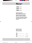
3. Installing the Decoder
Wiring the motor
Remove the soldered connection between
the motor plate and the auxiliary coil as per
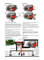
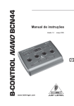
3. Einbau des Decoders
figure 1. Remove all other wires from the moAnschluss des Motors
tor plate and the auxiliary coil. Only the RFI
Gemäß Abbildung 1 löten Sie die Verbindung suppression components (chokes, capacizwischen dem Motorschild und der Feldspule tors) remain. The two individual wires from
am Motorschild ab. Entfernen Sie alle ande- the auxiliary coil have to be soldered together. Insulate the ends of these wires; they are
ren Leitungsverbindungen vom Motorschild
not required for running the motor any more.
und der Feldspule. Lediglich die Entstörelemente (Drosselspulen, Kondensatoren) ver- The wires from the decoder are to be conbleiben am Motor. Die beiden Einzeldrähte
nected as per figure 2:
des Leitungsendes von der Feldspule müsthe two white wires to the remaining wires
sen miteinander verlötet bleiben. Isolieren
of the auxiliary coil
Sie dieses Leitungsende. Es wird für den Bethe green and blue wires to the two
trieb mit dem Decoder nicht mehr benötigt.
available contacts on the motor plate
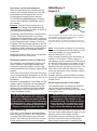
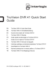
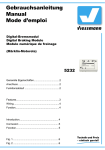
Die Leitungen des Decoders werden wie
the
brown wire to the chassis
folgt angeschlossen (Abbildung 2):
the
red wire directly to the centre pick-up
die beiden weißen Leitungen an die freien
Zuleitungen zur Feldspule
Connecting the headlights
die grüne und die blaue Leitung an die
beiden freien Anschlüsse am Motorschild Connect the grey wire to the forward headlights and the yellow one to the rear headdie braune Leitung an Fahrzeugmasse
lights. For non-directional lighting connect
die rote Leitung direkt an den Schleifer
the grey and yellow wires with each other.
3
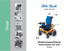
Abbildung 1
Figure 1
1
2
3
Lackisolierung
entfernen
4
remove
varnish
isolation
Anschluss der Lichtfunktion
Schließen Sie die graue Leitung an die vordere und die gelbe Leitung an die rückwärtige Beleuchtung an. Für fahrtrichtungsunabhängiges Schalten müssen die gelbe und die
graue Leitung miteinander verbunden werden.
Der zweite Pol der Lampen bleibt mit dem
Chassis verbunden.
Probieren Sie aus, ob die Fahrtrichtung
stimmt. Sollten die Lämpchen nicht der
Fahrtrichtung entsprechend leuchten, muss
die Laufrichtung des Motors geändert werden, indem die grüne und die blaue Motorleitung gegeneinander getauscht werden.
The second pole of the lights remains connected to the chassis.
Check if the headlights correspond with the
direction of travel. Should they work the
wrong way round please change the polarity
of the motor by swapping the green and the
blue wires.
Wiring auxiliary functions
Instead of the incandescent lamps for the
headlights other loads (e.g. a smoke generator) may be connected to the lighting outputs.
The outputs can be connected for non-directional function.
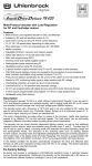
Abbildung 2
Figure 2
weiß (Feldspule)
white (field coil)
Decoder 5247
Decoder 5247
grau (Licht vorne)
gray (front light)
Masse
(Chassis)
ground
(chassis)
weiß (Feldspule)
white (field coil)
Motor
motor
blau (Motorschild)
blue (motor shield)
grün (Motorschild)
green (motor shield)
gelb (Licht hinten) yellow (back light)
braun (Masse)
brown (ground)
Licht vorne
front light
Masse
(Chassis)
4
ground
(chassis)
rot (Mittelschleifer)
red (center pick-up)
Licht hinten
back light
Masse
(Chassis)
Verbindung zum Motor auftrennen,
beide Drähte verlöten und isolieren.
Detach the connection to the motor,
solder both wires
together and
isolate them.
ground
(chassis)
Anschluss von Sonderfunktionen
Statt der Glühlampen für die Beleuchtung
können auch andere Verbraucher (wie beispielsweise ein Rauchgenerator) an die
Lichtausgänge angeschlossen werden.
Für fahrtrichtungsunabhängiges Schalten
können die Ausgänge miteinander verbunden werden.
Hinweis: Falls die Fahrtrichtung der Lok
nicht mit der Anzeige Ihrer Digitalzentrale
übereinstimmt, können Sie über CV 29 Bit 0
die Fahrtrichtung umkehren.
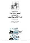
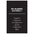
Zusätzliche Sonderfunktionen wie Rauchgenerator, Telexkupplung oder eine Führerstandsbeleuchtung können an die Funktionsausgänge A1 und A2 (Lötpunkte, siehe Abbildung 3) angeschlossen werden. Die Zuleitung des Verbrauchers wird direkt an die Decoderplatine angelötet. Die Rückleitung wird
entweder mit dem schwarzen Kabel des Decoders oder mit dem Lokchassis (Masse)
verbunden.
Passendes Kabel finden Sie im LokdecoderEinbauset 6819 von Viessmann.
Befestigung des Decoders im Fahrzeug
Der Decoder hat ein Befestigungsloch und
kann in Märklin-Fahrzeugen anstelle des
Fahrtrichtungsumschaltrelais mit der Originalschraube direkt am Chassis angeschraubt
werden.
Falls dies nicht möglich sein sollte, benutzen
Sie ein doppelseitiges Klebepad, um den Decoder an einer beliebigen Stelle in der Lok zu
befestigen.
Befinden sich Metallteile in der Nähe des Decoders, kleben Sie diese mit Isolierband ab.
Wickeln Sie den Decoder aber nicht in Isolierband ein, da dadurch die Wärmeabfuhr
behindert wird. Der Decoder kann so thermisch überlastet werden.
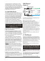
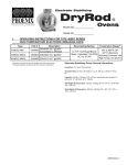
Abbildung 3
Figure 3
A1
A2
Auf der Oberseite des Decoders, direkt neben der Aussparung, befinden sich die beiden Lötpunkte für A1 und A2 für
den Anschluss zusätzlicher Funktionen.
The solder points for A1 and A2 for auxiliary functions are
located on the upper side of the circuit board next to the cutout.
Note: If the direction of travel of your engine
does not correspond with the display on your
command station, you can change the
direction with Bit 0 in CV 29.
Other auxiliary functions such as smoke generators, un-couplers (“Telex coupler”) or
cab lighting may be connected to the outputs
A1 and A2 (solder points are shown in figure
3). The wire connecting the load has to be
soldered onto the decoder circuit board. The
other wire of the load can either be connected to the black wire of the decoder or directly to the chassis.
Suitable wires are supplied with the installation set for mobile decoders Viessmann part
number 6819.
Mounting the decoder in the model
The decoder has a mounting hole and thus
can be fixed to the chassis in Märklin
engines instead of the directional relay using
the original screw.
Die Bauteile des Decoders dürfen auf
keinen Fall Metallteile des Lokfahrgestells oder Gehäuses berühren. Die Motoranschlüsse dürfen keine Verbindung
zu Mittelschleifer oder Lokfahrgestell haben. Dadurch verursachte Kurzschlüsse
führen zur Zerstörung des Decoders.
Under no circumstances should
components of the decoder touch any
metal parts of the chassis or the
locomotive body. The motor terminals
must not have any connections to the
center pick-up or chassis. Resulting
short circuits will destroy the decoder.
Motor-Entstörung
Fährt die Lok mit falscher Geschwindigkeit
oder wechselt sie plötzlich die Fahrtrichtung,
so ist die Datenübertragung zum Decoder
gestört. Der Lokmotor ist nicht oder unzureichend entstört und muss mit den entspre-
Should this not be possible for whatever reason use double sided adhesive tape to fix the
decoder at the most suitable location.
Should there be any metal parts close to the
decoder cover them with insulating tape.
Never wrap the decoder in insulating tape
5
chenden Bauteilen nachgerüstet werden.
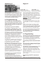
Gemäß Abbildung 4 wird zwischen die beiden Zuleitungen des Motors ein Kondensator
100 nF eingelötet und in jede Zuleitung vom
Decoder zum Motor eine Drosselspule 10 µH
eingefügt. Die entsprechenden Bauteile
liegen diesem Decoder bei.
4. Inbetriebnahme
Überprüfen Sie den korrekten Einbau mit einem Durchgangsprüfer oder einem Ohmmeter. Achten Sie bei der Platzierung des Bausteins im Fahrzeug darauf, dass nirgendwo
eine leitende Verbindung entsteht! Stellen
Sie sicher, dass auch nach Schließen der
Lok keine Kurzschlüsse entstehen können
und keine Kabel eingeklemmt werden.
Vergewissern Sie sich nochmals, dass der
Decoder oder seine Anschlüsse keine Berührung mit metallisch leitenden Flächen haben!
Ein Kurzschluss im Bereich von Motor,
Beleuchtung, Schleifer und Radsätzen
zerstört den Baustein und eventuell die
Elektronik der Lok!
Anschluss des LISSY-Sendemoduls
68400 von Uhlenbrock
Falls kein Soundmodul benutzt wird, kann
das LISSY-Sendemodul 68400 von Uhlenbrock in die SUSI-Schnittstelle eingesteckt
werden. Zum Betrieb des Moduls muss dann
Bit 1 von CV 49 auf den Wert 1 gesetzt werden (siehe Abschnitt 5).
Sollen gleichzeitig ein SUSI-Soundmodul
und das LISSY-Sendemodul an einem Decoder betrieben werden, so wird das Soundmodul immer über die SUSI-Schnittstelle angeschlossen und das LISSY-Sendemodul
immer über die in der Abbildung 5 gezeigten
Lötpunkte angeschlossen.
Wichtig: Da die beiden Bausteine unterschiedliche Befehle erhalten, ist ein gemeinsamer Anschluss an die SUSI-Schnittstelle
unter Verwendung eines SUSI-Verteilers leider nicht möglich.
Für den Betrieb des Sendemoduls an den
Lötpunkten muss Bit 1 von CV 49 auf den
Wert 0 gesetzt werden (Werkseinstellung).
Abbildung 4
Figure 4
Drosselspule 10 µH
choke coil 10 µH
grün green
M
Motor
motor
Kondensator
100 nF
capacitor
100 nF
zum
Decoder
to the
decoder
blau blue
Drosselspule 10 µH
choke coil 10 µH
since this may impair heat dissipation and
lead to thermal overload.
RFI suppression for the motor
Should the engine run with the “wrong”
speed or suddenly change its direction the
data transfer to the decoder is distorted.
The motor is not or not sufficiently equipped
for RFI suppression and has to be upgraded
with the appropriate components.
As per figure 4 a capacitor with 100 nF has
to be soldered between the motor leads and
a choke with 10 µH has to be soldered into
each motor lead.
The necessary parts are supplied with the
decoder.
4. Starting up
Check the correctness of the wiring with an
Ohm meter. When placing the module in the
engine please make sure that there are no
unintended electrical connections! Also make
certain that there are no short circuits or
squeezed wires after replacing the body on
the chassis.
Double check for any unintended contact
with metal parts!
A short circuit of the motor, the lights,
the centre pick-up or the wheels will
destroy the decoder and possibly other
electronic components of the engine!
Wiring the Uhlenbrock LISSY transmitter
68400
If no sound module is used you can connect
Digitaler und analoger Fahrbetrieb
Auf digitalen Anlagen lässt sich der Decoder the Uhlenbrock LISSY transmitter 68400 to
im Motorola- oder DCC-Datenformat steuern. the SUSI-interface. Set Bit 1 in CV 49 to “1”
Für den DCC-Betrieb sind 28 Fahrstufen vor- (also refer to chapter 5).
Should you want to connect both a SUSI
eingestellt.
6
Abbildung 5
Figure 5
1 + 20 V (rot)
2 Signal LISSY (blau)
3 Decodermasse (schwarz)
Wird der Decoder auf konventionellen Anlagen eingesetzt, so kann er entweder mit einem Wechselspannungstrafo (System Märklin) oder mit einem Gleichstromfahrgerät gesteuert werden. Alle Betriebsarten werden
vom Decoder automatisch erkannt.
5. Programmierung
+ 20 V (red)
signal LISSY (blue)
decoder ground (black)
sound module and a LISSY transmitter to
the decoder always connect the sound module to the SUSI interface. The leads of the
LISSY transmitter can be soldered to the soldering points as shown in figure 5.
Important: Since the modules receive different commands they cannot be connected
via a SUSI distributor.
For operating the transmitter via the solder
points set Bit 1 in CV 49 to ”0” (factory preset).
Die Grundlage aller Einstellmöglichkeiten
des Decoders bilden die Konfigurationsvariablen (CVs) gemäß der DCC-Norm. Der Decoder kann mit der Intellibox von Uhlenbrock,
Digital and analogue operating modes
Märklin-Motorola- oder DCC-Zentralen programmiert werden.
The decoder can be operated with Motorola
or DCC command stations. For DCC mode
Programmierung mit der Intellibox
the decoder is pre-set to 28 speed steps.
Wir empfehlen, unabhängig davon, in welOn conventional analogue layouts the decochem Format später gefahren werden soll,
der may be operated with AC (Märklin) or
den Decoder immer über das ProgrammierDC. All operating modes are automatically
menü für DCC-Decoder zu programmieren.
detected by the decoder.
Die Intellibox unterstützt die Programmierung
von DCC-Decodern mit einem komfortablen
5. Programming
Eingabemenü. Lange Adressen müssen
nicht mühsam ausgerechnet werden, sie
The basis for setting decoder parameters are
können direkt eingegeben werden. Die Intel- the configuration variables (CVs) as per the
libox errechnet automatisch die Werte für CV DCC standards. Programming is possible
17 und CV 18.
with the Uhlenbrock Intellibox, Märklin-Motorola- or DCC-command stations.
Zum genauen Vorgehen lesen Sie bitte das
zugehörige Kapitel im Intellibox-Handbuch.
Programming with the Uhlenbrock Intellibox
Programmierung mit DCC-Geräten
We recommend to always use the DCC proBenutzen Sie das Programmiermenü Ihrer
DCC-Zentrale, um die Decoder CVs per Re- gramming mode regardless of which system
is used for operation.
gister-, CV-direkt- oder Page-Programmierung auszulesen und zu programmieren. Es The Intellibox supports programming of DCC
ist ebenfalls möglich, den Decoder per
decoders with a comfortable data entry
Hauptgleisprogrammierung mit einer DCCmenu. You do not have to compute long
Digitalzentrale zu programmieren.
addresses, simply enter them directly. The
Die genaue Vorgehensweise entnehmen Sie Intellibox automatically computes the values
for CV 17 and CV 18.
bitte dem Handbuch Ihrer DCC-Zentrale.
Please refer to the user manual of the Intellibox for details.
Programmierung von langen Adressen
ohne Programmiermenü
Programming with DCC command staWird die Programmierung mit Zentralen
durchgeführt, die die Programmierung nicht tions
mit einem Eingabemenü unterstützen, müs- Make use of the programming menu of your
7
sen der Wert für CV 17 und CV 18 errechnet
werden. Hier beispielhaft die Anleitung zur
Programmierung der Adresse 2.000:
Teilen Sie den Adresswert durch 256
(2.000 : 256 = 7 Rest 208).
Nehmen Sie das Ganzzahlergebnis (hier
7) und addieren Sie 192 hinzu.
Tragen Sie das Ergebnis (199) als Wert in
CV 17 ein.
Tragen Sie den Rest (208) als Wert in CV
18 ein.
Wichtig: Setzen Sie Bit 5 von CV 29 auf
"1", damit der Decoder die lange Adresse
auch benutzt.
Werte für die CVs errechnen
Über die CVs 29 und 49 lassen sich verschiedene Einstellungen am Decoder vornehmen. Der einzugebende Wert errechnet
sich aus der CV-Tabelle, indem die Werte
der gewünschten Funktionen addiert werden.
Beispiel
Normale Fahrtrichtung
Wert = 0
28 Fahrstufen
Wert = 2
autom. Analog-/Digitalumschaltung Wert = 4
Fahrstufen über CV 2, 5, 6
Wert = 0
Kurze Adresse
Wert = 0
Die Summe aller Werte ist 6.
Dieser Wert ist als Voreinstellung ab Werk in
CV 29 abgelegt.
Programmierung mit einer Märklin-Zentrale
Mit einer Märklin-Zentrale können alle CVs
programmiert, aber nicht gelesen werden.
1. Zentrale aus- und einschalten.
2. Adresse des Decoders anwählen und
Licht einschalten.
3. Die Fahrtrichtungsumschaltung 5 x direkt
hintereinander betätigen.
4. Jetzt blinkt die hintere Beleuchtung 4 x
langsam.
5. An der Zentrale die Nummer der zu programmierenden CV wie eine Lokadresse
eingeben.
6. Die Fahrtrichtungsumschaltung kurz betätigen. Jetzt blinkt die hintere Beleuchtung
4 x schnell.
7. Den gewünschten Wert für die CV wie eine Lokadresse an der Zentrale eingeben.
8. Die Fahrtrichtungsumschaltung kurz betä-
8
DCC command station for reading and setting decoder parameters (CVs) either per
Register Mode, CV-Direct or Page Programming. It is also possible to program the decoder “on the main” with a DCC command station.
Details are described in the user manual of
your DCC command station.
Programming of long addresses without
the programming menu
Should you program the decoder with a command station that does not support programming with a data entry menu you must calculate the values for CV 17 and CV 18. The following is an example of how to do this for address 2,000:
Divide the desired address by 256
(2,000 : 256 = 7 with 208 remaining).
Take the result (whole number only, here
7) and add 192.
Enter the result (199) into CV 17.
Enter the remainder (208) as value in CV
18.
·Important: Set Bit 5 in CV 29 to “1” to
assure that the decoder responds to the
long address.
Computing values for CVs
Via CV 29 and CV 49 several settings may
be accomplished. The value to be entered is
calculated from the CV-table in which the desired functions have to be added up.
Example
Normal direction of travel
Value = 0
28 speed steps
Value = 2
automatic detection of
analogue / digital mode
Value = 4
speed curve via CV 2, 5, 6
Value = 0
short address
Value = 0
The sum of all values is 6.
This value is factory pre-set in CV 29.
Programming with a Märklin central unit
With a Märklin central unit you can program
all CVs, but you cannot read them.
1. Switch the central unit off and on again.
2. Call up the decoder address and turn on
lights.
3. Activate change of direction 5-times in a
row.
CV 29
Bit*) Bedeutung
Bit*)
0 Fahrtrichtung normal
Fahrtrichtung invers
1 14 Fahrstufen (bzw. auch für 27 Fahrstufen)
28/128 Fahrstufen
2 nur Digitalbetrieb
automatische Analog-/Digitalumschaltung
4 Geschwindigkeitskennlinie aus CV 2, 5, 6
Geschwindigkeitstabelle aus CV 67 - 94
5 Basisadresse (CV 1) nutzen
Erweiterte Adresse (CV 17, 18) nutzen
Description
Bit-Wert CV-Wert
Bit value CV value
normal direction of travel
0
0
reverse direction of travel
1
1
14/27 speed step mode
0
0
28/128 speed step mode
1
2
no DC analogue operation
0
0
autom. DC analogue detection
1
4
form speed curve with CV 2, 5, 6
0
0
use speed table (CV 67 - 94)
1
16
use primary address (CV 1)
0
0
use extended address CV 17, 18
1
32
*) Bei Lenz digital plus werden die Bits entgegen der
NMRA-Norm von 1 bis 8 nummeriert. Das ist im Bit-Programmiermodus zu beachten.
*) Lenz digital plus system version 2.0 counts the Bits in reverse order from 1 to 8 unlike the NMRA standard. This
must be observed when programming in the Bit-mode.
tigen. Jetzt blinkt die hintere Beleuchtung
4 x langsam.
Falls weitere CVs programmiert werden sollen, Punkt 5 - 8 wiederholen.
Wenn die Programmierung beendet werden
soll, die Zentrale auf „STOP“ schalten oder
die Adresse „80“ eingeben und kurz die
Fahrtrichtungsumschaltung betätigen.
Da bei der Programmierung mit einer Motorola-Digitalzentrale von Märklin nur Eingaben
von „01“ bis „80“ möglich sind, muss der
Wert „0“ über die „80“ eingegeben werden.
4. Now the rear lights slowly blink 4-times.
5. Enter the CV to be programmed as if it
was an address.
6. Activate change of direction briefly. Now
the rear lights blink fast (4-times).
7. Enter the desired value for the CV as if it
was an address at the command station.
8. Activate change of direction briefly. Now
the rear lights blink slowly (4-times).
For programming other CVs repeat steps 5
to 8.
For leaving the programming mode set the
central unit to “STOP” or enter address “80”
and activate change of direction briefly.
Since the Märklin central unit with the Motorola format only permits entries from “01” to
“80”, the value “0” has to be entered as “80”.
Page-Register zur Eingabe von CV-Nummern größer „79“
CV-Adressen größer als „79“ können nur mit
Hilfe des Page-Registers programmiert werden.
Dieses Page-Register ist die CV 66. Wird die
CV 66 mit einem Wert größer „0“ beschrieben, so wird bei allen nachfolgenden Programmiervorgängen der Inhalt der CV 66
mal „64“ zu jedem folgenden eingegebenen
Adresswert hinzuaddiert. Der eingegebene
Wert muss im Bereich „1“ bis „64“ liegen.
Mit Verlassen des Motorola-Programmiermodus wird das Page-Register (CV 66) automatisch wieder zu Null gesetzt.
Beispiel
Soll die CV 82 mit dem Wert „15“ programmiert werden, so muss zuerst die CV 66 mit
dem Wert „1“ programmiert werden.
Anschließend kann die CV 18 mit dem Wert
„15“ programmiert werden. Im Decoder wird
jetzt der Wert „15“ in der CV 82 abgelegt, die
sich aus der Addition des Inhalts der CV 66
(im Beispiel „1“) multipliziert mit „64“ (also
„64“) und der eingegebenen CV-Adresse an
der Zentrale („18“) ergibt.
Page Register for entry of CV-numbers
greater than „79“
CV addresses greater than “79” can only be
programmed with the aid of the Page Register.
This Page Register is in CV 66. If a value
greater than “0” is entered into CV 66 then
the content of CV 66 is increased by adding
“64” in all following programming steps. The
value entered must be in the range between
“1” and “64”.
When exiting the Motorola programming
mode the Page Register (CV 66) is automatically set back to “0”.
Example
If you want to set CV 82 to “15” then you first
have to set CV 66 to value “1”.
Then CV 18 can be set to value “15”. The
value “15” is now stored in CV 82, that is the
9
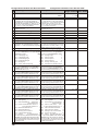
Konfigurationsvariablen des Decoders 5247
Configuration Variables of the Decoder 5247
CV Bedeutung
Description
Wertebereich StandardRange of Values wert / Value
#
1 Basisadresse
primary address
Mot.
1 - 80
1
DCC
1 - 127
2 minimale Geschwindigkeit
start speed
1 - 63
2
3 Anfahrverzögerung
acceleration adjustment
1 - 63
2
"1" bedeutet, alle 5 ms wird die aktuelle Geschwindigkeit um "1" erhöht. Beträgt die interne
maximale Geschwindigkeit z. B. "200" (CV 5 = 50
oder CV 94 = 200), dann beträgt die Anfahrzeit
von "0" auf vmax genau eine Sekunde.
4 Bremsverzögerung
5
6
7
8
17
18
19
"1" means that all 5 ms the actual speed is
increased by "1". If, for example, the internal
maximum speed is "200" (CV 5 = 50 or
CV 94 = 200), the acceleration time from "0"
to vmax is exactly one second.
deceleration adjustment
Zeitfaktor wie CV 3
time factor like CV 3
maximale Geschwindigkeit
mittlere Geschwindigkeit
Versionsnummer
Herstelleridentnummer
Lange Adresse, höherwertiger Teil
Lange Adresse, niederwertiger Teil
Consistadresse (für Doppeltraktion)
maximum speed
medium speed
manufacturer version number
manufacturer ID number
extended address, upper part
extended address, lower part
consist address
1 - 63
2
1 - 63
1 - 63
192 - 231
0 - 255
1 - 127
63
31
> 14
109
199
208
0
0 - 63
0 - 63
6
1
0 - 63
2
0 - 63
4
0 - 63
8
0 - 63
16
0 - 63
32
0 - 63
0
0 - 63
0
0 - 255
128
"0" bedeutet, die Consistadresse ist nicht aktiv.
"0" means, the consist address is not used
Wenn Bit 7 = 1, wird die Fahrtrichtung umgekehrt. (the unit is not in a consist). If Bit 7 = 1, the
relative direction of this unit is opposite.
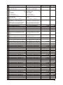
29 Konfigurationsregister (s. Seite 9) configuration register (page 9)
33 Zuordnung der Funktionsausgänge, mapping of the function outputs
die mit der Lichtfunktion (function) bei Vorwärtsfahrt aktiviert werden:
Wert
Bit 0 Lichtausgang vorn
1
Bit 1 Lichtausgang hinten
2
Bit 2 Funktionsausgang A1
4
Bit 3 Funktionsausgang A2
8
Bit 4 Rangiergang
16
Bit 5 Anfahr- / Bremsverzögerung
32
which are activated by the light function
("function") in forward direction value
Bit 0 front light output
1
Bit 1 back light output
2
Bit 2 function output A1
4
Bit 3 function output A2
8
Bit 4 shunting / switching gear
16
Bit 5 deceleration-acceleration delay32
34 Zuordnung der Funktionsausgänge, mapping of the function outputs
die mit der Lichtfunktion (function) bei Rückwärtsfahrt aktiviert werden. Zur Belegung der
einzelnen Bits siehe CV 33.
which are activated by the light function
("function") in backward direction. Regarding the meaning of the bits refer to CV 33.
35 Zuordnung der Funktionsausgänge, mapping of the function outputs
die mit der Funktionstaste F1 aktiviert werden.
Zur Belegung der einzelnen Bits siehe CV 33.
which are activated by the function key F1.
For the meaning of the bits refer to CV 33.
36 Zuordnung der Funktionsausgänge, mapping of the function outputs
die mit der Funktionstaste F2 aktiviert werden.
Zur Belegung der einzelnen Bits siehe CV 33.
which are activated by the function key F2.
For the meaning of the bits refer to CV 33.
37 Zuordnung der Funktionsausgänge, mapping of the function outputs
die mit der Funktionstaste F3 aktiviert werden.
Zur Belegung der einzelnen Bits siehe CV 33.
which are activated by the function key F3.
For the meaning of the bits refer to CV 33.
38 Zuordnung der Funktionsausgänge, mapping of the function outputs
die mit der Funktionstaste F4 aktiviert werden.
Zur Belegung der einzelnen Bits siehe CV 33.
which are activated by the function key F4.
For the meaning of the bits refer to CV 33.
39 Zuordnung der Funktionsausgänge, mapping of the function outputs
die mit der Funktionstaste F5 aktiviert werden.
Zur Belegung der einzelnen Bits siehe CV 33.
which are activated by the function key F5.
For the meaning of the bits refer to CV 33.
40 Zuordnung der Funktionsausgänge, mapping of the function outputs
die mit der Funktionstaste F6 aktiviert werden.
Zur Belegung der einzelnen Bits siehe CV 33.
49 Lokdecoder-Konfiguration
Wert
Motorregelung
aus
1
SUSI-Schnittstelle für
Soundmodul
0
LISSY-Sendemodul
2
Bit 2 bremst im Bremsabschnitt bis auf "0"
0
bis auf Fahrstufe gemäß CV 2
4
Bit 3 Datenformat Motorola aus
8
Bit 4 Datenformat DCC aus
16
Bit 5 Dimmung für A1 und A2 an
32
Bit 6 Lichtanschlüsse tauschen
64
Bit 7 bremsen
nur mit Bremssignal
0
mit Gleichspannung (Märklin-Bremsstrecke) 128
Achtung! Wenn beide Datenformate über Bit 3
und Bit 4 ausgeschaltet sind, erhält der Decoder
keine Fahrbefehle mehr und kann nur noch programmiert werden.
Bit 0
Bit 1
10
which are activated by the function key F6.
For the meaning of the bits refer to CV 33.
loco decoder configuration
value
motor regulation
off
1
SUSI interface for sound module
0
LISSY transmitter
2
Bit 2 brakes in brake section
to "0"
0
to speed step like defined in CV 2
4
Bit 3 data format Motorola disabled
8
Bit 4 data format DCC disabled
16
Bit 5 dimming for A1 and A2 enabled
32
Bit 6 swap the light outputs
64
Bit 7 braking
only with brake signal
0
only with DC (Märklin brake section) 128
Caution! If both data formats are disabled
via Bit 3 and Bit 4, the decoder won't receive
any further driving instructions and it is only
possible to reprogram it.
Bit 0
Bit 1
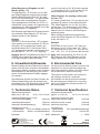
CV Bedeutung
#
50 Dimmung der Funktionsausgänge
A1, A2 und Licht
51 Einstellung der analogen BetriebsWert
art:
nur AC-Betrieb
nur DC-Betrieb
AC- und DC-Betrieb
mit automatischer Erkennung
dimming of the function
outputs A1, A2 and light
settings for the analogue
operating mode
1 only AC operation
2 only DC operation
3 AC and DC operation
with automatic identification
52 Geschwindigkeit am Ende der
Bremsstrecke
Gültig, wenn CV 49 Bit 2 = 1 und Bit 7 = 1.
53 Wiederholrate der Motorregelung
54
55
56
57
58
59
Description
Wertebereich StandardRange of values wert / value
0 - 63
32
1-
3
1
1 - 255
30
1 - 255
150
1 - 255
1 - 255
1 - 127
0 - 255
0, 1
130
30
48
10
25
0
0 , 250
250
value
1
2
3
speed at the end of the brake
section
Valid, if CV 49 Bit 2 = 1 and Bit 7 = 1.
motor regulation repetition rate
(CV 49 Bit 0 = 1) Rate = Wert x 53 µs
Hinweis: Sollte die Lok nicht gleichmäßig fahren,
so kann dieser Parameter verändert werden.
Werte zwischen 60 und 255 sind sinnvoll.
(CV 49 Bit 0 = 1) rate = value x 53 µs
Advice: If the locomotive doesn't drive consistently, this parameter can be changed.
Values between 60 and 255 are useful.
Motorreglerparameter 1
Motorreglerparameter 2
Skalierung Motor-EMK-Spannung
Motorreglerparameter 3
Zeitschlitz für AD-Wandlermessung
Reset auf die Werkseinstellungen
motor control parameter 1
motor control parameter 2
scaling of the motor's back EMF
motor control parameter 3
time slot for AD converter meas.
reset to the factory settings
Wird diese CV auf "1" programmiert, so wird der
Decoder auf seine Werkseinstellungen zurückgesetzt.
If this CV is programmed to "1", all CVs of
the decoder are set back to their default
factory values.
60 Kurzschlussüberwachung (nicht än- short circuit supervision (don't
dern!) 0 = ausgeschaltet, 250 = eingeschaltet change!) 0 = off, 250 = on
61 Abschalttemperatur in °C
switch-off temperature in °C
65 Offset-Register für die CV-Program- offset register for CV programmierung mit einer Motorola-Zentrale ming with Motorola central units
66 Page-Register für die CV-Program- page register for CV programmierung mit einer Motorola-Zentrale ming with Motorola central units
67 Kennlinienwert für Fahrstufe 1
speed value for speed step 1
68 Kennlinienwert für Fahrstufe 2
speed value for speed step 2
69 Kennlinienwert für Fahrstufe 3
speed value for speed step 3
70 Kennlinienwert für Fahrstufe 4
speed value for speed step 4
71 Kennlinienwert für Fahrstufe 5
speed value for speed step 5
72 Kennlinienwert für Fahrstufe 6
speed value for speed step 6
73 Kennlinienwert für Fahrstufe 7
speed value for speed step 7
74 Kennlinienwert für Fahrstufe 8
speed value for speed step 8
75 Kennlinienwert für Fahrstufe 9
speed value for speed step 9
76 Kennlinienwert für Fahrstufe 10
speed value for speed step 10
77 Kennlinienwert für Fahrstufe 11
speed value for speed step 11
78 Kennlinienwert für Fahrstufe 12
speed value for speed step 12
79 Kennlinienwert für Fahrstufe 13
speed value for speed step 13
80 Kennlinienwert für Fahrstufe 14
speed value for speed step 14
81 Kennlinienwert für Fahrstufe 15
speed value for speed step 15
82 Kennlinienwert für Fahrstufe 16
speed value for speed step 16
83 Kennlinienwert für Fahrstufe 17
speed value for speed step 17
84 Kennlinienwert für Fahrstufe 18
speed value for speed step 18
85 Kennlinienwert für Fahrstufe 19
speed value for speed step 19
86 Kennlinienwert für Fahrstufe 20
speed value for speed step 20
87 Kennlinienwert für Fahrstufe 21
speed value for speed step 21
88 Kennlinienwert für Fahrstufe 22
speed value for speed step 22
89 Kennlinienwert für Fahrstufe 23
speed value for speed step 23
90 Kennlinienwert für Fahrstufe 24
speed value for speed step 24
91 Kennlinienwert für Fahrstufe 25
speed value for speed step 25
92 Kennlinienwert für Fahrstufe 26
speed value for speed step 26
93 Kennlinienwert für Fahrstufe 27
speed value for speed step 27
94 Kennlinienwert für Fahrstufe 28
speed value for speed step 28
115 Zugkategorie für LISSY
train category for LISSY
0 - 255 verschieden
0 - 255
0
0 - 255
0
0 - 255
0 - 255
0 - 255
0 - 255
0 - 255
0 - 255
0 - 255
0 - 255
0 - 255
0 - 255
0 - 255
0 - 255
0 - 255
0 - 255
0 - 255
0 - 255
0 - 255
0 - 255
0 - 255
0 - 255
0 - 255
0 - 255
0 - 255
0 - 255
0 - 255
0 - 255
0 - 255
0 - 255
1- 4
5
7
10
12
15
17
20
22
25
27
30
32
35
37
42
50
55
60
65
70
75
80
85
90
95
100
105
110
1
11
Offset-Register zur Eingabe von CVWerten größer „79“
CV-Werte größer „79“ können nur mit Hilfe
des Offset-Registers programmiert werden.
Dieses Offset-Register ist die CV 65. Wird
die CV 65 mit einem Wert > „0“ beschrieben,
so wird bei allen nachfolgenden Programmiervorgängen der Inhalt der CV 65 mit „4“
multipliziert und zu jedem im Folgenden programmieren CV-Wert hinzuaddiert und in der
entsprechenden CV abgelegt.
Mit Verlassen des Motorola-Programmiermodus wird das Offset-Register (CV 65) automatisch wieder zu Null gesetzt.
result of the value of CV 66 (in this example
“1”) multiplied by “64” (= 64) and the CV address entered at the central unit (“18”).
Offset Register for entering values greater than “79”
CV values greater than “79” can also be programmed by means of the Offset Register.
This Offset Register is in CV 65. If a value
greater than “0” is entered into CV 65 then
the content of CV 65 is multiplied by “4” and
added to the CV values in all following programming steps.
When exiting the Motorola programming
mode the Offset Register (CV 65) is automatically set back to “0”.
Beispiel
Soll die CV 49 mit dem Wert „157“ programmiert werden, so muss zuerst die CV 65 mit
dem Wert „25“ programmiert werden. Anschließend kann die CV 49 mit dem Wert
„57“ programmiert werden. Im Decoder wird
jetzt der Wert 4 * 25 + 57 = 157 abgelegt.
Hinweis: Bei der Programmierung der CV 65
und der CV 66 bleibt der Inhalt von Off-setund Page-Register unberücksichtigt.
Example
If you want to set CV 49 to “157” then you
first have to set CV 65 to value “25”. Then
CV 49 can be set to value “57”. Now the value 4 * 25 + 57 = 157 is stored in the decoder.
Note: when programming CV 65 or CV 66
the content of the Offset Register and the
Page Register are not taken into account.
6. Umweltschutzhinweise
6. Environmental Care
Dieses Produkt darf am Ende seiner Lebensdauer nicht über den normalen Haushaltsabfall entsorgt werden, sondern muss an einem
Sammelpunkt für das Recycling von elektrischen und elektronischen Geräten abgegeben werden.
Das Mülleimer-Symbol auf dem Produkt, der
Gebrauchsanleitung oder der Verpackung
weist darauf hin. Die Werkstoffe sind gemäß
ihrer Kennzeichnung wiederverwertbar.
At the end of its life this product cannot to be
disposed of in the household garbage but
has to be handed in where you return electrical and electronic waist for recycling.
The symbol on the product, the manual or
the package serves as a reminder.
All materials can be recycled as indicated.
By assuring proper disposal at a recycling
point you contribute to the preservation of
the environment.
7. Technische Daten
7. Technical Specifications
Maße ohne Anschlusskabel ca. (L x B x H)
33,5 x 19 x 5,5 mm³
maximale Belastung pro Lichtund Funktionsausgang
1.000 mA
maximaler Motorstrom
1.200 mA
maximale Gesamtbelastung
1.200 mA
Ansteuerung durch
- Digitalformat
DCC und Märklin-Motorola
- konventionell
Gleich- und Wechselstrom
Adressen
1 ... 9999
dimensions without wires
approx. (L x W x H)
33.5 x 19 x 5.5 mm³
maximum current per light
output and function output
1,000 mA
maximum motor current
1,200 mA
maximum total load
1,200 mA
controlling by
- digital format
DCC and Märklin-Motorola
- conventionel
AC and DC
addresses
1 ... 9999
Viessmann
Modellspielwaren GmbH
Am Bahnhof 1
D - 35116 Hatzfeld
www.viessmann-modell.de
12
gemäß
EG-Richtlinie
89/336/EWG
09/05
Stand 01
Sachnummer 92351
Märklin ist ein eingetragenes Warenzeichen der / is a registered trademark of Gebr. Märklin & Cie. GmbH, Göppingen (Germany)
Motorola ist ein eingetragenes Warenzeichen der / is a registered trademark of Motorola Inc., Tempe-Phoenix (Arizona, USA)