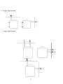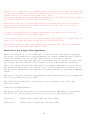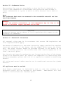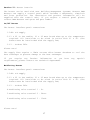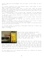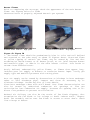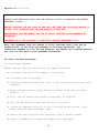
1
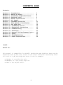
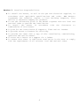
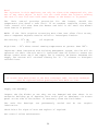
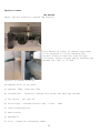
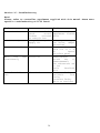
BMM Heaters Limited
Compact HM Range
Installation, Service and User Manual
Indirect gas fired warm air heater type B22, C4 & C5
Please read this document prior to the installation and servicing of this equipment.
Failure to follow these instructions can cause damage to property, injury or death to person.
Work should only be carried out by suitable qualified personnel and Corgi registered.
BMM Heaters Limited
1 Copeland Court
Forest Grove
Middlesbrough
TS2 1RN
Tel: 01642 240700
Fax: 01642 240708
Email: [email protected]
Web: www.bmmheaters.co.uk
1
CONTENTS PAGE
Contents:
Section
Section
Section
Section
Section
Section
Section
Section
Section
Section
Section
Section
Section
Section
Section
Section
Section
1: Introduction ………………………………………………
2: Health & Safety…………………………………………
3: Installers Responsibilities…………
4: Technical Data …………………………………………
5: Heater Installation ……………………………
6: Air Supply …………………………………………………
7: Overheat Protection …………………………
8: Flue System & Ventilation……………
9: Gas Pipe work …………………………………………
10: Condensate Drains ……………………………
11: Electrical Connections ………………
12: Commissioning ………………………………………
13: Servicing……………………………………………………
14: Removal and Replacement Parts……
15: Spare………………………………………………………
16: Troubleshooting…………………………
17: Users Instructions…………………
3
4
5
6
7
9
10
11
14
15
15
18
25
29
32
33
34
Model:
Serial No:
This manual is compatible for On/Off, Modulating and High/Low these can be
differentiated by the last letter in the model reference. Modulating units
will end in a (M) and High/Low units in HL for example:
•
•
•
HMA(M) is a modulating unit
HMA(HL) is a two stage high low
HMA is the On/Off model.
2
Section 1: Introduction
The instructions refer to appliances designed to operate in the UK and Ireland.
Appliances designed for other countries can be provided on request.
This appliance must be installed in accordance with the local and national codes
in force and used only in a sufficiently ventilated space, as specified in these
instructions.
Before installation, check that the local gas distribution systems, nature of gas
and pressure, and adjustment of the appliance are compatible.
When installed within the United Kingdom the total installation must comply with
the recommendations and requirements of the British Standard BS 6230:2005 “
Specification for the installation of gas-fired forced convection air heaters for
commercial and industrial space heating (2nd and 3rd family gases)”
This appliance is suitable for outside installation, if installation within a
weather proof enclosure.
Terms and Definitions
Indirect Fired
The term ‘Indirect Fired’ indicates that the products of combustion are kept
isolated from the main supply air stream. The burner fires into a combustion
chamber, the resultant products of combustion are directed into a heat exchanger
and from there to an external flue, which discharges into the atmosphere.
Factory Test
All heaters produced by BMM Heaters Ltd will be subjected to various tests before
they are dispatched. Each heater is individual so the data will differ between
each unit. The relevant data can be found on the data plate attached to the
heater.
External Heaters
The construction of the unit will consist of double skin panels and be fully water
proof: the burner compartment will be adequately ventilated via two combustion air
grills.
Burner Types
BMM Heaters Ltd will use a series of in-shot gas fired burner in multiple forms,
depending on output required. This burner will be either on/off, high/low or
modulating control.
Fuel Type
HM Compact Range are designed to work on G20 I2H Natural gas; however if this gas
is unavailable please contact us.
Flue Type
The HM Compact Range heater is approved for the following flue type:
• Type C4 & C5 – Horizontal and Vertical flue (Two piped)
• Type B22 – Vertical or horizontal flue for combustion air vents (Single
piped)
3
C & B type appliance - Internal & External installed
Combustion air
Combustion air
C - type 4 & 5 suitable for indoor and outdoor (if fitted outside this
unit must be installed within an AHU)
B-Type appliance has high and low level gills installed on the front panel, this
appliance is suitable for outdoor installation.
Section 2: Heater Safety
The Installation of this appliance must be done by a registered
installer/contractor suitably qualified in the installation and service of
gas fired heating equipment.
WARNING!
Improper installation, adjustment, alteration, service or maintenance can
result in death, injury or property damage. Read the installation,
operation and service manual thoroughly before installing or servicing this
appliance.
Note:
To Installer: Please take the time to read and understand theses
instructions prior to any work servicing or installing this appliance.
Installers must leave a copy of this manual with the end user/owner.
To Owner: This manual must be kept in a safe place in order to provide
necessary information for service engineers at a later date.
4
Section 3: Installers Responsibilities
♦ To install the heater, as well as the gas and electrical supplies, in
accordance with applicable specifications and codes. BMM Heaters
recommends the installer contact a local Building Inspector, Fire
Officer or Insurance Company for guidance.
♦ To use the information given in the manual together with the local and
national codes to perform the installation.
♦ To install the heater in accordance with the Clearances to
Combustibles of this heater.
♦ To plan for the installation of supports, flues and air intakes.
♦ To provide access to burners for servicing.
♦ To provide the owner with a copy of this installation, commissioning,
operation and service manual.
♦ To never use a heater as a support for a ladder.
♦ To ensure that there is sufficient ventilation in the area to comply
with the requirements of all relevant local and national codes.
5
Section 4: Technical Data
HMA Technical Table 1
MODEL
Nominal heat
output
Nominal heat
input
Minimum heat
output
Gas consumption
Gas connection
Min inlet gas
pressure
Max inlet gas
pressure
Burner Pressure
Injector Size
Number of tubes
Flue diameter
Combustion air
inlet
Electrical
Current (burner
only)
Net weight
Maximum air
volume
Minimum air flow
kW
35
35
50
45
60
60
70
70
85
85
95
95
kW
39
50
67
78
95
105
kW
17.5
25
30
35
42.5
47.5
m³/h
bsp
mbar
3.75
¾"
17.5
4.8
¾"
17.5
6.44
¾"
17.5
7.51
¾"
17.5
9.13
¾"
17.5
10.20
¾"
17.5
mbar
30
30
30
30
30
30
mbar
mm
#
mm
mm
8.7
2.87
4
100
100
8.7
3.16
4
100
100
8.7
3.16
5
100
100
8.7
3.16
6
100
100
8.7
3.16
7
130
130
8.7
3.16
8
130
130
volts
amps
230
3
230
3
230
3
230
3
230
3
230
3
kg
M³/sec
260
2.65
260
3.53
313
4.41
368
5.30
427
6.18
442
7.06
M³/sec
0.82
1.05
1.4
1.65
2.00
2.2
HMB Technical Table 2
MODEL
Nominal heat
output
Nominal heat
input
Minimum heat
output
Gas consumption
Gas connection
Min inlet gas
pressure
Max inlet gas
pressure
Burner Pressure
Injector sizes
Number of tubes
Flue diameter
Combustion air
inlet
Electrical
Current (burner
only)
Net weight
Maximum air
volume
Minimum air flow
•
kW
35
35
50
45
60
60
70
70
85
85
95
95
kW
39
50
67
78
95
105
kW
17.5
25
30
35
42.5
47.5
m³/h
bsp
mbar
3.75
¾"
17.5
4.8
¾"
17.5
6.44
¾"
17.5
7.51
¾"
17.5
9.13
¾"
17.5
10.20
¾"
17.5
mbar
30
30
30
30
30
30
mbar
mm
#
mm
mm
8.7
2.87
4
100
100
8.7
3.16
4
100
100
8.7
3.16
5
100
100
8.7
3.16
6
100
100
8.7
3.16
7
130
130
8.7
3.16
8
130
130
volts
amps
230
3
230
3
230
3
230
3
230
3
230
3
kg
M³/sec
245
2.65
245
3.53
293
4.41
344
5.30
401
6.18
456
7.06
M³/sec
0.82
1.05
1.4
1.65
2.00
2.2
Calculations are worked out using the calorific value 10.7 kWh/m³ - 1007 mbar – 15 °C
Each appliance has been range rated; burner pressures can be found on the data plate and
the burner pressure once commissioned must be entered in the actual.
6
Section 5: Heater Installation
This appliance must be installed in accordance with the rules in force.
Before installation, check that the local distribution conditions, nature
of gas and pressure and to make sure the appliance is compatible.
When the heater is installed within Great Britain the whole installation
must comply with the requirements and recommendations of BS 6230:2005
“Installation of gas fired forced convection air heaters for commercial and
industrial space heating”.
The air heater must be installed in accordance with the rules in force and
the relevant requirements of any fire regulations or insurance company’s
requirements appertaining to the area in which the heater is located,
particularly where special risks are involved, such as areas where petrol
vehicles are housed, where cellulose spraying is carried out, in wood
working departments etc.
Clearances and Positioning:
The following clearances for installation and servicing must be observed.
To the Front
To the Rear
To at least one side
Above the heater
Equal to the depth of the heater.
1 Metre
1 Metre
1 Metre
7
Clearances
A minimum of 500mm upstream and downstream must be allowed for, due to the
radiant heat. Filters must be fireproof, if fitted and a motor shield is
required over the main supply fan motor if directly in front of the heater.
When installing the heater, minimum clearance is required around the
heater.
If the heater is to be fitted at a height, then the structure of the gantry
must be capable of the heaters weight (which can be found in section 4,
table 1, 2), also a safe working platform and access must be allowed for;
to enable easy and safe working access.
Note: The front of the heater is the side on which the burner is fastened.
When designing a system, allowance must be made so equipment can be
serviced after installation and for the fitting of any spares, which may be
required. The BMG is designed to be installed within an Air Handling Unit
or ductwork.
The appliance is designed to work in a maximum ambient temperature of 40°c.
The Air Heaters are mounted direct on the floor and do not need any fixing.
The base on which the heater is positioned should not be less than 150mm (6
inches) thick and must be constructed of non-combustible material.
Any combustible material adjacent to the heater and the flue system must be
placed or shielded as to ensure that its temperature does not exceed 65ºC.
WARNING!
No air heater shall be installed where there is a foreseeable risk of
flammable particles, gases, vapours or corrosion inducing gases or vapours
being drawn into either the heated air stream or the air for combustion. In
such cases installation may only proceed if the air to be heated and the
air for combustion are ducted to the heater from an uncontaminated source,
preferably outside the building.
If this heater is to be suspended then the weight in table 1, 2 in section
4 must be taken into account.
8
Section 6: Air Supply
Ductwork
All delivery and return air ducts, including air filters, jointing and any
insulation or lining must be constructed entirely of materials, which will
not contribute to a fire, are of adequate strength and dimensionally stable
for the maximum internal and external temperatures to which they are to be
exposed during commissioning and normal operation.
In the selection of
materials, account must be taken of the working environment and the air
temperatures which will result when the overheat limit thermostat is being
commissioned. Where inter-joint spaces are used as duct routes, they should
be suitably lined with fire-resisting material.
A full and unobstructed return air path to the air heater must be provided.
If the air heater is to be installed in a plant room, the return air and
warm air discharge arrangements must be such as to avoid interference with
the operation of the flue by the air circulation fan. The return air intake
and the warm air outlet(s) should therefore be fully ducted, in the plant
room, to and from the heater, respectively. The openings in the structure
of the plant room through which the ducting passes must be fire stopped.
In addition, where there is a risk of combustible material being placed
close to the warm air outlets, suitable barrier rails should be provided to
prevent any combustible material being within 900mm (3 ft) of the outlets.
Airflow
It is essential that the correct amount of air is provided through the
heater and should be evenly distributed when entering the heater. All
pressure calculations/resistances for air are ambient with the heater in
the “off” position.
Adjustable by pass plates.
HM Compact models fitted into larger cabinets for internal or external use
should be fitted with adjustable air balancing plates or a simple
restriction damper. If the work is not going to be carried out by BMM
Heaters Ltd then we recommend that the installer ensures that it can be
altered to give guaranteed minimum equal air over the heat exchanger. (See
Minimum and Maximum air flow volumes in section 4 table 1, 2).
9
Section 7: Overheat Protection Device
Overheat protection is fitted in case the air flow falls below the minimum
necessary for safe operation of the heater, which may be caused by failure
of the supply fan motor or belt failure, dirty filters or inlet damper
failure. If the air flow falls too low, the high limit will trip out and
will require manually resetting. If this happens on a regular basis it must
be investigated by a competent registered engineer as this could cause
serious damage to the heater. The over heat is set 20ºc above the running
temperature after 30 minutes.
If the heater is supplied without a fan in module form then the fan stat on
the L4064 will have to be wired by others. Otherwise BMM Heaters will wire
the fan control, please see dedicated wiring diagram supplied with this
heater.
WARNING!
If the heater has a Honeywell combined thermostat installed then the jumper
link must be removed from the replacement thermostat.
Heat exchanger damage may be the result.
Failure to follow these instructions can result in death, injury, property
damage or product damage.
Once the overheat is set to the correct operating
commission engineer must seal the overheat stat.
temperature
Ensure that the fan and limit settings are as follows:Fan On
35ºc
Fan Off
25 ºc
Limit
20 ºc above normal running temperature no greater than 100 ºc
10
the
Section 8: Flue System & Ventilation
Always ensure that adequate combustion air is provided to suit the total
installation of all combustion equipment in accordance with BS6230 or
BS5440. The ventilation rates for B-Type appliances can be found on page 13
in this manual.
Flue pipe runs may be horizontal or vertical and terminate either through
the wall or roof.
The flue dia can be found in Section 4 table 1, 2
The maximum flue length of C appliances is 12 metres in total & the maximum
flue length for a B appliance is 12 metres. Note! 1 x 90º Elbow = 1metre
length and 1 x 45º bend = 500mm length
All flue pipes must be sealed. Using seamless, aluminum or stainless flue
pipe as supplied by BMM Heaters Ltd or equivalent. Please ensure that the
manufacturer’s instructions are followed.
B-Type Appliance
If the air heater is a B-Type appliance then the air for combustion will be
taken from either the room or outside via combustion air grills fitted on
the burner compartment. The installer must make sure there is adequate
ventilation and that it complies with BS6230 & BS5440; plus any other
relevant regulation & fire regulation.
All joints must be sealed to prevent products of combustion from entering
the building.
If the flue is to pass through a combustible part of a building then the
flue pipe will require a non-combustible sleeve with an air gap of at least
20mm. The flue must be installed at least 150mm away from any combustible
material.
The temperature of any combustible material must not exceed 65ºC when the
heater is in operation.
When maximum flue runs are unavoidable or when the flue is subjected to
cold air and condensation is unavoidable then provisions must be made to
remove condensation at a point to which it can be directed into a drain or
gully.
Note!
The condensate drain must be connected in Non-corrodible material not less
than 20mm diameter. Copper must not be used for condensate drains.
11
B Type Appliances
Roof Terminated.
B-Type Appliance
B-Type Appliance
Wall Terminated
C Type Appliances
Roof Terminated.
C-Type Appliance
C-Type Appliance
Roof Terminated.
C-Type Appliance
Wall Terminated
12
On both B & C type flues a terminal guard must be fitted over the terminal
if the wall terminal is below 1.8 metres from floor level and the fresh air
intake must be at least 500mm from floor level.
A terminal Guard can be provided by BMM Heaters if required, please contact
our sales office for a price and availability.
When installing as a C5-Type appliances the ducts must not be fitted on
opposite wall and must be fitted on either the same wall or a walls at
right angles to each other.
C-Type flues the distance between the exhaust terminal and fresh air
terminals must be at least 700mm apart.
If a common flue system is used the minimum size required is 200mm and the
size will increase prorata to the size of the heater flue.
Note! The fresh air duct and exhaust duct must be the same size and must
not exceed the maximum flue runs allowed.
Ventilation for B Type Flued appliances.
Where the heater is to be installed in a plant room, the heater requires
the plant room housing to have permanent air vents communicating directly
with the outside air, at a high level and at a low level. Where
communication with the outside air is possible only by means of high level
air vents, ducting down to floor level for the lower vent(s) should be
used. Air vents should have negligible resistance and must not be sited in
any position where they are likely to be easily blocked or flooded, or in
any position adjacent to an extraction system, which is carrying flammable
vapour.
Grilles or louvers should be designed so that high velocity air streams do
not occur within the plant room.
The ventilation should be installed to in accordance with local and
national codes.
Ventilation Requirements:
The space in which the heater is situated must be adequately ventilated,
see below for the minimum ventilation area at low and high levels.
Low Level:
540cm² plus 4.5cm² per kW after 60kw.
High Level:
270cm² plus 2.25cm² per kW after 60kw
13
Ventilation for C Type Flue Appliances.
No additional combustion air is required; however previsions for
ventilation to cool the plant room may be required.
Section 9: Gas Piping
All Gas Pipe-work to the appliance should be installed in accordance with
current regulations, local and national codes and must be connected with an
acceptable gas isolation valve and union, so that the burner maybe removed
to aid servicing and inspection of the burner.
Size and Connection
The following considerations are to be taken into account:
a) A union and gas ball valve must be fitted to the inlet connection on
the heater, so that the heater can be isolated or removed without
having to isolated the whole gas supply to the building.
b) Pipe work smaller than the inlet gas connection should not be used.
c) The gas supply pipe is adequately sized to carry correct volume of gas
from the gas meter to the heater(s).
d) The heat input and gas flow rates for each heater can be found in
section 4 table 1, 2, 3 and 4 to aid in the design of gas supply pipe
work.
e) All gas pipe work and electrical connections must be adequately
supported and must not support any of the heaters weight or rely on
the strength of the burner gas pipe work.
f) Unless the heater is suspended or movement is apparent, the BMM Heater
must be connected with medium, heavy or copper pipe; otherwise the use
of an approved flexible connection between the isolating valve and the
heater can be used.
We recommend that the flexi hose is one size
bigger than the heater connection to reduce any pressure loss.
The minimum inlet gas pressure for natural gas should be 20 mbar.
Please note: We require a minimum of 17.5mbar at the inlet when running and
a maximum of 75mbar, if this is exceeded then an external to the appliance
governor must be fitted.
Important: The complete installation must be purged and tested for gas
soundness in accordance with local, national codes and a registered
engineer.
The gas connection sizes can be found in section 4 Table 1, 2
14
Section 10: Condensate Drains
When maximum flue runs are unavoidable or when the flue is subjected to
cold air and condensation is unavoidable then provisions must be made to
remove condensation at a point to which it can be directed into a drain or
gully.
Note!
The condensate drain must be connected in Non-corrodible material not less
than 20mm diameter.
WARNING!
Do not use plastic connections, as the temperature may be high at the
outlet to the drain. Copper pipe must not be used.
Important
Condensing heaters may be subject to local regulations with respect to the
discharge of condensate.
Section 11: Electrical Connections
All external wiring must be in accordance with current IEE Regulations and
local regulation which apply.
The method of connection to the mains electricity supply should allow complete
electrical isolation of the heater and the supply should serve the heater
only. The mains isolator should be provided adjacent to the heater in an
easily accessible position. The isolator must have contact separation of at
least 3 mm on all poles.
The electric and controls terminations are located on the front of the Heater
housed in an interface panel. All heaters are compatible for inter-facing with
building management systems and 0-10v DC is required as standard on Modulating
heaters.
All wiring and control cables must be ran in conduit and correct size glands
used etc.
All appliances must be earthed.
Each heater manufacture is individually made to suit the customer so a
dedicated circuit will be attached to this manual.
BMM Heaters will also
attach a circuit within the interface panel.
15
Table 3: Electrical Data
Model
Motor
size
Three
phase
Motor
size
Single
phase
Motor
rated
supply
fuse
(Three
phase)
Motor
rated
supply
fuse
(Single
Phase)
Burner
Voltage
35
N/a
500 w
N/a
5 Amps
45
500w
500 w
10 Amps
5 Amps
60
750w
1.1kW
10 Amps
10 Amps
70
750w
1.1 kW
10 Amps
10 Amps
85
750w
1.1 kW
10 Amps
10 Amps
95
1.1 kW
N/a
10 Amps
10 Amps
240v 1ph
50Hz
240v 1ph
50Hz
240v 1ph
50Hz
240v 1ph
50Hz
240v 1ph
50Hz
240v 1ph
50Hz
Controls: BMM Heaters can supply controls for these heaters upon request.
Please confirm with us the type of controls prior to connecting to check
compatibility.
Note: All heaters have been electrically tested at BMM Heaters factory.
This appliance is not intended for use by persons (including children) with
reduced physical, sensory or mental capabilities, or lack of experience and
knowledge, unless they have been given supervision or instruction
concerning use of the appliance by a person responsible for their safety
16
Section 13: Heater Controls
The heater can be used with most Building Management
Heaters can supply a control panel which includes a
and frost protection. The Instruction and product
supplied with the control unit, if you require a
contact BMM Heaters and quote the part number.
Systems; However BMM
thermostat, timeclock
information will be
control panel please
On/Off Burner
The heater interface panel connections:
1. 240v & N supply
2. T1 & T2 is the enable, T1 & T2 must break when up to the temperature
required. All interlocks to be wired in series with T1 & T2. (The
burner must be interlocked with the supply fan)
3. T3 – Lockout 240v
Please note!
The supply fans require a 10min overrun after burner shutdown to cool the
heat exchanger to prevent damage to the heat exchanger.
If you require any further information or you
requirements, please contact our technical department.
have
any
special
Modulating Burner
The heater interface panel connections:
1. 240v & N supply
2. T1 & T2 is the enable; T1 & T2 must break when up to the temperature
required. All interlocks to be wired in series with T1 & T2. (The
burner must be interlocked with the supply fan)
3. T3 – Lockout 240v
4. Modulating valve terminal 1 – 0v
5. Modulating valve terminal 2 – 24vac
6. Modulating valve terminal 5 – 10vdc
Please note!
17
The supply fans require a 10min overrun after burner shutdown to cool the
heat exchanger to prevent damage to the heat exchanger.
If you require any further information or you
requirements, please contact our technical department.
have
any
special
WARNING!
Electrical Shock Hazard
Use extreme caution while working on this appliance.
Failure to follow these instructions can result in death or electric shock.
Only competent engineers should carry out work on this appliance.
Section 12: Commissioning
COMMISSIONING MUST BE CARRIED OUT BY A COMPETENT REGISTERED ENGINEER
(CORGI), ALSO TO BE USED WITH BURNER COMMISSIONING DETAIL SEE BURNER INSERT
Operating & Safety Instructions
1. This Heater does not have a pilot. It is equipped with a direct spark
ignition device that automatically lights the gas burner. DO NOT try to
light burners by hand.
2. BEFORE OPERATING, leak test all gas piping up to heater gas valve. Smell
around the unit area for gas.
DO NOT attempt to place heater in operation until source of gas leak is
identified and corrected.
3. Do not attempt to operate unit, if there is indication that any part or
control has been under water. Any control or component that has been under
water must be replaced prior to trying to start the unit.
Start-up
1. Turn thermostat or temperature controller to its lowest setting
2. Turn off gas supply at the manual shut-off valve
3. Turn off power to the unit at the disconnect switch.
4. Remove access panel or open door to unit vestibule housing the gas
heater.
5. Check the inlet pressure is a 20mbar and carry out a tightness test on
the gas pipe work; once test
is completed carry on with commissioning.
6. Open all manual gas valves
7. Turn power on
18
8. Set thermostat or controller to its highest position to initiate call
for heat and maintain operation of
unit.
9. Draft inducer will run for a 15 to 30 second pre-purge period (See
Sequence of Operation provided)
10. At the end of the pre-purge the direct spark will be energized and gas
valve will open
11. Burners ignite.
• Failure to Ignite
1. On the initial start-up or after unit has been off long periods of time,
the first ignition trial may be
unsuccessful due to need to purge air from manifold at start-up.
2. If ignition does not occur on the first trial, the gas and spark are
shut-off by the ignition control and
the control enters an inter-purge period of 15 to 90 seconds, during
which the draft inducer
continues to run.
3. At the end of the inter-purge period, another trial for ignition will be
initiated.
4. Control will initiate up to three ignition trials on a call for heat
before lockout of control occurs.
5. Control can be brought out of lockout by turning thermostat or
controller to its lowest position and
waiting
Check & Adjust Manifold Pressure
The burner pressure should be taken after the burner has been running for
ten minutes.
• For 2 stage and modulating control systems manifold pressure should be 3
mbar low fire. Adjust Lo Regulator on 2 stage gas valve, if necessary.
After that the burner high fire manifold pressure should increase to 8.75
mbar.
• For On-Off units the manifold pressure should be 8.75 mbar.
The burner pressure is adjusted by turning the multi block governor in
either a clockwise rotation to increase the pressure or in an anti
clockwise rotation to decrease the pressure. Once the pressure has been set
it must be sealed with the use of paint or temper sealant.
19
Setting the Modureg.
A.
B.
C.
D.
E.
F.
Cap
Adjustment Screw (7mm) for minimum Pressure setting
Adjustment Screw (9mm) for maximum Pressure setting
6.3 mm AMP Terminals
M5 pressure feedback connection (if used)
“O” – Ring x 2
Adjustment, checkout and maintenance
Important - Adjustments should be made by qualified persons only.
Allow time for pressure to stabilize before making adjustments.
It is recommended that the Modureg is operated a few times to ensure
correct setting.
Take care that after any adjustment cap and “o” – ring are mounted.
The maximum pressure setting must first be adjusted because any adjustment
of maximum pressure setting influences minimum pressure setting.
Adjusting maximum pressure setting (see fig 1)
• Disconnect pressure feedback connection (if applicable).
20
•
•
•
•
•
Connect a suitable pressure gauge to pipe line or to outlet pressure
tap of gas control concerned, to measure burner pressure (measuring
point must be as near to burner as possible)
Energize modulating coil, operator, set control in operation and wait
until an outlet pressure is recorded on pressure gauge.
Turn the maximum rate adjustment screw clockwise for increasing or
counter-clockwise for decreasing the maximum pressure setting if
adjustment is needed.
Check minimum pressure setting and readjust if necessary
Mount cap and “O”- ring and reconnect pressure feedback connection (if
applicable)
Adjusting minimum pressure setting (see fig 1)
• Disconnect pressure feedback connection (if applicable).
• Connect a suitable pressure gauge to pipe line or to outlet pressure
tap of gas control concerned, to measure burner pressure (measuring
point must be as near to burner as possible)
• Disconnect electrical connection of Modureg
• Energize operator, set control in operation and wait until an outlet
pressure is recorded on pressure gauge.
• Turn the minimum rate adjustment screw clockwise for increasing or
counter-clockwise for decreasing the minimum pressure setting if
adjustment is needed.
• Check if main burner lights easily and reliable at minimum pressure.
• Mount cap and “O”- ring and reconnect pressure feedback connection (if
applicable)
Checkout
After any adjustment, set appliance in operation and observe through a
complete cycle to ensure that burner system components function correctly.
Once set this unit requires sealing.
21
The flame signal strength must be checked as below.
1.) A quality Volt-Ohm-Amp Meter with a scale capable of reading
microamperes is required. Typically meters with only milliamp scales cannot
provide necessary reading sensitivity.
Digital VOAM with DC
scale
Microampere scale
Set
meter
to
read
lowest
DC
microamp
2.) Disconnect flame sensor lead from flame sensor on burner tray. Test
leads need to be connected in series.
3.) Connect Red test lead between A (amp) on meter and flame sensor lead
terminal. Connect the Black test lead to COM connection on meter and to
flame sensor tab.
22
Digital VOAM with DC Microampere scale Set meter to read lowest DC micro
amp scale
4.) Initiate operating cycle. When burners ignite, flame signal in micro
amps will register on meter readout.
Flame signal should be greater than 1.0 micro amp. Flame rod should
straight and located 22mm in front of the burner face, as received from the
factory. No adjustment of flame rod position should be made unless it has
been bent during handling.
5.) A reading between .5 and 1.0 micro amp is marginal for the operating
control. If flame sensor is immersed in burner flame and a marginal signal
is obtained, a poor ground connection is indicated. Identify cause of poor
ground and correct.
6.) If the flame rod is not in contact with the burner flame, check that
burners are secured properly to bracket.
Then check gas pressure at start-up (gas manifold pressure should be
3mbar.). If manifold
pressure is correct, check for partial blockage in gas orifice or flame
holder of sensor burner. Clean and replace as necessary.
7.) If start-up is satisfactory and low flame signals are obtained during
operating cycle check as follows:
a. If draft inducer is operating at high-speed (2800 rpm or higher) gas
manifold pressure must be
3mbar. to 8.75mbar
Typical flame current readings are greater
than 1.0 micro amp for HM burners
Note: The flame sensor is not a thermal
device and therefore its temperature does not
directly affect the flame signal reading. The
flame sensor does not have to “glow” to
produce a suitable flame signal.
After running the unit for a period of one
hour you will be able to get a running
temperature from the fan limit side of the
stat. When you have this you must set the over heat to 20°c above the
running temperature. The supply fans should be shut down once, when the
burner is running, to try the overheat protection device and the fans must
be switched on as soon as it locks out on over heat. Once satisfied the
commission engineer must seal the overheat device.
All gas nipples are to be replaced and checked for tightness and checked
with leak detection fluid.
23
A leak detection test is to be done with leak detection fluid and
electronic leak detector on the gas train while the burner is running, to
see if there are any leaks in the burner gas train and a soundness test is
to be done on all gas work.
Finally make a full record of combustion data on commissioning sheet
provided; a copy is to be presented to the customer and to BMM Heaters on
completion of work. The commissioning sheet should include the following:(a) Model and serial numbers.
(b) Heater running temperature and over heat settings.
(c) Full thermal input.
(d) Governor pressure settings (pilot for start gas and main
fire).
(e) Gas flow rates for full fire.
(f) Burner damper setting and pressure switch settings.
(g) Flame signal strength on full fire.
(h) Exhaust gas O², CO², CO and temperature.
19. After setting all air pressure switches and valves etc, you
the position or lock off if
possible.
Please note BMM Heaters provide a full commissioning service if
Also if you require further information call BMM Heaters
department.
TYPICAL FLUE GAS READINGS
O² - 5% to 6%
CO² - 9.5% to 8.8%
CO – up to 100 PPM (Typical approx 1 PPM)
Flue Stack Temperature – Up to 250°c Nett
24
for full
must mark
required.
technical
Burner Flames
Prior to completing the start-up, check the appearance of the main burner
flame. See Figures below for flame
Characteristics of properly adjusted Natural gas systems.
Burner Flame @ Start-up 3 Mbar. Manifold
Pressure Draft Inducer – High Speed
Burner Flame @ High Fire 8.75 Mbar Manifold
Pressure Draft Inducer – High Speed
Figure 6A Figure 6B
1. The burner flame should be predominately blue in color and well defined
and centered at the tube entry as shown in Figures above. Distorted flame
or yellow tipping of natural gas flame, may be caused by lint and dirt
accumulation inside burner or at burner ports, at air inlet between burner
and manifold pipe, or debris in the main burner orifice. Soft brush or
vacuum clean affected areas.
Poorly defined, substantially yellow flames, or flames that appear lazy,
indicate poor air supply to burners or excessive burner input. Verify gas
supply type and manifold pressure with rating plate.
Poor air supply can be caused by obstructions or blockage in heat exchanger
tubes or vent discharge pipe. Inspect and clean as necessary by to
eliminate blockage. Vacuum any dirt or loose debris.
Clean heat exchanger tubes with stiff brush. Poor flame characteristics can
also be caused by undersized combustion air openings or flue gas
recirculation into combustion air supply. Increase air opening size or redirect flue products to prevent re-circulation.
Reduced air delivery can also be the result of fan blade slippage, dirt
accumulation the fan blade or low voltage to draft inducer motor. Inspect
draft fan assembly and be sure fan blade is secure to motor shaft. Check
line voltage to heater.
25
Section 13: Servicing
INSTRUCTION FOR THE SERVICING OF THE HM RANGE
PLEASE NOTE SERVICING MUST ONLY BE CARRIED OUT BY A COMPETENT REGISTERED
ENGINEER (CORGI)
BEFORE CARRYING OUT ANY WORK ON THE UNIT SEE THAT THE ISOLATING SWITCH IS
IN THE ‘OFF’ POSITION AND THE GAS SUPPLY IS SHUT OFF.
BMM HEATERS ONLY RECOMMEND THE USE OF PARTS SUPPLIED OR RECOMMENDED BY
OURSELVES.
INFORMATION IS FOR GUIDANCE OF QUALIFIED SERVICE ENGINEERS ONLY
Note: We recommend that the Heater is fully serviced every year and recommissioned. If the flue gas passages in the heat exchanger, the
combustion chamber or flue fan are blocked, the Heater can overheat causing
the unit to shut down on the overheat thermostat.
To clean the Heat exchanger:
(a) The burner assembly
Burner Removal (With gas and electrical supply isolated):
•
Disconnect the electrical supply to the burner
•
Disconnect gas valve plugs.
•
Unscrew gas union assembly at inlet to gas train and remove gas train
assembly.
•
Remove fixing screws holding burner to heater front and lift away
burners.
•
Fully service burner and replace electrodes, if required
•
The flue fan must be clean and check for corrosion.
•
Brush any deposits from all of the flue ways using a brush.
brush down the heat exchanger tubes.
•
Remove any soot from the heat exchanger with a vacuum cleaner.
•
Inspect soundness of combustion chamber/heat exchanger.
26
Also
•
Replace all items in reverse order.
•
Once servicing is complete the heater must be re-commissioned.
Note: Regarding External Heaters
If the heater is housed within an Air Handling Unit, there will be
sufficient room to allow servicing. Servicing as per our standard internal
procedures.
Please note in extreme weather conditions, always ensure any electrical
connections etc are protected and do not allow water onto them.
If stand alone external heater, there will be a door, which is hinged up
over to allow protection to the engineer from weather conditions
Wet Conditions
If it is found that the area
wet/flooded, the heater must
investigation to find out if
controls. If so, ensure they
the electric supply.
in which the heater is installed has become
be electrically isolated immediately and an
any water has penetrated into the heater
are dried out properly before re-installing
27
Burner Maintenance:
The in-shot gas burners require inspecting and cleaning on an annual basis,
we also recommend that the injectors are checked at the same time.
Only suitable cleaning agents can be used to clean this product, flammable
liquids i.e. thinner must not be used to clean this equipment. Polish and
standard cleaning agent from your local heating parts center can be used.
Servicing Heat Exchanger:
Heat Exchanger of multi-tube construction, once the burner has been removed
the heat exchanger tubes can be cleaned and inspected.
Flue Fan:
The flue fan impeller must be cleaned and check for corrosion on a regular
annual basis.
Recommended intervals:
Weekly check:
Check that there are no apparent leaks.
Clean air filters if fitted, if of the washable type, or replace where
necessary.
Quarterly check:
As weekly check, and also:
Check the tension of the main fan belt(s).
Check the flue for condensation.
Remove the Burner Inner Assembly – clean and replace.
Annual Inspection:
Clean heat exchanger surface and inspect heat exchanger.
Clean and inspect flue fan.
Inspect and align fan and motor pulleys. Check the tightness of the motor
bolts.
Adjust fan belts for tension.
Inspect and adjust electrical connections.
Check all wiring and tube connections.
Remove the burner inner assembly – clean and replace.
The modureg must be checked annually (if fitted)
Start the Heater and check CO readings, stack temperature efficiency and CO
level.
Check the combustion air supply and check the smoke reading.
Overheat/Limit control:
28
Note!
The injectors in this appliance can only be clean with compressed air, the
use of any other object ie drill bit etc could widen the injector causing
the unit to over fire and could cause damage to the heater or to person.
The limit control provides protection for the heater, should the
temperature rise above a safe level. If an overheat condition occurs, the
limit control will shut down the burner and hold it off until the manual
reset button is pressed.
NOTE: If the limit requires re-setting more than once after first re-set,
then a competent engineer must be called to investigate further.
Fan setting - 35°c ON
- 25°c OFF
(If required)
High Limit - 20°c above normal running temperature no greater than 100°c
Important: When integrated with building management system, the fan will be
operated via their controls and all interlocks must be fitted to ensure the
burner cannot start until the supply fan is running. On burner shutdown the
supply fan overrun will continue running for 10 – 15 minutes to dissipate
residual heat.
WARNING!!
If cracks have been found on the heat exchanger tube, the heat exchanger
must be replaced before putting the unit back on line.
Supply Fan Assembly:
Inspect the fan blades to see they are not damaged and that there is no
excessive building up of deposits that could give an imbalance via access
panel on the side of the heater. If necessary clean the fan blades.
The main fan
lubrication.
bearings
are
permanently
sealed
Check belts for signs of wear and replace if required.
Gas control valves maintenance:
29
and
do
not
require
No regular maintenance is required on these
section 16 for removal or replacement of parts.
devices.
Please
refer
to
WARNING!
Replace faulty gas valve with genuine BMM Heater replacement part; failure
to do so could result in death, injury and damage to property.
Note! Check all gas pipes and joints to ensure there are no cracks or gas
leaks. Any cracks in the pipe work or joint must be repaired.
Fan control:
The burner should start its safety sequence and then fire up. When the
heater achieves 35°c the supply fan will cut in and your heater is up and
running. When the space is up to temperature the burner will stop and the
supply fans will run on until the fan control reaches 25°c and then the
supply fan will shut down. The heater will then switch on and off as
required via the day thermostat and time clock. If your heater fails to
start, check burner lockout and high limit resets as referred to in fault
findings, if any further investigation is required or the heater repeatedly
locks out then a Corgi registered engineer must be called to investigate
further.
Please Note: You must not electrically isolate the heater when in full
fire, always wait until the burner stops and the supply fan over runs to
dissipate the heat before electrically isolating.
For summer ventilation switch on/off switch to off and set fan switch from
auto to manual.
Cleaning Of Heater:
The heater can be cleaned externally using a damp cloth with a light
detergent. Please note: this is on the outer panel only, away from all of
the electrics. No substance can be used that will cause harm to the surface
of the metal, or remove paint etc.
Please Note:
surfaces.
You
must
not
use
water
on
unpainted
galvanized
finished
Section 14: Removal and Replacement Parts
Honeywell gas valve
1.
Isolate electric and gas.
2.
Remove Din Plugs by using
screw.
a
terminal
30
screwdriver
to
undo
locking
3.
Undo valve flanges with Phillips screw driver, Lift out valve
assembly.
4.
Replace and re-assemble in reverse order, taking care that the O rings
are in position.
5.
Check for gas soundness and re-commission heater.
Fan and limit stat
1.
2.
3.
4.
Isolate electric supply.
Remove outer casing and disconnect wires. The wires are held in by
spring terminals which will release by pushing a small screwdriver
into the slot next to the wiring termination.
Remove fixing screws, which secure stat to front of panel, carefully
withdraw stat from heater and remove casing.
Re-assemble in reverse order and check settings, adjust if required to
fan on 35°, fan off 25°, high limit 90°.
Supply Fan
1.
Isolate electric supply.
2.
Remove front lower access panel.
3.
To remove fan belt, slacken both adjustment bolts on motor plate by
turning anti-clockwise.
4.
Remove rear panels (opposite side to burner).
5.
Undo x 4 bolts and remove shelf assembly.
6.
Undo x 4 bolts on the fan assembly and then the fan can be withdrawn.
7.
Re-assemble as reverse.
Main Supply fan
1.
Isolate electric supply.
2.
Remove front lower access panel.
3.
To remove fan belt, slacken both adjustment bolts on motor plate by
turning anti-clockwise.
4.
Disconnect fan motor electrics.
5.
Remove motor on motor plate and undo x 4 bolts, Note, you will require
x 4 locking nuts on replacement.
6.
Re-assemble in reverse order.
7.
Re-tighten the supply fan belt until 12mm movement is obtained.
8.
Check fan rotation is correct.
31
Ignition Probe
HM Series
Spark Igniter Location & Spark Gap Setting
Care should be taken if igniter gap needs
to be adjusted to avoid cracking the
ceramic sleeve around the high voltage
electrode. Always adjust gap by bending the
ground rod. 3mm +/- 0.75mm
Igniter in burner housing
Recommend Tools to be used.
a) Spanner 10mm, 13mm and 17mm
b) Screwdriver – Terminal, medium flat blade and Phillips medium
c) Stillsons – 14” and 18”
d) Allen keys – standard metric set, 1.5mm – 10mm
e) Side cutters/pliers
f) Multi-meter
g) Manometer
h) Flue – brush for exchanger tubes
32
Section 15: Spare Parts
Spares List:
Item
Fan & Limit Stat
Spark Electrode
Ionization Probe
Flue fan
Gas Valve
In-shot burner
Control box
Relay
Modulating Valve
Burner tube
Flue Fan Relay
Terminal Guard
Control Panel
Part No
JTL 13A or Honeywell
10101
10201
10301
10401
10501
10601
10701
10801
10901
11001
11002
11003
Further parts or alternative parts can be supplied by BMM Heaters Ltd.
BMM Heaters Ltd reserve the right to upgrade or alter spare part at there
discretion.
All components can be purchased from BMM Heaters.
WARNING
Only use parts recommended by BMM Heaters or other wise stated in this
manual.
You must first contact BMM Heaters if you want to use alternative parts.
33
Section 16: Troubleshooting
Note!
Please refer to controller supplement supplied with this manual where more
specific troubleshooting will be found.
Fault
Burner Lockout
Overheat trip
Burner held off
Main
fan
continuously
Cause
Burner
fault,
check
sector
lockout
occurred
on controls box
Dirty filters, low
supply air
No enable signal
runs Electrical
Main fan Fails to Electrical
run
34
Check
Refer
to
supplement
chart
burner
finding
Filters,
supply
fan belts, damper
operations
Check BMS/Controls
back via T1 & T2
in
heater
interface panel
Summer/Winter
switch
set
to
summer(Manual)
Fan thermostat set
to low
Fault
Fan/Limit
stat
Fan Motor faulty
Fan/Limit
stat
faulty
Contactor faulty
Motor on overload
Section 17: Users Instructions
Servicing, installation and commissioning must only be carried out by a
competent person
This appliance requires servicing at least an annual service.
The outside of this cabinet can be clean using polish or a damp cloth,
products which are high corrosive when in contact with metal should be
used.
WARNING!
If you smell gas:
1. Open all windows and door.
2. DO NOT try to light any appliance.
3. DO NOT use electrical switches.
4. DO NOT use any telephone in your building.
5. Leave the building.
6. Immediately call your local gas supplier after leaving the building;
follow
the gas supplier’s instructions
7. If you cannot reach your gas supplier, call the fire department
USERS INSTRUCTIONS
Once the controls have been fully installed and proved with
the Heater (all interlocks proved etc), the supply air has
been balanced and only when the Heater has been fully
commissioned by a qualified registered engineer (Corgi),
you are now able to use your Heater safely.
Easy Lighting and Shutting Off Instructions
Burner Start up
1.
2.
Ensure Burner and Heater On/Off Switch is on.
Fan switch is in auto position. If the heater is controlled via a BMS
then the supply fan should be running before the burner can start.
3.
Make sure the time clock and thermostats are calling for heat or that
the BMS is giving enable signal to terminals 1 & 2 in our interface
panel.
Burner Shut down
1.
2.
Ensure Burner and Heater On/Off Switch is off.
Fan switch is in auto position.
35
3.
The fans should run on for at least 10 min or till the fan limit is
below 25ºc to cool heat
exchanger.
Make sure the time clock and thermostats are not calling for heat or
that the BMS is not giving
enable signal to terminals 1 & 2 in our
interface panel.
WARNING!
In Emergency only! Use electrical isolator and the gas isolation valve to
isolate the appliance.
Do not use electrical isolator to switch this appliance off in normal use,
as the fan is required to run on to cool the heat exchanger failure to do
so will cause damage to this appliance.
Simple Fault Finding
Some possible reasons for the heater not operating are:
1.
2.
3.
4.
Gas supply not turned ON.
Electrical Supply not turned ON.
The time and/or Thermostats may not be ON.
The Limit stat may have operated due to an interruption of electrical
supply or fault with the distribution fan.
WARNING!
If the limit thermostats persistently operate, there is a fault which must
be investigated by a qualified engineer registered with corgi. This Heater
should not be electrically isolated during normal operation; doing so
without a fan run on for 10 min will cause serious damage to the heater.
Simple Fault Finding (burner faults)
If the burner fails to ignition for any reason, it will go to lockout. This
will be indicated by the red light on the heater (if fitted) or digitally
shown on a display screen.
Remove power from heater or remote reset; call a registered engineer if
this does not rectify the problem.
Lockout should not occur during normal operation of the
indicates there is a fault condition which must be corrected.
heater
and
WARNING!
Do not store or use petrol or other flammable vapours and liquids in the
vicinity of this or any other appliance.
Some objects will catch fire or explode when placed close to the heater.
Failure to follow these instructions can result in death, injury or
property damage.
36
37