1
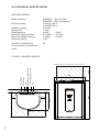
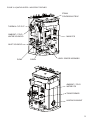
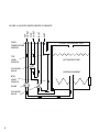
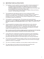
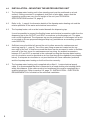
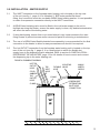
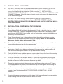
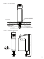
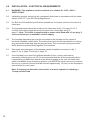
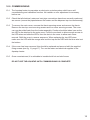
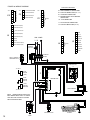
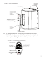
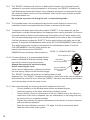
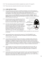
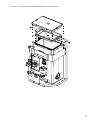
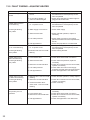
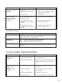
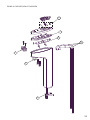
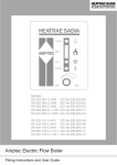
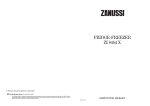
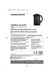
Aquatap (Boil and Chill / Boil and Ambient)
Installation and user manual
CONTENTS
SECTIONPAGE
1.0 INTRODUCTION3
2.0 TECHNICAL SPECIFICATION4
3.0 INSTALLATION - IMPORTANT INSTALLATION POINTS
7
4.0 INSTALLATION - MOUNTING THE WATER HEATING UNIT
8
5.0 INSTALLATION - WATER SUPPLY9
6.0 INSTALLATION - VENT PIPE10
7.0 INSTALLATION - DISPENSING TAP MOUNTING
10
8.0 INSTALLATION - DISPENSING TAP CONNECTION
12
9.0 INSTALLATION - ELECTRICAL REQUIREMENTS
14
10.0 COMMISSIONING15
11.0 USER INSTRUCTIONS19
12.0 MAINTENANCE20
13.0 FAULT FINDING22
14.0 SPARE PARTS24
15.0 GUARANTEE 30
16.0 ENVIRONMENTAL INFORMATION30
17.0 COMMISSIONING RECORD31
18.0 SERVICE RECORD32
19.0 SPARES STOCKISTS36
2
BOIL AND CHILL MODEL (INCLUDING BOIL AND AMBIENT)
1.0 INTRODUCTION
Thank you for purchasing a Heatrae Sadia Aquatap unit. This unit is manufactured to the highest
standards and has been designed to meet all the latest relevant constructional and safety specifications.
The Aquatap unit must be installed (see sections 3.0, page 7 to 9.0, page 14), commissioned (see
section 10.0, page 15) and maintained (see section 12.0, page 20) by a competent person. Please
read and understand these instructions prior to installing your Aquatap unit. Following installation
and commissioning of the unit, the operation of the Aquatap should be explained and demonstrated
to the user. Instructions for use are explained in section 11.0, page 19. These instructions should
be left with the user for future reference.
This appliance can be used by children aged from 8 years and above and persons
with reduced physical, sensory or mental capabilities, or lack of experience and
knowledge, if they have been given supervision or instruction concerning use of the
appliance in a safe way and understand the hazards involved. Children shall not play
with the appliance. Cleaning and user maintenance shall not be made by children
without supervision.
Intelliboil TMPlus is a patented control system for managing the efficiency of the Aquatap’s boiling cycle.
It regularly brings the contents of the water container to boil in response to ongoing user demand.
However, when there has been no draw off for a period of one hour, Intelliboil TMPlus steps back the
stored water temperature. This avoids unnecessary boiling - possibly for a number of hours or even
days - until there is renewed user demand. When this occurs, the boiling cycle resumes.
The appliance is intended to be used in commercial applications such as (but not limited to):
•
Hotel conference suites
•
Waiting rooms
•
Staff room kitchens/rest rooms
COMPONENT CHECKLIST
Before commencing installation, please check that all the following components have been supplied
in the packaging:
•
Aquatap dispensing tap (Boil and Chill/Ambient Model)
•
Aquatap water heating unit
•
Heatrae Sadia Superchill 30B (Boil and Chill Model)
•
3 x 0.5m hose
• 6 x hose clamps
•
10mm to 8mm elbow push fit adaptor (Boil & Chill only)
• 10mm to 6mm elbow push fit adaptor (Boil & Chill only)
• 6mm to 6mm stem elbow push fit adaptor (Boil & Chill only)
•
Tap C clamp box spanner
3
2.0 TECHNICAL SPECIFICATION
AQUATAP HEATER
Model reference
95200262 Boil and Chill
95200263
Boil and Ambient
Electrical rating
2.3kW @ 230 V ~
2.5kW @ 240 V ~
Nominal capacity
5.0 litres
Weight (full)17.5kg
Rated pressure
0 MPa
( 0 bar )
Minimum supply pressure
0.05 MPa ( 0.5 bar )
Maximum supply pressure
1.0 MPa
( 10 bar )
Enclosure ratingIPX2
Nominal commissioning time (minutes) to temperature
ready
24
FIGURE 1: AQUATAP HEATER
350mm
150mm
150mm
269mm
150mm
Minimum clearance needed around the heater unit
4
480mm
INLET
MAINS (ELECTRICAL SUPPLY)
HOT OUTLET
COLD OUTLET
TAP ELECTRICAL CONNECTION
VENT
150mm
Minimum clearance needed around the heater unit
FIGURE 2: AQUATAP HEATER - IMPORTANT FEATURES
STEAM
CONDENSING TRAP
THERMAL CUT-OUT
AMBIENT / COLD
WATER SOLENOID
MAIN PCB
INLET SOLENOID
PUMP
DRAIN
LEVEL SENSOR ASSEMBLY
AMBIENT / COLD
WATER PCB
TRANSFORMER
HEATING ELEMENT
5
OVER
TEMPERATURE
SENSOR
TOP
LEVEL
SENSOR
SOLENOID
VALVE
BTM
LEVEL
SENSOR
PUMP
SOLENOID
VALVE
6
VENT
INLET
HOT
OUTLET
COLD
OUTLET
FIGURE 3: AQUATAP WATER HEATER SCHEMATIC
STEAM CONDENSING TRAP
HOT WATER STORE
HEATING ELEMENT
3.0 IMPORTANT INSTALLATION POINTS
3.1 The Aquatap unit must be installed in accordance with the relevant requirements of:
•
The appropriate building regulations by application of either The Building Regulations (England and Wales), The Building Regulations (Scotland) or
The Building Regulations (Northern Ireland). In territories other than those listed
the local regulations in force must be complied with.
•
The Water Supply (Water Fittings) Regulations (England, Wales and Northern Ireland) or The Water Byelaws in Scotland.
3.2
The Aquatap stores and dispenses water at or close to boiling point whilst
switched on. Due caution must be taken when choosing a location for the product to
minimise any possible misuse. The dispenser tap should be located so that it
discharges over a sink or mounted on its own purpose designed drip tray (available as
an accessory, product code 95970138).
3.3 The Aquatap is a vented water heater. The vent pipe must never be blocked,
obstructed or removed. Warning: In the event of a unit malfunction, steam may vent
from the vent pipe for a short period of time (see fig. 5, page 11 for position of vent pipe).
3.4
Wherever possible the Aquatap should be supplied directly from the cold mains
supply. If fed from a cold water feed cistern, the cistern must comply with the
Water Regulations Guide (Clause R27.2). It should be noted that water quality may
be reduced when supplied from a cistern and additional pre-treatment of the water
supply to the Aquatap (eg, filtration) may be necessary.
Note: In order to meet the minimum supply pressure requirements of the Aquatap,
any cold feed cistern must be a minimum of 5 metres above the unit.
3.5 In hard water areas, heated water will produce limescale which will be deposited in
the heater. If this is not regularly removed it will impair the operation of the Aquatap
unit. Where rapid and excessive scale build up is likely to occur, the use of a
proprietary scale reducing device on the water supply to the unit may be beneficial.
3.6
The unit must not be installed where it is liable to freeze. If the unit is thought to be frozen it must not be switched on. It should be allowed to thaw and must then be thoroughly inspected to ensure it is undamaged.
3.7
The unit is not suitable for installation in an area where a water jet could be used.
3.8
The water chiller must be installed and commissioned in accordance with
SuperChill 30B Fitting Instructions and User Guide 36006126.
7
4.0
INSTALLATION – MOUNTING THE WATER HEATING UNIT
4.1
The Aquatap water heating unit is free standing and must be positioned on a level
surface. If being mounted in a cupboard, shelf unit or false base, ensure that the
supporting surface can carry the full weight of the unit (see TECHNICAL SPECIFICATIONS section 2.0, page 4)
4.2
Refer to fig. 1, page 4 for dimension details of the Aquatap water heating unit and the relative positions of the water and electrical connections.
4.3 The Aquatap heater unit must be located beneath the dispensing tap.
It must be possible to connect the flexible hoses and electrical connection cable from the
dispensing tap to the OUTLET and VENT connections on the Aquatap unit. The pipes
must not be lengthened. The dispenser tap can be positioned so it discharges into a sink or mounted on its own purposed designed drip tray (available as an accessory, product
code 95970138).
4.4
Sufficient room should be left around the unit to allow access for maintenance and
servicing (see fig. 1, page 4). Two of the case fixing screws are located on the top
rear edge of the unit; it must be ensured that these can be accessed in order to facilitate
removal of the front cover for maintenance and servicing. An ambient temperature between 5ºC and 35ºC is required in the cupboard housing the Aquatap water heating unit. Air circulation must be provided so air can flow through the cupboard (see diagram below). If adequate air circulation is not provided this will cause calibration problems and the Aquatap water heating unit will not function correctly.
4.5
The Aquatap water heating unit is supplied with a fitted 1.1 metre electrical supply
cable. It is recommended that this is connected to a fused double pole isolating switch
within this distance. If the cable needs to be lengthened this must be completed by a qualified electrician. Refer to section 9.0, page 14 - INSTALLATION – ELECTRICAL
REQUIREMENTS for full details of the electrical installation.
8
5.0 INSTALLATION - WATER SUPPLY
5.1
The INLET connection to the Aquatap water heating unit is located on the top rear
of the unit (see fig. 1, page 4). It is threaded ½” BSP male parallel flat faced
fitting. Any connection must use a suitable WRAS listed sealing washer. It is not possible
to make a compression connection directly to the INLET connection.
5.2 A WRAS listed isolating valve must be fitted in the cold water supply to the unit to
facilitate servicing the heater, ensure the water supply is clean, any debris/contamination will effect the taste of the boiling water.
5.3
If using hard piping, ensure this is not routed where it may impair access to the case fixing screws or prevent access and/or removal of parts for servicing or maintenance.
5.4
The use of a WRAS listed flexible braided hose assembly is recommended for the final
connection to the heater to allow for easy access/removal should it be required.
5.5
The hot OUTLET connection from the Aquatap water heating unit is located on the top
rear of the unit (see fig. 1, page 4). It is a hose spigot to which the flexible hot
supply hose to the dispensing tap is attached. Refer to section 8.0 INSTALLATION –
DISPENSING TAP MOUNTING, page 12 for full details of how to mount and connect
the dispensing tap to the water heating unit.
FIGURE 4: PLUMBING DIAGRAM
HOT TAP
OUTLET
HOSE
COLD /
AMBIENT
TAP
OUTLET
HOSE
CLAMP
TAP
VENT
HOSE
ISOLATING
FLEXIBLE VALVE
HOSE
MAINS
WATER
SUPPLY
CLAMP
SCREEN VENT
FILTER WITHIN
INLET HOSE
CONNECTION
9
6.0 INSTALLATION – VENT PIPE
6.1
The VENT connection from the Aquatap water heating unit is located on the top rear
of the unit (see fig. 1, page 4). It is a hose spigot to which the flexible VENT
hose of the dispensing tap is attached. Refer to section 7.0 INSTALLATION –
DISPENSING TAP MOUNTING below & section 8.0 INSTALLATION - DISPENSING TAP
CONNECTION, page 12 for full details of how to mount and connect the dispensing tap to the water heating unit.
6.2
The VENT will ensure that any excess steam or pressure is safely vented to
atmosphere in the event of a fault with the unit. IT MUST NOT BE BLOCKED,
OBSTRUCTED, DISCONNECTED OR REMOVED AND MUST BE VERTICAL WITH A CONTINUOUS RISE.
7.0 INSTALLATION – DISPENSING TAP MOUNTING
7.1
The dispensing tap supplied is suitable for mounting onto a worktop or counter surface.
It should be positioned such that it discharges into a sink or drip tray (see fig. 6, page 11 for tap dimensions). A purpose designed drip tray is available as an accessory (order product code 95970138). If this is used, then the instructions supplied with the drip tray
accessory should be followed.
7.2
Cut a 35mm diameter hole in the position selected through the worktop or counter
surface or use the template provided if using the drip tray. Note: Do not mount the
dispenser directly onto a stainless steel sink.
7.3
Screw the 6mm x 60mm stud into the base of the dispensing tap and connect the flexible hoses to the dispenser tap with the clips provided.
7.4
Ensure the sealing washer provided is correctly located on the base of the tap. A light
application of clear silicon sealant on the base of the tap and the sealing washer will
help ensure a watertight fit between the tap base and the worktop.
7.5
Feed the flexible hoses and the dispenser control cable through the hole in the worktop
from the top and position the tap base onto the worktop.
7.6
From the underside of the worktop fit the “C” clamp over the threaded securing post
and slide up so it sits against the underside of the worktop. The “arms” of the “C” clamp should enclose the flexible hoses and dispenser tap cable.
7.7 Thread the securing nut onto the securing post and finger tighten onto the “C” clamp.
If necessary adjust the position of the dispenser tap and then tighten the securing nut using the box spanner provided.
10
7.8
Make sure all pipe work is bonded and the earthing clamps conform to BS 951 and
contain a label which states “SAFETY ELECTRICAL CONNECTION - DO NOT
REMOVE”.
7.9
If required because of space issues cut the pipes (at the base of the tap) to an apropriate length making sure that they are free from burrs and clean.
FIGURE 5 : TAP MOUNTING
SEALING WASHER
WORK TOP
“C” CLAMP
SECURING NUT
COLD/AMBIENT PIPE
35mm HOLE
HOT PIPE
VENT PIPE
FIGURE 6 : DISPENSER DIMENSIONS
60.0
61.0
235
181
3mm
309
55 MAX
11
8.0 INSTALLATION – DISPENSING TAP CONNECTION
8.1 The hot supply hose should be connected to the OUTLET hose spigot of the Aquatap
water heating unit. The hose should rise continuously from the heater to the tap without kinks or twists. If necessary it can be cut to a shorter length, but it should never be lengthened. The hose should be secured in place on the spigot using the clamp provided.
Warning: Only use the hose supplied with the unit or a WRAS approved hose. Spare hose and clips can be ordered, product code 95607364.
8.2 The VENT hose should be connected to the VENT hose spigot of the Aquatap water
heating unit. The hose should rise continuously (vertical) from the heater to the tap without kinks or twists. If necessary it can be cut to a shorter length, but it should
never be lengthened.The hose should be secured in place on the spigot using the clamp provided.
8.3 The Ambient hose should be connected to the cold hose spigot of the Aquatap water
heating unit. The hose should rise continuously from the heater to the tap without kinks or twists. If necessary it can be cut to a shorter length, but it should never
be lengthened. The hose should be secured in place on the spigot using the clamp
provided.
FIGURE 7: TAP MOUNTING (BOIL & AMBIENT)
(NOTE: DRIP TRAY/SINK NOT SHOWN FOR CLARITY)
DISTANCE BETWEEN TAP AND HEATER
AS SHORT AS POSSIBLE TO ENSURE
CONNECTING PIPES RISE CONTINUOUSLY
DISPENSER CABLE
FUSED SPUR
CLAMP
WHITE HOSE
HOT TAP
OUTLET
HOSE
TAP
VENT
HOSE
1.5mm² 3 CORE HOFR
SHEATHED CABLE
COLD WATER
SUPPLY
CONNECTOR
AMBIENT
OUTLET
HOSE
CLAMP
FLEXIBLE
HOSE
2.5 BAR
PRESSURE REGULATOR
NOT SUPPLIED
(FIT ONLY IF REQUIRED)
12
8.4
Plug the dispensing tap cable connector into the Aquatap heater.
8.5 Wire up the Aquatap to a fused spur.
8.6
If a chiller unit is fitted to the dispenser, site the chiller near to the Aquatap heater, make sure that the chiller level tube is facing outwards to allow servicing.
8.7
Connect the water supply to the chiller as per fig 8. The chilled water supply via a
6mm pipe from the chiller should be connected to the “cold outlet” side of the Aquatap, a 6mm to 10mm John Guest fitting is supplied for ease of use.
8.8
The dispenser tap chilled hose should be connected to the “outlet” pipe of the chiller unit
The dispenser tap ambient hose should be connected to the “outlet” of the Aquatap and
secured in place with the pipe clamps supplied.
FIGURE 8: TAP MOUNTING (BOIL & CHILL)
(NOTE: DRIP TRAY/SINK NOT SHOWN FOR CLARITY)
DISTANCE BETWEEN TAP AND HEATER
AS SHORT AS POSSIBLE TO ENSURE
CONNECTING PIPES RISE CONTIUOUSLY
FUSED SPUR
DISPENSER CABLE
CLAMP
WHITE HOSE
HOT TAP
OUTLET
HOSE
COLD TAP
OUTLET
HOSE 6mm
+ INSULATION
1.5mm² 3 CORE
SHEATHED CABLE
TAP
CONNECTOR
TAP
VENT
HOSE
2.5 BAR
PRESSURE REGULATOR
NOT SUPPLIED
(FIT ONLY IF REQUIRED)
CHILLED WATER
SUPPLY
CLAMP
FLEXIBLE
HOSE
ISOLATING
VALVE
MAINS
WATER
SUPPLY
TEMP
SET
CHILLER
UNIT
POWER
SWITCH
ICE BANK
LEVEL
INDICATOR
WATER IN
8mm PIPE
150mm
MINIMUM DISTANCE
BETWEEN UNITS
13
9.0 INSTALLATION – ELECTRICAL REQUIREMENTS
14
9.1
WARNING: This appliance must be earthed. It is suitable for a 230 / 240 V ~
SUPPLY ONLY.
9.2
Installation must be carried out by a competent electrician in accordance with the latest
edition of BS 7671 (the IEE Wiring Regulations).
9.3
For Boil and Chill and Boil and Ambient installations, the heater unit must be wired to a fused spur.
9.4
The Aquatap heater should be wired into the fused spur as fig. 7/8, page 12/13. If
a chiller is also being used this should be wired into a fused spur as fig. 8,
page 13. Note: The chiller is supplied with a power cable fitted with a 3 pin plug. If
a second fused spur is available, use this supply.
9.5 The Aquatap dispensing tap must be connected to the Aquatap unit by means of
the black sheathed control cable. The cables from each unit are terminated in a mating
plug and socket rotate and align the plug correctly. This connects the plug and socket
which should be pushed firmly together for connection.
9.6
Schematic wiring diagrams of the Aquatap variant installation are shown in fig. 7, page 12, fig. 8, page 13 and fig.10, page 16.
9.7
If the Aquatap is not used for significant periods of time, running costs can be
reduced by switching the unit off. It is recommended that this is done automatically by
incorporating a suitable time switch in the electrical supply to the unit. A suitable time
switch is available as an accessory (product code 95970124) which can be set to switch the unit on, a period of time should be allowed (approximatly 1/2 hour) for the Aquatap to reheat before it is next used.
Note: If selecting an alternative time switch, it must be capable of switching a
13 amp resistive load.
10.0COMMISSIONING
10.1 The Aquatap heater incorporates an electronic controls system which has a self
commissioning and calibration function. No installer or user adjustment is necessary
before use.
10.2 Check that all electrical, water and vent pipe connections have been correctly made and
are secure (ensure the pipes between the heater and the dispense tap rise continuously).
10.3
To remove the main cover, unscrew the fascia securing screw and remove the fascia. Remove the two top cover securing screws and four cover securing screws. The cover can now be pulled back from the heater assembly. Caution should be taken here as the two LED’s are attached to the main cover. Pull the cover back to allow enough access to the LED wires and slide the LED’s from the slots in the cover to allow main cover removal. Refit the cover in reverse sequence. When replacing the two LED wires make sure the LED with the orange wire is at the top and the LED with the blue wire is at the bottom.
10.4 If the cover has been removed, this should be replaced and secured with the supplied
fixing screws (see fig. 11, page 17). Turn on the water and electrical supplies to the
Aquatap heater.
10.5 Once commissioned, it is advisable to insulate both hot and cold hoses.
DO NOT USE THE AQUATAP UNTIL COMMISSIONING IS COMPLETE
15
- SPARE
- SPARE
- LEVEL SENSOR (BTM)
- LEVEL SENSOR (TOP)
8
7
P3 - LED WIRING CONNECTOR
J5 - TEMPERATURE & LEVEL CONTROL
CONNECTOR
J13 - LINK CONNECTOR
5
- BLACK
4
P2
3
- THERMISTOR (TOP)
P2 - PCB LINK CONNECTIONS (P2 - J4 )
J3 - TAP DISPENSER CONNECTOR
2
- THERMISTOR (BTM)
P1 - TRANSFORMER 9v CONNECTION
J4 - PCB LINK CONNECTOR (J4 - P2)
1
}
TOP
6
4
3
8
2
9
- THERMISTOR (TOP)
7
1
1
2
3
4
5
- BLACK
- WHITE
- PURPLE
- BROWN
10 9
2
1
- ORANGE
- GREY
TERMINAL
BLOCK
3.15 A
1A
COLD / AMBIENT
SOLENOID VALVE
- YELLOW
- BLACK
3
THERMAL
CUT-OUT
5
J4
J3
- GREEN
6
6
L N
- BLUE
7
7
230 - 240V~
- RED
8
8
- ANTI-SCALE LOOP
4
6
10
- THERMISTOR (BTM)
6
- READY LED BLUE
5
- READY LED BLACK
4
- POWER LED BLACK
3
P3
PCB PLUG FUNCTIONS
- POWER LED ORANGE
2
J5
TOP
1
1
2
3
J13
4
5
TOP
LINK BETWEEN PINS 1 & 6
FIGURE 10: WIRING DIAGRAM
COLD / AMBIENT
CONTROL PCB
J3
J5 - PIN 1
Red
LEVEL
SENSOR
(TOP)
Black
J13 P3
10 6 4 3 12 9 2 1
LEVEL
SENSOR
(BOTTOM)
J5 - PIN 2
J4
J5
P1
LEVEL
SENSOR
(EARTH)
P2
CONTROL PCB
230V
J
TRANSFORMER
NOTE: SOME INTERNAL EARTH LINKS
NOT SHOWN FOR CLARITY. ALL EARTH
LINKS MUST BE SECURELY FASTENED
TO AN EARTHING POINT
SOLENOID VALVE
16
PUMP
ELEMENT
0 9V
TOP COVER
SECURING
SCREWS
FIGURE 11 : FRONT COVER REMOVAL
MAIN COVER
HOOK TOP EDGE
OF FASCIA INTO
COVER
APERTURE
ORANGE LED (TOP)
BLUE LED (BOTTOM)
FASCIA
SECURING
SCREW
COVER
SECURING SCREWS
10.6
The “TEMPERATURE READY” indicator light on the Aquatap heater unit and the
“READY” LED on the dispenser tap will flash. This indicates that the unit is in the self-
commissioning mode. Whilst in this mode, the water will not be hot enough for use. Do not draw any water off during the self - commissioning mode.
FIGURE 12 : LED POSITIONS (DISPENSER)
SAFETY BUTTON
HOT WATER
BUTTON
CHILLED/AMBIENT
WATER BUTTON
READY LED
BOILING WATER
LED
17
10.7 The “READY” indicators will continue to flash until the heater unit is full and has self calibrated to the correct boiling temperature. At this point, the “READY” indicators will stop flashing and remain illuminated. If the calibration procedure is interrupted the light will continue to flash until the unit has calibrated. Wait until the ready indicators remain illuminated before use. Do not draw any water off during the self - commissioning mode.
10.8 The Aquatap heater unit and dispenser tap should now be flushed to remove any installation residues and pasteurise the surfaces in contact with the water.
10.9
To dispense hot water press the button marked “SAFETY” on the dispenser tap (the safety button must be released before the dispense button can be activated. You have a 5 second window in which to start dispensing) followed by the HOT water button (red). The hot water dispensing button must remain pressed for the water to flow. If released,
it will be necessary to press the “SAFETY” button again before more water can be dis
pensed. To dispense chilled/ambient water, press the CHILLED/AMBIENT button (blue).
The safety button does not have to be pressed for chilled/ambient water. If both the CHILLED/AMBIENT and HOT water buttons are
pressed simultaneously the CHILLED/
FIGURE 13 : OPERATING BUTTONS
AMBIENT button will always take preference.
SAFETY BUTTON
10.10 Following flushing, it is recommended that the
power is switched off and the Aquatap casing
HOT WATER
DISPENSING
BUTTON
removed to check for any internal leaks.
Always disconnect the electrical supply
before removing the cover.
CHILLED/AMBIENT
WATER DISPENSING
If there are no leaks evident, replace and secure
BUTTON
the front casing. Switch on the electrical supply.
The “READY” indicator will illuminate on the Aquatap unit and
dispenser tap. The “READY” indicators will flash for a short time as the unit re-calibrates
and checks the correct fill level. When the “READY” indicators stop flashing and remain
solid, the Aquatap unit will be ready for use.
10.11 After commissioning, the following should be explained to the user:
•
Correct operation of the Aquatap water heater and dispensing tap.
•
Advise the position of the water and electrical isolation points.
•
How to identify if there is a malfunction of the unit. Explain that in the event of a
malfunction of the unit or dispenser tap, any maintenance or servicing must only be carried out by a competent installer.
•
Explain the necessity for regular maintenance of the system to ensure continued
safe and efficient operation.
•
Draw the users attention to section 11.0, page 19 of these instructions which
detail the correct use of the system.
18
10.12 The commisioning record should be completed (see section 15.0, page 31).
10.13 These instructions should be left with the user for future reference.
11.0 USER INSTRUCTIONS
11.1
Once installed and commissioned, the filling and heating cycles of the Aquatap are
completely automatic.The indicator lights on the dispensing tap will indicate the status
of the system. If the “READY” light is flashing this indicates that the unit is
self-calibrating. The Aquatap will enter this mode after any period of the electrical supply being switched off. DO NOT draw off water whilst the “READY” light is flashing. When the “READY” light stops flashing and remains illuminated, the unit will be ready to dispense boiling water.
FIGURE 14 : LED POSITIONS
11.2 Hot water drawn from the dispensing tap will at all
SAFETY BUTTON
times be close to boiling point so due caution must
be taken when using the product, especially if it is
HOT WATER
likely to be used by children, aged or infirm persons. DISPENSING BUTTON
11.3
Hot water cannot be dispensed unless the safety
CHILLED/AMBIENT
lock is turned off. The button marked “SAFETY”
WATER DISPENSING
should be pressed before the hot water dispensing
BUTTON
button.The dispensing button must be held in the
READY LED
pressed position to continue dispensing. If it is
released, the “SAFETY” button must be pressed
BOILING WATER
LED
again before more hot water can be dispensed.
If either the HOT button or CHILLED/AMBIENT button is pressed, the other button will not activate.
11.4 Ambient/chilled water is dispensed by pressing the CHILLED/AMBIENT water
dispensing button. The safety button does not need to be pressed for dispensing chilled/ambient drinking water.
11.5 In the unlikely event that the full store of hot water is completely drawn off from the
Aquatap, the pump will stop and flow from the dispenser will be interrupted. Should this happen, the “READY” indicator will flash. After a few minutes, the unit will have
re-filled to a level where hot water can again be drawn off. This will be indicated by the “READY” indicator remaining lit. If air becomes captive in the pump, operate the dispense
sequence to remove the air trapped in the pump. It does not indicate a fault with the
heater.
11.6 If the Aquatap is not used for a few days, the stored water may become “stale”. In these instances it is advisable to draw off and discard the entire contents to flush through the “stale” water. This will ensure that freshly boiled water is available for dispensing.
11.7
Occasionally some scale residue may be drawn from the unit with the dispensed water
which could cause the water to appear “milky” for a short while. This is completely
harmless and will quickly clear if left to stand. Alternatively a few cups of water can be
dispensed and discarded until the water flows clearly.
19
Normal Operation
Indication
Description
Boiling water light (dispenser)
Steady - when dispensing water
Ready light (dispenser)
Flashing - unit commissioning
Steady - normal operation
Off - unit too cold
wait
use
wait
Power light (heater)
Steady - normal operation
use
Ready light (heater)
Flashing - unit commissioning
Steady - normal operation
Off - unit too cold
wait
use
wait
PCB LED’s
Operating
Indication
LED 1 - Water level - Off indicates empty / below L0
Flashing indicates level between L1 and L2
On steady indicates full / level L2
LED 2 - Solenoid operating
LED 3 - Heating elements operating
LED 4 - Thermistor fault
12.0MAINTENANCE
Note: Any maintenance on the Aquatap water heater, dispensing tap or SuperChill 30B
must be carried out by competent persons. A competent person will be trained, experienced and qualified to work with this type of appliance.
Always disconnect the electrical supply before removing the cover.
Any water contained in the water heater may be very hot. Exercise caution when
removing.
Warning: The electronics control by switching the neutral (N). In some
instances, neutral terminations will be at 230 - 240V~ with respect to earth.
12.1 The Aquatap incorporates an electronic scale conditioning function which will reduce the
rate of scale deposition in hard water areas. However, some deposits may still occur in
the storage tank; these should be periodically removed.
12.2
The amount of usage of the unit will also determine the quantity of scale build up. A
regular inspection of the tank every 6 to 12 months will provide longer life of the product
and optimum performance (removal of the steam plate assembly will give access to the
storage tank).
12.3 Periodic cleaning of the screen vent filter within the inlet pipe will prevent debris collecting which could result in reduced performance.
20
FIGURE 15: EXPLODED VIEW FOR STEAM TRAP REMOVAL AND DESCALING
21
13.0 FAULT FINDING - AQUATAP HEATER
SYMPTOM
POSSIBLE CAUSE
No Indicator lights on
heater
1. If no water or heat - no power 1. Check power supply is correctly connected
to unit
and switched on. Check primary cut-out
has not operated
2. if hot water available - no
2. Check wiring harness to indicator lights is
power to indicators lights
plugged into control PCB
Heater does not fill on
commissioning
1. If POWER on indicator is not
lit - no power to unit
1. Check power supply is correctly connected
and switched on. Check primary cut-out
has not operated
Power light flashing
two pulses
2. Water supply not turned on
2. Check water supply
3. Solenoid valve fault
3. Check solenoid operation, replace if
necessary
4. Low water pressure
4. Check water is turned on and supply
pressure exceeds minimum requirements,
0.5 bar
5. Check inlet pipe filter is not obstructed
5. Inlet pipe blocked
Heater does not heat
up on commissioning
1. If POWER on indicator is not
lit - no power to unit
Power light flashing
three pulses
2. Element fault LED 3 on PCB
flashing
Heater does not fill
after commissioning
Power light flashing
two pulses
1. Level sensor fault
1. Check level sensor earth connection
2. Solenoid valve fault
2. Check solenoid operation, replace if
necessary
3. Check all connections to the control PCB,
replace if necessary
4. Check water is turned on and supply
pressure exceeds minimum requirements
5. Check inlet pipe filter is not obstructed
3. Electronic control PCB fault
4. Low water pressure
5. Inlet pipe blocked
1. Check power supply is correctly connected
and switched on. Check primary cut-out
has not operated
2. Check heating element
Heater does not heat
up after commisioning
Power light flashing
three pulses
1. Element fault - LED 3 on PCB 1. Check element operation, if faulty replace
flashing
2. Electronic control PCB fault
2. Check all connections to the control PCB,
replace if necessary
3. Control thermistor fault 3. Check continuity
short circuit - LED 4 on PCB
flashing
Water flow from vent
and primary cut-out
operates
1. Solenoid valve fault
2. Level sensor fault
3. Electronics control PCB fault
4. Inlet pipe blocked
22
ACTION
1. Check solenoid operations, replace if
necessary
2. Check level sensor earth connection
3. Check all connections to the control PCB,
replace if necessary
4. Check inlet pipe filter is not obstructed
SYMPTOM
Steam from vent pipe
and primary cut-out
operates
POSSIBLE CAUSE
1. Control thermistor fault
open circuit
2. Electronic control PCB fault
ACTION
1. Check continuity
2. Check all connections to the control
PCB, replace if necessary
3. Descale unit
3. Scale build up
Water consistently
cooler than when new
Power light flashing
one pulse
1. Control thermistor pocket has a
covering of scale
1. Descale unit, clean pocket surface
2. Control thermistor out of
calibration - LED 4 on PCB
flashing
2. Check thermistor values (5kΩ
at 100°C, 100kΩ at 25°C)
3. Steam thermistor out of
calibration - LED 4 on PCB
flashing
3. Check thermistor values (5kΩ
at 100°C, 100kΩ at 25°C)
Fault Diagnostic indicatiom
Indication
Description
Power light
Flashing one pulse - clean / de-scale, continue to use
Flashing two pulses - no water, also check solenoid
Flashing three pulses - Fault, see below
PCB LED’s
Fault Indications
LED 1 - Flashing indicates either Level sensor fault
LED 3 - Flashing indicates Heating element fault
LED 4 - Flashing indicates either Thermistor fault
Note
A fault logged is displayed for 10 seconds after turned on and Main PCB is
activated
13.0 FAULT FINDING - AQUATAP DISPENSER
SYMPTOM
POSSIBLE CAUSE
ACTION
Indicator lights on
heater, but not on
dispenser
1. Dispensing tap control cable
not connected to heater
1. Check that dispensing tap control cable is
connected to heater
2. Dispensing tap PCB fault
2. If tap control is correctly connected, check
and if necessary replace dispensing tap
PCB
No water flow when
dispenser button
pressed
Power light flashing
two pulses
1. Solenoid valve fault
1. Check solenoid operation, replace if
necessary
2. Pump not operating
2. Check supply to pump. If necessary
replace pump
3. Dispensing tap PCB fault
3. Check tap control cable
4. Inlet pipe blocked
4. Check inlet pipe filter is not obstructed
23
14.0 SPARE PARTS
DISPENSER ASSEMBLY
1
Top of dispenser kit95 607 377
2
Dispensing tap circuit board and harness
95 615 071
3
Pipe kit (3 pipes)95 607 379
4
Dispensing tap “C” clamp assembly
95 607 382
5
Tube spanner (not shown)95 607 384
6
Drip tray mesh (not shown)
95 607 694
HEATER ASSEMBLY
9
Thermistor control/steam95 612 696
10
Hose clip kit95 607 361
11
Vent pipe manifold95 607 370
12
Hose long95 607 371
13
Primary cutout (mounted on internal vent pipe)
95 612 001
14
Pump assembly95 607 372
15
Level sensor assembly 95 615 072
16
Hose short95 607 373
17
Inlet pipe assembly95 607 374
18
Solenoid valve assembly95 607 359
20
Manifold assembly solenoid to tank
95 615 073
21
Washer95 607 735
22
Control circuit board95 615 066
23
Steam condenser assembly 95 607 016
24
Transformer95 607 376
25
Condenser sealing gasket 95 611 819
26
O ring kit95 611 002
27
Tank 95 608 927
28
Element assembly 2.5kW (incorporating start dry cutout)
95 606 952
29
Element assembly sealing gasket
95 611 816
30
Adaptor nut, tube & washer kit
95 607 333
31
Start dry cutout (element)95 612 691
32
Cover assembly and screws
95 614 129
33
Wiring harness complete (not shown)
95 612 054
34
Indicator light wiring harness (not shown)
95 612 055
35
Tap assembly complete (boil & chill/ambient)
95 607 363
36
Hose and clip assembly (boil and vent)
95 607 364
37
Heater unit complete95 607 329
45
Screen vent filter
95 607 719
46
Outlet pipe cold / ambient95 607 754
CONTROL HOUSING
38
Relay circuit board (control housing)
95 607 440
39
Solenoid valve kit (control housing)
95 607 441
40
5 port terminal block (control housing)
95 607 442
41
Pipe Kit (inlet & outlet)
95 607 443
42
Hose, control to dispenser95 607 383
43
Control box assy complete95 607 389
44
Control box adaptor kit 8mm push fit - ½” BSPM
95 607 695
24
FIGURE 16: EXPLODED VIEW OF DISPENSER
1
1
2
13
1
1
4
25
FIGURE 17: EXPLODED VIEW HEATER ASSEMBLY
11
10
13
12
15
14
16
46
45
17
21
18
21
18
21
20
26
FIGURE 18: EXPLODED VIEW HEATER ASSEMBLY
9
22
38
24
23
25
26
25
27
27
FIGURE 19 : EXPLODED VIEW HEATER
28
9
30
28
29
31
FIGURE 20 : EXPLODED VIEW HEATER
32
29
GUARANTEE
This Aquatap water heater and dispensing tap assembly is guaranteed for a period of two years
from the date of purchase provided:
•
Both the Aquatap water heater unit and dispensing tap assembly have been installed
in accordance with these instructions and all necessary water, vent and electrical
connections have been fitted correctly.
•
Any valves or controls are of Heatrae Sadia recommended type.
•
The unit has not been tampered with and has been regularly maintained as detailed in
the maintenance instructions.
•
Only a recommended Aquatap dispensing tap assembly has been used to deliver the
boiling water.
•
The unit has been used only for heating wholesome (potable) water.
The unit and dispensing tap assembly are not guaranteed against damage by frost or due to the
build up of scale. Please note that if heateam (Heatrae Sadia’s service division) personnel or
agents are requested to descale a unit, this work will be chargeable.
Guarantee valid for UK only.
This guarantee does not affect the statutory rights of the consumer.
The pace of product development is such that we reserve the right to change product
specifications without notice. We do however, strive to ensure that all information in this leaflet is
accurate at the time of publication.
ENVIRONMENTAL INFORMATION
This product is manufactured from many recyclable materials. At the end of its useful life it
should be disposed of at a Local Authority Recycling Centre. Do not dispose of the unit in the
general household waste
30
15.0 COMMISSIONING RECORD
Installation Date:____________________________________________
Model and Serial Number: __________________________________
Installer (Plumbing): ________________________________________
Contact Details: ____________________________________________
Competency Scheme & ID Number: _________________________
Installer (Electrical): ________________________________________
Contact Details: ____________________________________________
Competency Scheme & ID Number: _________________________
Comments: ________________________________________________
________________________________________________
________________________________________________
Mains supply pressure and flow rate
Isolation valve fitted
2.5bar pressure regulator (fitted if required)
Pipework checked for leaks
Pipework bonded
Electrical connections checked
Filtered Flow rate
Boiling Flow rate
Boiling Temperature
31
16.0 SERVICE RECORD
Service Date:_______________________________________________
Engineer: __________________________________________________
Contact Details: ____________________________________________
Competency Scheme & ID Number: _________________________
Comments: ________________________________________________
________________________________________________
________________________________________________
Actions Carried Out: _______________________________________
________________________________________
________________________________________
________________________________________
________________________________________
32
NOTES:
33
NOTES:
34
NOTES:
35
After Sales Service
T: 0844 871 1535 F: 0844 871 1528
E: [email protected]
www.heatraesadia.com
Heatrae Sadia, Hurricane Way, Norwich,
Norfolk, NR6 6EA, United Kingdom
SPARES STOCKISTS:
Advanced Water Company Ltd
Unit D5 Enterprise Way
Vale Park, Evesham
Worcs, WR11 1GS
T: 01386 760066
F: 01386 760077
Electric Water Heating Co
2 Horsecroft Place, Pinnacles,
Harlow, Essex, CM19 5BT
T: 0845 055 3811
E: [email protected]
SPD
Units 9 & 10 Hexagon Business Centre
Springfield Road, Hayes,
Middlesex, UB4 0TY
T: 020 8606 3567
Parts Center
T: 0845 270 9800
W: www.partscenter.co.uk
Newey & Eyre
Unit 3/4/5 Wassage Way
Hampton Lovett Industrial Estate
Droitwich, Worcestershire, WR9 0NX
T: 01905 791500
F: 01905 791501
UK Spares Ltd
Unit 1155, Aztec West,
Almondsbury, Bristol, BS32 4TF
T: 01454 620500
William Wilson Ltd
Unit 3A, 780 South Street,
Whiteinch, Glasgow, G14 0SY
T: 0141 434 1530
Alternatively contact your local supplying
merchant or wholesale branch.
36
36006131_issue_05