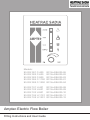
1
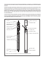
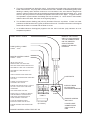
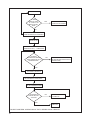
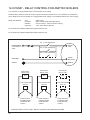
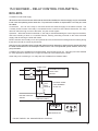
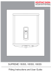
Models:
95 022 001 C-400
95 022 002 C-600
95 022 003 C-900
95 022 004 C-1100
95 022 005 C-1200
GC No.EB-205-06
GC No.EB-205-02
GC No.EB-205-03
GC No.EB-205-01
GC No.EB-205-04
95 022 101 U-401
95 022 102 U-601
95 022 103 U-901
95 022 104 U-1101
95 022 105 U-1201
GC No.EB-205-08
GC No.EB-205-09
GC No.EB-205-10
GC No.EB-205-11
GC No.EB-205-12
Amptec Electric Flow Boiler
Fitting Instructions and User Guide
1
THANK YOU FOR PURCHASING THIS HEATRAE SADIA AMPTEC FLOW BOILER. IT HAS BEEN DEVELOPED
TO PROVIDE YOU WITH MANY YEARS OF TROUBLE-FREE SERVICE WHEN INSTALLED IN THE PROPER
MANNER.
PLEASE READ AND UNDERSTAND THESE INSTRUCTION PRIOR TO INSTALLING YOUR HEATRAE SADIA
AMPTEC FLOW BOILER. THIS AMPTEC ELECTRIC BOILER MUST BE INSTALLED (SECTIONS 1.0 - 7.0),
COMMISSIONED (SECTION 8.0) AND MAINTAINED (SECTION 10.0) BY A COMPETENT PERSON ONLY.
PARTICULAR ATTENTION SHOULD BE PAID TO THE SECTION HEADED IMPORTANT INSTALLATION
POINTS. FOLLOWING INSTALLATION AND COMMISSIONING THE OPERATION OF THE BOILER SHOULD
BE EXPLAINED TO THE USER (SECTION 9.0) AND THESE INSTRUCTIONS LEFT WITH THEM FOR
FUTURE REFERENCE.
THIS APPLIANCE IS NOT INTENDED FOR USE BY PERSONS (INCLUDING CHILDREN) WITH REDUCED
PHYSICAL, SENSORY OR MENTAL CAPABILITIES, OR LACK OF EXPERIENCE AND KNOWLEDGE, UNLESS
THEY HAVE BEEN GIVEN SUPERVISION OR INSTRUCTION CONCERNING USE OF THE APPLIANCE BY
A PERSON RESPONSIBLE FOR THEIR SAFETY.
OUTLET
FRONT COVER (TOP)
RED IDENT
WARNING LABEL
ELECTRICAL CABLE
ENTRY POINTS
EARTH CLAMP
TERMINAL BLOCK
INSULATION SHEET
MAIN PCB
FLYING LEAD
CONTROL PANEL
FRONT COVER (BOTTOM)
BOILER ELEMENT
INSULATION
TEMPERATURE SWITCH
BLUE IDENT
INLET
RATING LABEL
SERIAL NUMBER
FIGURE ONE: MAIN COMPONENTS OF AMPTEC ELECTRIC FLOW BOILER
2
1.0 DESCRIPTION
The AMPTEC electric flow boiler is designed to heat re-circulated water used in wet central heating systems.
The water is heated when it is passed over electric immersion elements, which are contained in a chamber.
The temperature of the water is monitored and controlled by a modulation technique switching on the immersion
elements. The switching of the elements is carried out by solid-state technology contained in the control section
of the boiler. The operation of the boiler can be controlled by standard programmers, room thermostats, etc.
The pump should be connected to the boiler control, which provides the run-on facility.
2.0 FEATURES
·
·
·
·
·
·
·
·
·
·
·
·
·
·
·
Electric flow boiler for wet central heating systems.
Domestic hot water is available from a cylinder.
Can be used in a sealed or open vented system installations.
No flue or fuel tank required.
Quiet in operation.
Operates from standard programmers, room thermostats, etc.
Pump run-on facility.
Solid-state technology enables zero volt switching.
Soft start and soft modulation.
Front panel operation indicators.
User adjustment of the operating temperature on the front panel.
Self check every time it operates.
Optical isolation to enable connection of more boilers on single or three phase supplies.
Electrical tails terminations inside the boiler.
Safety trip for no water or no flow situations.
3.0 TECHNICAL SPECIFICATION
Output Temperature Control Range: (C series)
(U Series)
Operating voltage
Pump supply fuse (internal)
‘RUN’ control input signal requires ‘RUN’ control input signal draws less than 0.25A.
Optical isolation
Over temperature trips
Water content
650C to 800C.
300C to 600C
200V - 245V 50Hz
T 2A 240V - 20x5mm.
200V - 245V 50Hz
10mA typical.
Between the control signals
and the boiler supply.
95 and 1000C
1.3 litres
Product code Boiler type
220V / Btu
240V / Btu
Size
95 022 001
95 022 101
95 022 002
95 022 102
95 022 003
95 022 103
95 022 004
95 022 104
95 022 005
95 022 105
3.5kW / 11,900Btu
3.5kW / 11,900Btu
5kW / 17,000Btu
5kW / 17,000Btu
7.5kW / 25,600Btu
7.5kW / 25,600Btu
9kW / 30,700Btu
9kW / 30,700Btu
10kW / 34,000Btu
10kW / 34,000Btu
4kW / 13,600Btu
4kW / 13,600Btu
6kW / 20,400Btu
6kW / 20,400Btu
9kW / 30,700Btu
9kW / 30,700Btu
11kW / 37,500Btu
1kW / 37,500Btu
12kW / 40,900Btu
12kW / 40,900Btu
1050 x 90 x 90mm
1050 x 90 x 90mm
1050 x 90 x 90mm
1050 x 90 x 90mm
1050 x 90 x 90mm
1050 x 90 x 90mm
1050 x 90 x 90mm
1050 x 90 x 90mm
1050 x 90 x 90mm
1050 x 90 x 90mm
C400
U401
C600
U601
C900
U901
C1100
U1101
C1200
U1201
3
4.0 INSTALLATION - GENERAL
Care must be taken when handling and connecting the boiler not to damage or stress it in any way. Prior
to installation the boiler must be stored in a dry, safe place.
The boiler must be mounted in an upright position. The boiler must be fixed to a wall before connecting
pipework. When choosing the position for the boiler, ensure sufficient clearances to house the unit and for
servicing. 50mm minimum clearance each side of the boiler is required. A drain valve at the base of the
boiler is strongly recommended. It must be sited in a dry, ventilated position, frost free and not subjected
to extremes of temperature.
Note. Before connecting the pipework, ensure the rubber seal at the top of the boiler is firmly in place; check
it has not become loose in transit. The warranty will be invalid if water leaks into the boiler.
FLOW PIPEWORK
RED IDENT
30mm
20mm
5mm SECURING
HOLE
25.4mm
20mm
ENTRY PORTS
SUPPLY AND
CONTROL ON
BOTH SIDES
TOP HAUT ALTO OBEN
WARN ING
Before obtaining access to terminals all sup ply
circuits must be disconnected
Do not so lder directly onto flow and return p ipewor k
The guarantee will be withdrawn if this product is
ot ins talled in accordance with the installation
N
instructio
ns
30mm
Electroheat
65-80C
BAR M AX
-6KW
COPYRIGHT RE SE RVED PATENT APPLIED
FOR
Electroheat
Basings to ke UK RG24 9 RA
BOTTOM BA S BASSO U NTEN
RETURN PIPEWORK
FIGURE TWO: DIMENSIONS
4
900mm FIXING CENTRES
100mm
AMPTEC BOILER C600
GC NO. E B-205-02
OPERATING TEMPERATU RE
PRESSURE 3
220-240V ~ 5
BEAB CE N C CA
BACK VIEW
1050mm
90mm
FRONT VIEW
SIDE VIEW
AMPTEC
5.0 installation PLUMBING
The installation must be carried out in accordance with the relevant requirements of:
The appropriate Building Regulations, either The Building Regulations, The Building Regulations (Scotland)
or Building Regulations (Northern Ireland)
The Water Fittings Regulations or Water Byelaws in Scotland.
IT IS THE INSTALLER’S RESPONSIBILITY TO ENSURE THAT THE INSTALLATION DOES NOT CONTRAVENE THE REQUIREMENTS OF THE WATER SUPPLY REGULATIONS, BUILDING REGUALTIONS OR
LOCAL AUTHORITY REGULATIONS.
The boiler must be installed by a qualified, competent tradesman who is aware of and will comply with
all relevant standards that are applicable: e.g. Building Regulations, the Local Authority Regulations, the
Water Supply Regulations and undertaking the relevant British Standards. The system must be flushed in
accordance with BS 7593 and in accordance with the supplied instructions and drawings to ensure proper
operation.
The boilers contain a very small amount of water, and so require a sufficient flow rate of water to ensure
proper operation. Models 400 and 600 require a minimum flow of 6 litres/minute, and models 900, 1100
& 1200 require a minimum flow of 12 litres/minute. Insufficient flow of water through the boiler will cause
nuisance trip outs. The maximum temperature differential between input and output of the boiler must
not exceed 140C. If the temperature across the boiler exceeds this then the flow rate is too low and will
potentially damage the boiler. Set the flow rate to give 5 - 100C across the boiler on full heat.
The output flow pipe at the TOP of the boiler is identified red. The input return pipe is located at the
bottom. Ensure that the direction of flow is correct through the boiler after installation. Set the pump on
maximum flow rate.
Pipework connections on all models are 22mm.
Use standard size pipework. Do not solder directly onto the boiler tails. Push-on or
compression fittings are suitable for connecting directly onto the boiler tails. Fit a 22mm elbow to the top of
the boiler, and after 100 – 150mm of horizontal pipework fit an automatic air vent, or connect the expansion
pipework on open vented systems to provide a route for air to vent. DO NOT FIT THE AAV DIRECTLY
ABOVE THE BOILER.
The Amptec boiler is suitable for operation in sealed or open vented systems. It is also suitable for schemes
such as heating only, W plan, S plan, zone heating, under floor heating, micro-bore via a manifold, etc. If
you are unsure about your application regarding suitability of the boiler please do not hesitate to contact your
local supplier or Heatrae Sadia directly.
The cost of installation can be reduced if the electric flow boiler is used for heating only. Use a direct type
cylinder with immersion elements and a time clock for the domestic hot water, then connect the electric flow
boiler directly to the heating circuit and control it by a programmable room thermostat. If the radiator circuit
has a continuously open route for the water flow, then a bypass is not required. The boiler sizing is for
heating only in this case and does not have to be increased to allow for domestic hot water as well.
Ensure there is always an open route for the water to flow in any installation, to meet the required minimum
flow rate of the boilers and to allow for the pump over run. If an open route through the heating circuit can
not be guaranteed, then a bypass, fitted with an automatic bypass valve, must be fitted which meets the
required minimum flow rates for the boiler.
The bypass must have a minimum of either 2 metres of 22mm continuous pipework, or be routed through a
radiator with minimum dimensions of 600 x 600mm. Automatic pressure opening valves must be used with
the bypass circuit, ensure they are installed correctly as per the manufacturer’s instructions. Gate valves
are not suitable. DO NOT FIT A VALVE BETWEEN THE BOILER AND THE SAFETY PRESSURE RELIEF
VALVE OR EXPANSION RELIEF SYSTEM.
The boilers are suitable for operating pressures up to 3 bar. Normal sealed systems operate at 1 to 1.5 bar.
Ensure a safety pressure relief valve is fitted to all sealed systems. With open vented installations, ensure
there is a sufficient head of water for the pump to supply the full flow through the boiler of at least 1½ metres
between the bottom of the F & E tank and the top of the boiler.
5
NOTE: TO COMPLY WITH BUILDING REGULATIONS, PART L (PART J IN SCOTLAND), WHEN THE
AMPTEC IS USED FOR CENTRAL HEATING PURPOSES, A ROOM THERMOSTAT MUST BE FITTED TO
CONTROL THE BOILER (SEE PAGE 15).
Do not fit thermostatic radiator valves to the room with the control thermostat, other rooms may be fitted with
thermostatic radiator valves. DO NOT OPERATE UNDER THERMOSTATIC RADIATOR VALVES ONLY.
Use standard pumps, controls, room thermostat, valves, etc. The main electrical power (high current) must
be routed directly to the boiler via an MCB and RCD, not through the controls. Only a control signal to the
boiler comes from the programmer. The switching of the high power current is done inside the boiler.
For installations with more than one boiler, mount the boilers side-by-side with a minimum of 50mm gap
between each boiler, output flow tails at the top and the returns at the bottom. ‘Tee’ in the flows together,
increasing in pipe size at each boiler to ensure full flow to each boiler. E.g. for 3 x 1200 boilers, first boiler
use a 22mm elbow to the second boiler. Second boiler tee 22mm in from first boiler, 22mm branch to second
boiler, 28mm to third boiler. Third boiler tee 28mm in from second boiler, 22mm branch to third boiler, 35mm
away to heating circuit. Repeat for the return connections. Single pump in the 35mm flow line, ensure
sufficient flow for all 3 boilers, i.e. (for 3 x 1200 boilers requires 3 x 12 l/m = 36 litres/minute minimum). Do
not reduce pipework before ‘teeing’. See figure four on page 8.
When filling the system check for leaks. THE WARRANTY WILL BE INVALIDATED IF WATER LEAKS INTO
THE BOILER. ENSURE ALL JOINTS ABOVE THE BOILER ARE SOUND.
After installation the system must first be flushed out in accordance with BS 7593:1992 before adding the
inhibitor. Fernox “Superfloc”, or BetzDearborn Setinel X300 or X400 are ideal flushing agents for new
and existing systems. After flushing the correct amount of inhibitor must be added before use. Fernox
“Superconcentrate”, or MB-1, or BetzDearborn Sentinel X100 can be used for most water areas, however
we recommend you should check with your local water authority to ensure suitability. Check the inhibitor
concentration after installation and periodically thereafter to ensure correct protection.
FAILURE TO FLUSH PROPERLY OR INADEQUATE INHIBITOR IN THE SYSTEM WILL INVALIDATE THE
WARRANTY.
6
EXPANSION / SAFETY
RELIEF SYSTEM
AUTOMATIC AIR VENT
150mm MINIMUM
OPEN VENTED SYSTEMS MUST
HAVE A MINIMUM HEAD OF
1.5 METRES AND MAXIMUM
HEAD OF 30 METRES
PUMP
FLOW
2 METRES MINIMUM
AMPTEC BOILER
ISOLATING VALVE
AUTOMATIC
PRESSURE
BYPASS VALVE
RETURN
SERVICE VALVE
DRAIN VALVE
ALTERNATIVE BY-PASS ARRANGEMENT
USING THE BATHROOM RADIATOR FITTED
WITH TWO LOCKSHIELD VALVES
FIGURE THREE: BASIC PLUMBING LAYOUT
7
AUTOMATIC AIR VENT
22mm PIPE
FLOW
12 LITRE/
MIN
28mm PIPE
FLOW
24 LITRE/
MIN
EXPANSION / SAFETY
RELIEF SYSTEM
35mm PIPE
FLOW
36 LITRE/
MIN
PUMP
AMPTEC BOILER
AMPTEC BOILER
AMPTEC BOILER
RELAY
SYSTEM
95970136
SERVICE
VALVE
35mm PIPE
FLOW
RETURN 36 LITRE/
MIN
28mm PIPE
FLOW
24 LITRE/
MIN
22mm PIPE
FLOW
12 LITRE/
MIN
DRAIN VALVE
FIGURE FOUR: THREE BOILER PLUMBING SCHEMATIC
A typical plumbing schematic connecting 3 x 1200 boilers together.
NOTE the increase in pipework sizing to ensure proper flow through the boilers.
Ensure there are no restrictions in the heating circuit such as thermostatic radiator valves etc.
Expansion vessel etc. has not been shown on this schematic.
For 2 x 1200 boilers, 28mm pipework flow and return is required.
A bypass must be fitted. Preference should be made for a 600 x 600 radiator.
8
FLOW
6.0 installation - electrical requirements
all wiring must be carried out in accordance with CURRENT iee WIRING
regulations.
The AMPTEC boiler must be installed by a qualified competent tradesman in accordance with supplied
instructions and drawings to ensure correct operation.
Check the main incoming supply to the property to ensure there is sufficient current and voltage for the size
of the boiler or boilers to be installed. Remember to also take account of the supply requirements for the rest
of the property. Ensure the correct cable size is used to feed the boiler (refer to IEE wiring regulations).
A double pole RCD with a trip level sensitivity of 30mA and capable of breaking the full load current to BS
EN 61008:1994, must be used.
In order to provide a means of isolation, the boiler must be connected to the supply through a double pole
linked switch with a minimum contact gap of 3mm in all poles. The RCD is suitable for this requirement if it
is mounted in close proximity to the boiler.
A correctly rated MCB must be used in the supply, see Technical Specifications. An additional 3A supply is
required for the controls etc. NOTE, a blank must be fitted between each MCB to provide ventilation, check
with the MCB manufacture/supplier.
NOTE: The high current mains supply MUST NOT be routed through the programmer, controls etc. Follow
the wiring diagrams. Use a standard programmer, room thermostat, etc. The high current switching is
carried out inside the boiler, only standard switched live (low current) control signals are supplied by the
programmer etc.
Electrical Connections
Access can be gained to the electrical connections by removing the top front panel.
1 CONN5: MAIN POWER.Main power-supply cables. Connect the power cables from the power “supply”
(CONN5) terminals on the PCB assembly in the boiler directly to the isolation switch, live, neutral and
earth. Use the correct rated cable. Do not connect the power through the programmer, thermostats
etc. The main power PCB terminals in the boiler are suitable for cables up to 10mm2. NOTE: THESE
CONNECTIONS MUST BE TIGHT. LOOSE CONNECTIONS WILL CAUSE A FIRE. BURNING AT
CONN5 CONNECTOR IS NOT COVERED BY THE WARRANTY.
2 CONN1, pins 2 & 3: CONTROL SIGNAL.Connect switched live to ‘R’ and neutral to ‘N’ on the control
terminal block in the boiler to the switched live and neutral from the programmer control circuit. A neutral must be connected, as this control signal is optically isolated from the main supply in the boiler and will not run without a neutral. Do not connect any wires to the terminal marked N/C.
3 CONN1 pins 4, 5 &6:PUMP CONNECTIONS.The supply to the pump must be connected to the
‘PUMP’ terminal on the control terminal block in the boiler. This supply is fused in the boiler at 2A.
4. Cable access is made from either the right or left hand side via the X3 knockouts provided
(x1 25mm for power and x2 20mm for pump and thermostat cables). Having decided which side to
route the cabes, remove x3 knockouts only (This can be achieved with a small tap from a ball
nosed hammer, then twisting the knockout untill it is removed. Note: Take care not to damage the
casing, ensure the metal discs are retreived and no sharp edges are present. The cables should be installed using a suitable strain relief bush (not supplied).
X3 KNOCKOUTS
RIGHT HAND SIDE
X3 KNOCKOUTS
LEFT HAND SIDE
FIGURE FIVE:
FIGURE SIX:
9
Connections for 2 or more boilers.
1 CONN5: Main power-supply cables. Connect each boiler to its supply live, neutral, and earth, as
described above. The supplies to each boiler can be on different phases if using a 3-phase supply.
2 CONN1 pins 2 & 3: Control signal. Join all the boiler ‘R’ terminals on the control terminal block together, and then connect them to the switched live control signal to the programmer control
circuit. Connect all the boiler ‘N’ terminals on the control terminal block together and then to neutral
on the programmer control circuit.
3 CONN1: Pump connections. The pump must be connected through a relay assembly to ensure that the pump always operates if any one boiler is running. See page 26. Relay box 95970135 is required for a two boiler system and 95970136 is required for a 3 boiler system.
Check the main electrical power connections are tight. Support the back of the PCB behind the power
terminals when tightening the main power terminals. Loose connections can cause a fire and will invalidate
the warranty.
The control RUN signal is optically isolated from the main boiler supply to enable different phases to be
used between boilers. The control signal required to operate the boiler is 220V - 240V at a very low current,
typically 10mA.
Warning: this appliance must be earthed.
All exposed pipework must be earthed in accordance with IEE Regulations.
After installation, preliminary electrical checks i.e. short circuit, earth continuity, resistance to earth and
check for correct polarity etc. must be carried out.
Before connecting the electrical supply, ensure the system is full of water and set to the correct pressure
(sealed systems), check for leaks. It is essential that all the air is purged from the system. Only then can
the supply be switched on.
On completion of the work the installation must be tested to IEE Regulations and an NICEIC Inspection and
Completion Certificate must be issued.
Please take note of the installation information. If in doubt please contact your local supplier or Heatrae
Sadia.
CONN1
N
R
E
N
N
L
CONTROL
FIGURE SEVEN: BOILER INTERNAL SCHEMATIC
10
CONN5
E
ELEMENT
L
MAINS SUPPLY
N
BOILER SUPPLY
MCB
L
CONSUMER UNIT
AIR MCB
GAP
MCB MCB
DOUBLE POLE
RCD OR DOUBLE
POLE ISOLATION
3A FUSED
SPUR OR MCB
L
LOCAL TO BOILER
DOUBLE POLE
ISOLATION SWITCH
OR DOUBLE POLE
RCD
TO CONTROLS
PROGRAMMER / ETC
N
DEMAND SIGNAL
FROM CONTROLS/
PROGRAMMER ETC
(SEE TYPICAL
WIRING DIAGRAMS)
PUMP
N
R
E
N
HEAT RESISTANT
CABLE
L
N
CONN1
E
T
L
CONN5
AMPTEC BOILER
EARTH BONDING
TO BE PERFORMED
IN ACCORDANCE
WITH BS7671
FIGURE EIGHT: BOILER SUPPLY USING EXISTING CONSUMER UNI
11
MAINS SUPPLY CABLE
PUMP SUPPLY CABLE
0.5mm2 - 1mm2
BOILER CONTROL CABLE
0.5mm 2 - 1mm2
LIVE
EARTH
NEUTRAL
LIVE
NEUTRAL
EARTH
RUN
NEUTRAL
CASE EARTH
NO CONNECTION
CONTROL PUMP
NC N R E N L
NC N R E N L
CONTROL
PUMP
CONN 1
REMOVE TOP COVER ONLY TO
GAIN ACCESS TO THE
CONNECTIONS ON THE PRINTED
CIRCUIT BOARD INSIDE THE
BOILER HOUSING
FS 1 2A 240V
(5 X 20mm)
FIGURE NINE: BOILER WIRING DIAGRAM
12
N
L
SUPPORT BACK
OF PCB WHEN
TIGHTENING SCREWS
SUPPLY
CONN 5
ENSURE SCREWS
ARE TIGHT.
LOOSE CABLE
CONNECTIONS
CAN CAUSE A
FIRE
CYLINDER STAT
C 1 2
ROOM STAT
2 1 3
2 PORT VALVES
BLUE
GRN/YLW
BROWN
GREY
ORANGE
FROM 3A
FUSED SPUR
OR MCB
BLUE
GRN/YLW
BROWN
GREY
ORANGE
E
N
L
1
TO
BOILER
2
3
4
5
6
7
8
9
10
N
RUN
L
N
CH ON
HW ON
CH OFF
HW OFF
TIME CONTROLLER
FIGURE TEN: TYPICAL S PLAN WIRING DIAGRAM
13
MID POSITION
VALVE
CYLINDER
ROOM STAT
STAT
2 1 3
C 1 2
FROM 3A
FUSED SPUR
OR MCB
E
N
L
1
TO
BOILER
BLUE
G/YELLOW
BROWN
GREY
ORANGE
2
3
4
5
6
7
8
9
10
9
10
N
RUN
L
N
CH ON
HW ON
CH OFF
HW OFF
TIME CONTROLLER
FIGURE ELEVEN: TYPICAL Y PLAN WIRING DIAGRAM
PROGRAMMABLE ROOM
THERMOSTAT
A B C
FROM 3A
FUSED SPUR
OR MCB
E
N
L
1
TO
BOILER
2
3
4
5
N
RUN
FIGURE TWELVE: TYPICAL HEATING ONLY WIRING DIAGRAM
14
6
7
8
7.0 INSTALLATION - REVISED BUILDING REGULATIONS
Heating Controls To Comply With The Revised Building Regulations (Part L For England. Part J for
Scotland).
New Dwelling
1.
2.
3.
4.
5.
6.
7.
8.
9.
The installation must be a fully pumped system.
Independent temperature and time controls for both heating and domestic hot water.
Controls to interlock with the boiler. TRV’s alone do not comply.
An automatic bypass must be used if a bypass is required. Gate-valves do not comply.
Split heating circuits into zones: a. Room thermostat or programmable room thermostats in all zones.
b. A room thermostat or programmable room thermostats in the main zone and TRV’s in all other
zones.
Cylinder thermostat and zone valve to control stored hot water. Non-electric hot water controllers do not
comply.
Timed controller for heating and hot water must be provided.
A minimum of 2 zones for heating floor spaces greater than 150m2.
Boiler management control systems meeting specific zoning, timing and temperature requirements are
acceptable.
Existing Dwellings
When a new installation is fitted, the controls must be as for a new dwelling.
When replacing the boiler and/or hot water vessel, the opportunity to improve the controls should be considered
to be confident that the requirements of the Building Regulations are met.
15
8.0 COMMISSIONING
The boiler controls are fully automatic, making the operation very simple.
Only after the system has been flushed through and then filled with water, inhibitor and set to the correct pressure
(sealed systems), can the electrical supply be switched on.
Check 1.
When filling the system check for leaks. The warranty will be invalidated if water leaks into the
boiler. Ensure the joints above the boiler are sound.
Check 2. Before switching on the mains supply, check the main electrical power connections are tight.
Support the back of the PCB behind the power terminals when tightening the main power
terminals. Loose connections can cause a fire.
Initial set up procedure: 1. Ensure the main electrical supply and the programmer controls to the boiler are off and isolated.
2. Remove the pump live and neutral connection from the control terminal block in the boiler, and
reconnect the pump live wire into the control terminal ‘R’ together with the control signal wire. Connect
the pump neutral wire into the control terminal ‘N’ together with the control neutral wire.
3. Unplug the control block from the main PCB, ensure it is safe and not touching anything. The pump
is now fed from the control signal.
4. Check all air is purged from the system, and set the pump to maximum.
5. Switch on the control supply only (3 amp or 6 amp) MCB.
6. With the programmer and room thermostat on, check the pump is running and water is flowing.
Ensure the whole system, valves etc. are operating correctly. Continue to run the pump for some
time to purge any air. Don’t forget to bleed the pump.
7. Switch off the main supply RCD and MCB’s. Ensure it is all safe before reconnecting the pump
connections to the pump terminals as was originally wired. Reconnect the control terminal block
onto the PCB. Check all connections are made correctly, check the main supply terminals in the
boiler are tight, close and secure the top front cover of the boiler.
Main test procedure: Only after a satisfactory initial test, proceed as follows; 1. Switch on the main boiler MCB.
Switch on the programmer “control” (3 amp or 6 amp) MCB.
Switch on the RCD unit / Isolation switch.
Check the boiler front panel SUPPLY indicator is illuminated (green).
2. Set the programmer for central heating to ON.
Set the room thermostat to be ON.
The boiler front panel CALL indicator will flash (green).
This indicator will illuminate as a steady green after approximately 2-3 minutes.
Following the steady green, the HEAT indicator will build up gradually.
3. Check the temperature of the flow pipework from the boiler. This pipework should start to rise
in temperature. The rate of rise will depend upon the size of the boiler and system.
4. Check the full system operates correctly. If at any time the temperature difference between the
boiler return and flow is greater that 140C, then there is a flow restriction problem, and must be
rectified immediately. Set pump speed to give 5-100C differential between return and flow on the
boiler when operating at maximum power output.
16
5. The pump is operated from the boiler control. It should be connected to the pump terminals on the
boiler control board. The pump will run whenever the call indicator is illuminated (green) either
flashing or steady, and it will also continue to run if the boiler is hot, even after the demand has
ceased. It will turn off the pump when the boiler temperature falls below approximately 750C. It will
also turn the pump back on if the water temperature rises above 750C again. A bypass must be
incorporated in systems where the heating load can shut down, i.e. when valves or thermostatic
radiator valves are fitted. See note on the bypass (page 5).
6. The alarm indicator flashing (red) will only illuminate if there is a problem. If there is a water
problem the heat and the call (green) indicators will turn off. The boiler will remain in this tripped
state until the fault is corrected and the boiler is re-set.
7. An ALARM indicator flashing(red) together with the CALL indicator (red) indicates an over
temperature problem.
REMOVE TOP COVER
ONLY TO GAIN ACCESS
TO THE CONNECTIONS
ON THE PRINTED
CIRCUIT BOARD
INSIDE THE BOILER
HOUSING
MAINS SUPPLY CABLE
PUMP SUPPLY CABLE
2
2
0.5mm - 1mm
BOILER CONTROL CABLE
0.5mm2 - 1mm2
LIVE
EARTH
UNPLUG CONN1 BLOCK FROM PCB.
NEUTRAL
RECONNECT PUMP NEUTRAL TO
NEUTRAL.
LIVE
NEUTRAL
EARTH
RUN
NEUTRAL
RECONNECT PUMP LIVE TO RUN WIRE.
NO CONNECTION
INITIAL TEST SET UP
REMOVE PUMP LIVE AND PUMP
NEUTRAL WIRES FROM CONN1 BLOCK.
CASE EARTH
ENSURE IT IS SAFE BEFORE CARRYING
OUT TEST.
POWER UP SYSTEM WITH ALL
CONTROLS SET TO RUN.
ENSURE THE BOILER SUPPLY LIGHT IS
ON, CALL LIGHT IS OFF AND PUMP
IS RUNNING.
THIS COMPLETES THE TEST.
SWITCH OFF ALL POWER TO BOILER
AND RECONNECT PUMP NEUTRAL
AND PUMP LIVE WIRES BACK TO
THEIR ORIGINAL POSITIONS.
PLUG THE TERMINAL BLOCK
BACK INTO CONN1 ON THE PCB.
ENSURE CONNECTION SCREWS ARE
TIGHT
CONTROL PUMP
NC N R E N L
NC N R E N L
CONTROL
PUMP
CONN 1
FS 1 2A 240V
(5 X 20mm)
FIGURE THIRTEEN: INITIAL TEST SET UP
N
L
SUPPORT BACK
OF PCB WHEN
TIGHTENING SCREWS
SUPPLY
CONN 5
ENSURE SCREWS
ARE TIGHT.
LOOSE CABLE
CONNECTIONS
CAN CAUSE A
FIRE
17
MAIN POWER ON
IS TEMP
SWITCH OPEN
I.E. FAULTY OR
BOILER OVER
TEMP
YES
CALL LED RED
ALARM LED FLASHING
NO
CONTINUE CHECK FOR ALL AS
LONG AS BOILER IS POWERED
RUN TO ON
PUMP ON AND PRE-HEAT ON
THEN WAIT FOR 1 - 1.5 MINUTES
DO BOTH
THERMISTOR BEADS
READ SAME VALUE I.E.
TEMPERATURE
NO
ALARM LED FLASHING
(NO WATER OR INSUFFICIENT
WATER FLOW)
YES
CONTINUE CHECK FOR A
FURTHER 2 MINUTES
SWITCH OFF PRE-HEAT ,POWER
UP AND MODULATE BOILER
RUN TO OFF
BOILER POWERS DOWN
IS WATER IN
BOILER BELOW
70ºC/75ºC
NO
KEEP PUMP RUNNING
OR PUMP ON
YES
PUMP OFF
FIGURE FOURTEEN: OPERATION OF THE C SERIES ISSUE 5 BOILER
18
9.0 Operation and indicators
The Supply indicator (green) will remain illuminated all the time the supply is present to the boiler.
The Call indicator will illuminate (green) on demand from the programmer and thermostats or (red) for an
alarm overheat condition. It will flash (green) for 2 to 3 minutes during which it carries out self-tests before
allowing the boiler to produce heat. At the end of this period it will remain on steady (green), until the
heating demand is satisfied.
The heat indicator will illuminate when the boiler actually
produces heat, this is only when the CALL indicator (green)
is steady. The gradual build up in heating power of the boiler
can be seen on the front panel. The heat indicator also shows
the boiler modulating when it reaches operating temperature.
The alarm indicator flashing (red) will only illuminate if there is
a problem. The heat and the call (green) indicators will turn
off. The boiler will remain in this tripped state until it is re-set.
To reset an ALARM follow the ‘Alarm Reset’ procedure.
TEMPERATURE CONTROL. The boiler output temperature can
be adjusted from the front panel. Minimum setting for C series is
approximately 650C and U series 300C. Maximum setting for C
series is approximately 800C and U series is 600C.
CLEANING
Use only a damp cloth and mild detergent to clean the boiler outer
casing. Do not use abrasive cleaners. Do not allow water inside
the boiler. Do not immerse in water.
FIGURE FIFTEEN: CONTROL PANEL
10.0 Servicing
IT IS ESSENTIAL THAT THE BOILER IS CHECKED ANNUALLY, Checks must include the electrical
connections and inhibitor concentration.
Before any servicing or maintenance is carried out on the system, ensure that the electrical supply has been
disconnected first. Care must also be taken as the water may be scalding hot and at a high pressure.
Check the main electrical power connections are tight. Loose connections can cause a fire.
Part Locations and comments (see page 2)
Fuse FS1 is found near the top of the main power PCB assembly.
The temperature switch connected to Conn 3 is situated on the body of the boiler approximately 1/3rd of the
distance up from the bottom between insulation and boiler.
The thermistor assembly plugs into the main power PCB assembly through Conn 4, and is clamped at the
top of the boiler. Care must be taken not to break the fine wires.
The control PCB assembly is mounted on the back of the bottom front panel, and plugged into the main
power PCB Conn 2. Great care must be taken when changing this board assembly not to damage any of the
components, especially those adjacent to the mountings.
To change the main power PCB, follow ‘Replacing the Main Power PCB’ procedure (see page 20).
Each of the main electrical elements should have a resistance of approximately 19 ohms terminal to terminal,
(red to red, yellow to yellow, blue to blue and black to black) and an insulation resistance greater than 2 Meg
ohms between terminal and case. If the elements are open circuit terminal to terminal, or have short circuit
insulation resistance terminal to case, then the boiler must be replaced.
19
11.0 Replacing the Main Power PCB
Note. Before any maintenance is carried out on the system, ensure that the electrical supply has been
disconnected first. Care must be taken as the water may be scalding hot and at high pressure.
Maintenance on the boiler can only be carried out by a qualified and competent tradesman in accordance
with supplied instructions.
Removal of the Main Power PCB
1 Switch OFF electrical supplies to the boiler. Both Main, “Live and Neutral”, and Control “R and N” must be isolated
2 Remove the front top panel.
3 Disconnect the control PCB and carefully remove the high temperature insulation and the front bottom panel.
4 Unplug the control connector (Conn1), the temperature switch connector (Conn3), and the thermistor connector (Conn4).
5 Unplug the power connectors on the elements.
6 Disconnect the main power cable to Conn5.
7 Remove the 4 screws identified by the black triangles, see figure fourteen below.
8 Carefully remove the PCB assembly from the pipework. This may be stiff and gentle prising at the
top may be required.
Replacing the Main Power PCB
1 Ensure heat sink compound is used on the heat sinks.
2 Identify and plug the power connectors onto the elements, colour for colour, as it is easier to make these connections before fitting the PCB.
3 Holding the back plate line up the pillars with the PCB and position it onto the pipework.
4 Loosely add the 4 fixing screws.
5 Tighten up these screws in the order shown below in figure fourteen. It is important to ensure that the PCB assembly is tight on the pipework.
6 Reconnect the control PCB and replace the high temperature insulation.
7 Ensure the main power connections are tight. Loose connections can cause a fire.
2
1
3
4
FIGURE SIXTEEN: MAIN POWER PCB
20
12.0 FAULT FINDING
1 Should the alarm indicator illuminate ‘flashing’ (red) instantly on power up, then the connections ‘Conn 4’have become loose or disconnected in transit or if the ALARM indicator is ‘flashing’ (red) and the CALL indicator is (red), then ‘Conn 3’ or the thermostatic switch wires have become loose.
2 Should the alarm indicator illuminate ‘flashing’ (red) during the call checking period then there is a
problem due to lack of water or air in the system.
3 Should the ALARM indicator illuminate ‘flashing’ (red) and the CALL light show (red) after heat is applied then there is a problem due to lack of water flow. See Fault Finding chart.
NotE: It may be necessary to fit a capacitor between the ‘R’ run and ‘N’ neutral terminals on the control connector
to prevent the boiler continuing to run when the cylinder and the room thermostats are satisfied. This is due to
a leakage current from some manufacturers 3 port valves. The capacitor required is 0.47 micro-farads suitable
for 275 volts AC (X2 style). These capacitors are available from Heatrae Sadia 95 612 708.
13.0 ALARM RESET
There are 3 steps to re-set a tripped condition: 1
Switch “off” the electrical supply.
2
Correct the fault, check the system is full of water and set to the correct pressure (sealed systems) and
there is a good flow of water (i.e. all the valves are open).
3
Switch the supply back “on”.
Ensure the customer fully understands the operation of the system.
The Boiler must NOT be operated if it is known to have a fault. Switch off, and call a service engineer.
21
THE BOILER IS NOT
OPERATING
IS
THE SUPPLY LED
ILLUMINATED
PLEASE CHECK THE FOLLOWING
BEFORE GOING THROUGH THE
FAULT FINDING CHART:
CHECK INSTALLATION IS
CORRECT
ALL ISOLATING VALVES
ARE OPEN
THE PUMP IS RUNNING
GO TO SUPPLY LED OFF
FAULT FINDING SECTION
YES
GO TO ALARM
FAULT FINDING SECTION
NO
GOTO CALL LED
FA ULT FINDING SECTION
YES
IS THE
ALARM LED
ILLUMINATED
THE SYSTEM IS FULL OF WATER
(PRESSURISED) AND PURGED OF
AIR
THE PROGRAMMER AND
CONTROLS ARE ON
NO
NO
IS THE
CALL LED
FLASHING
THE ELECTRICAL SUPPLY IS
CONNECTED CORRECTLY
AND PRESENT
YES
DOES THE CALL
NO
LED GO SOLID AFTER
3 MINUTES
GO TO CALL LED
FAULT FINDING SECTION
YES
ARE THE
HEAT LEDS
ILLUMINATED
NO
CHECK WATER FLOW
YES
IS THE
TOP SW LED 3
ON THE MAIN PCB
ILLUMINATED
NO
CHANGE MAIN PCB
YES
CHECK ELEMENTS
FIGURE SEVENTEEN: FAULT FINDING CHART
22
SUPPLY LED OFF
IS THE
MAIN SUPPLY
AVAILABLE
NO
CHECK 240V IS SUPPLIED
TO THE MAIN POWER TERMINAL
CONN5
YES
IS THERE
230V ON TVR 1
MAIN PCB
NO
CHECK FOR SHORT CIRCUITS
ON WIRING TO THE PUMP.
IF OK REPLACE FS1 FUSE.
T 2A 240V 20 x 5mm
YES
IS THERE
8V DC ON
C1 MAIN PCB
NO
REPLACE THE MAIN POWER PCB
YES
REPLACE THE CONTROL PCB
FIGURE EIGHTEEN: SUPPLY LED OFF
ALARM TRIPS INSTANTLY ON POWER UP.
BOTH CALL AND ALARM LEDS ARE RED
IS THE
BOILER HOT
YES
IS THE
PUMP RUNNING
YES
RUN SYSTEM WITH ALARM TO
ALLOW PUMP TO COOL SYSTEM
BEFORE RESETING
YES
CHECK SERVICE VALVES ARE
FULLY OPEN.
CHECK AND REPLACE PUMP.
NO
NO
IS THE
PUMP NEON
ILLUMINATED
NO
CHANGE CONTROL PCB
IS CONN 3
OPEN CIRCUIT
YES
NO
FIGURE NINETEEN: ALARM ONE
CHECK AND REPLACE THE
TEMPERATURE SWITCH CONN 3
THERE IS NO WATER IN THE
SYSTEM. SWITCH OFF IMMEDIATELY.
CHECK AND REFILL BEFORE
RESTARTING.
23
ALARM TRIPS DURING
SELF CHECKING BUT NOT
INSTANTLY
THERE IS NO WATER IN THE SYSTEM.
SWITCH OFF IMMEDIATELY.
CHECK AND FILL BEFORE RESTARTING.
FIGURE TWENTY: ALARM TWO
ALARM TRIPS AFTER A
FEW MINUTES OF OPERATION
IS THE PUMP
RUNNING
YES
CHECK FOR A RESTRICTION IN THE FLOW.
CHECK THE BYPASS, CHECK THE SERVICE
AND RADIATOR VALVES.
CHECK FOR AIR IN THE SYSTEM.
NO
IS THE
PUMP NEON
ILLUMINATED
YES
NO
FIGURE TWENTY ONE: ALARM THREE
CHECK AND OPEN SERVICE VALVES.
CHECK AND REPLACE THE PUMP.
IF THE PUMP NEON ON THE PCB DOES NOT
ILLUMINATE WHEN THE CALL IS ILLUMINATED
REPLACE THE CONTROL PCB.
OCCASIONAL TRIPPING
TRIPPING
DAILY
YES
NO
FIGURE TWENTY TWO: ALARM FOUR
24
CHECK FLOW AND PRESSURE.
CHECK FOR TEMPORARY RESTRICTIONS IN FLOW.
CHECK CONNECTIONS ON THERMOSTATIC SWITCH
CONN3.
CHANGE CONTROL PCB.
CHECK FLOW AND PRESSURE.
CHECK FOR TEMPORARY RESTRICTIONS IN FLOW.
CHECK CONNECTIONS ON THERMOSTATIC SWITCH
CONN3.
RESET.
CALL LED NOT FLASHING
IS THE 230V
DEMAND AVAILABLE
NO
CHECK AND SET THE PROGRAMMER
AND THERMOSTATS ON
YES
IS THERE 230V
BETWEEN R AND N
CONTROL
NO
CHECK THE WIRING TO
THE BOILER
YES
IS NEUTRAL
CONNECTED TO
N CONTROL
NO
NEUTRAL MUST BE CONNECTED
TO N ON THE CONTROL CONNECTOR
YES
CHANGE THE CONTROL PCB
FIGURE TWENTY THREE: CALL LED NOT FLASHING
CALL LED NOT STEADY
AFTER 3 MINUTES
DOES THE MAIN
RCD TRIP
YES
NO
CHANGE CONTROL PCB
CHECK THE INSULATION ON THE ELEMENTS
FIGURE TWENTY FOUR: CALL LED NOT STEADY
25
14.0 PUMP - RELAY CONTROL FOR AMPTEC BOILERS
2 or 3 boilers on single phase 240V or three phase 415V supply
Isolation relays must be used as shown in figure twenty three below for 2 or more boilers to operate the
pump. Boilers can be connected on a single phase 240V supply or on separate phases of a 415V supply.
Relay specification: Coil Contacts Isolation Capacitor
240V 50 Hz
240V 10Amps N/O (Normally Open)
Coil to Contact - 415V minimum working.
4.7uF 240V 50Hz Class X2
For 2 boilers use Heatrae Sadia Part Number 95 970 135
For 3 boilers use Heatrae Sadia Part Number 95 970 136
RL 1 - N/O CONTACT
PERMANENT
LIVE SUPPLY
240V
PUMP
LIVE
RL 2 - N/O CONTACT
RL 3 - N/O CONTACT
NEUTRAL
PUMP
NEUTRAL
EARTH
EARTH
N
ISOLATION
RELAY COIL
ISOLATION
RELAY COIL
ISOLATION
RELAY COIL
RL1
RL2
RL3
240V
240V
240V
4.7uF CAPACITOR
240V AC
4.7uF CAPACITOR
240V AC
4.7uF CAPACITOR
240V AC
PUMP OUTPUT
CONNECTIONS
FROM BOILER
CONN 1
L
N
PUMP OUTPUT
CONNECTIONS
FROM BOILER
CONN 1
L
N
PUMP OUTPUT
CONNECTIONS
FROM BOILER
CONN 1
FIGURE TWENTY FIVE: PUMP - RELAY CONTROL FOR AMPTEC BOILERS
26
L
15.0 SHOWER – RELAY CONTROL FOR AMPTEC®
BOILERS.
Limitations on electrical supply
Where there is an electric shower and an electric flow boiler installed, the electrical supply may be overloaded
if both units are operating at the same time. To prevent this condition a simple switch over relay box must
be added.
Connections: - The coil of the relay is connected across the switched supply to the electric shower. The
‘normally closed’ contact of the relay is connected into the control line of the electric flow boiler. The relay
does not switch the high current to the boiler, only the control signals.
Operation: - When the shower is switched on, the relay is activated breaking the control signal to the boiler,
and hence shutting it down in a controlled manner, thereby preventing overload on the mains electrical
supply. After showering the boiler will restart.
Electric showers are normally run for short periods at a time, and therefore shutting down the heating during
these times should not cause any discomfort.
Note, this is only required if there is doubt with regard to supply limitations, and an electric shower that heats
the water at the same time as the Amptec boiler is used. It is not required with power showers, which only
pump the water.
A suitable relay unit is available from Heatrae Sadia. Part number 95 970 134. This relay unit is also suitable
for other applications where there is a high load demand to be shared with the boiler.
Other relay units containing 2 or 3 relays are also available from Heatrae Sadia.
2 AMP FUSE
SHOWER OR OTHER
HIGH LOAD
DEVICE
PULL SWITCH
A1
A2
HEATRAE SADIA
PART NUMBER
95 970 134
COIL
240V
50/60HZ
14
BOILER CONTROL
SIGNAL
11
12
NORMALLY CLOSED
CONTACT (240V)
-
NR
NL
N
AMPTEC BOILER
L
SUPPLY
FIGURE TWENTY SIX: SHOWER RELAY CONTROL
27
16.0 GUARANTEE.
This product is guaranteed against faulty materials and manufacture for a period of 2 years from the date of
purchase provided that:
1.
2.
3.
The unit has been installed in accordance with the Installation and User Instructions and all relevant Codes of Practice and Regulations in force at the time of Installation, and that all necessary controls and safety valves have been fitted correctly.
The unit has not been modified or tampered with in any way, and has been regularly maintained as detailed in the Installation and User Instructions.
The unit has been used only for domestic heating purposes.
The unit is not guaranteed against damage by frost, and the immersion heater is not guaranteed against
excessive scale build-up.
This Guarantee in no way affects the statuory rights of the consumer.
The policy of Heatrae Sadia is one of continuous product development and, as such, we reserve the right to
change specifications without notice.
17.0 ENVIRONMENTAL INFORMATION.
Heatrae Sadia products are manufactured from many recyclable materials.
At the end of their useful life they should be disposed of at a Local Authority Recycling Centre in order to
realise the full environmental benefits.
18.0 PARTS LIST
Part Number
Description
95615047
Main Power PCB Assembly
95615046
Control PCB Assembly
95612709
Fuse T 2A 240V
95613628
Temperature Switch + Cable Assembly
95612706
Thermistor Assembly
95612708
Capacitor 0.4uF
95614290
Front Top Cover Plate
19.0 Spares Stockists
Electric Water Heating Co. Newey & Eyre Specialists Products Division
Eyre & Elliston
UK Spares Ltd.
Heating Replacement Parts & Controls
William Wilson Ltd.
2 Horsecroft PLace, Pinnacles, Harlow, Essex, CM19 5BT.
Tel: 0845 0553811
E-mail: [email protected]
Unit 12, Spitfire Way, Airlinks Industrial Estate, Heston, Middlesex, TW5 9NR.
Tel: 020 8573 0574
PO Box 48, Tomlinson Road, Leyland, Preston, Lancashire, PR5 1JX.
Tel: 01772 819673
www.hrpc.co.uk
Hurricane Way, Norwich, NR6 6EA
www.heatraesadia.co.uk
Tel:
28 01603 420100
© 2008
Please contact your local branch
Tower Lane, Warmley, Bristol, BS30 8XT.
Tel: 0117 961 6670
94 Kinning Street, Glasgow, G5 8LW.
Tel: 0141 4201661
Customer Service
Tel: 0844 8711535
Fax: 0844 8711528
Email:[email protected]
36005871 issue 4