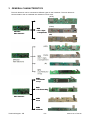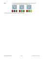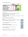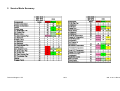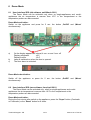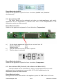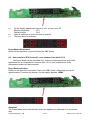
1
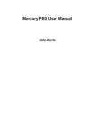
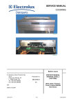
SERVICE MANUAL REFRIGERATION © ELECTROLUX HOME PRODUCTS Customer Care - EMEA Training and Operations Support Technical Support Publication number 599 73 16-11 EN Edition: 2011-05 - Rev. 02 ERF2001 ERF2530 TABLE OF CONTENTS 1 2 3 4 Purpose Precautions General characteristics Service Mode 4.1 Service Mode Activation 4.2 Component test 4.3 User Interface visual test 4.4 AC output test 4.5 Digital output test 4.6 Damper test 4.7 Digital input test 4.8 Temperature probe test 4.9 Software and Parameters 4.10 Life time display 4.11 Final phase Service Mode Summary Demo Mode 6.1 User Interface SRS (old software, until March 2011) 6.2 User Interface SRS (new software, from April 2011) 6.3 User Interface SHD 6.4 User Interface SLD 6.5 User Interface SPX (old software, until March 2011) 6.6 User Interface SPX (new software, from April 2011) 6.7 User Interface KNB 5 6 3 3 4 5 5 5 5 7 8 9 9 10 10 11 11 12 13 13 13 14 15 15 16 17 REVISIONS: Revision Date 00 06/2010 Document creation PR 01 09/2010 Added variants on “Service Mode” activation and Summary PR 02 05/2011 Document Updated; Demo Mode chapter added PR Technical Support - PR Description 2/17 Author Approved by - on 599 73 16-11 Rev.02 1 PURPOSE The purpose of this manual is to provide service personnel (who already have the basic knowledge necessary for repairing refrigerators and freezers) with information on appliances equipped with the ERF2001 or ERF2530 electronic control system. This Manual describes: • User Interfaces that could be connected with • Service Mode activation • Tests that could be processed 2 PRECAUTIONS Electrical appliances must be serviced only by qualified Service Engineers. Always remove the plug from the power socket before touching internal components. Technical Support - PR 3/17 599 73 16-11 Rev.02 3 GENERAL CHARACTERISTICS The main electronic can be connected to different types of user interfaces. The main electronic communicates to the not insulated user interfaces via six wires. (AEG) (Delta) ERF2001 Main electronic SRS LED + digits 1 compartment (Bi) SHD LCD ENV06 on top SLD LCD Smart-design ERF2001 Main electronic KNB Knob KNB MiniKnob Technical Support - PR 4/17 599 73 16-11 Rev.02 4 SERVICE MODE 4.1 Service Mode Activation The activation of the Service Mode is depends on the Software, which is loads on the electronic. There are two variants of activation in the Service Mode Variant 1: • Switch on the appliance • Open the door • Unplug the appliance • Plug in the appliance Variant 2: • Switch on the appliance Then valid for both: o After 6 sec. pressing any push button (from now on this button will be the „next“-key) except the On/Off-button for 5 sec. The push button must be pressed in the timeframe from 6 to 16 sec, otherwise the Service Mode is not activated. The Service Mode activation is confirmed by a short beep from the buzzer device. Each other push button will be the “action-key” when pressed after that. Definition of “next-key” and “action-key”: • the „next“-key can be any push button except the On/Off-button. With the „next“-key, you can activate the Service Mode and you can change in a new test-phase. • the „action“-key can be any push button except the „next“-key. With the „action“-key, you can switch on and off the components. 4.2 Component test The component tests are different notified in the several phases on the user interface. All LEDs on or off „FLOWER“-sign on or off “UMBRELLA”-sign on or off „SNOWFLAKE“-sign on or off Æ Æ Æ Æ SRS SHD SPX SLD LED + digits LCD ENV06 LCD Perfect10 on top LCD Smart-Design Potentiometer: Completely counter clockwise LEDs off Completely clockwise LEDs on Æ Æ KNB KNB Knob and MiniKnob Knob and MiniKnob 4.3 User Interface visual test Depending on the version of the appliance, all notification on the display and LEDs are switched on. Pressing the push button „next“. SRS, SHD, SPX, SLD: All notifications on the display and LEDs are switched off. The push button „action“ is not used in these phase. SLD: It starts the potentiometer test. The display will be show. „Cx“ for the cooler knob, „Fx“ for the freezer knob „x“ is a number between 0 and 9 Turn the knob clockwise, „x“ is increasing to „9“ Turn the knob counterclockwise, „x“ is decreasing to „0“ Pressing the push button „next“ again to go in the next phase. Technical Support - PR 5/17 599 73 16-11 Rev.02 KNB: The potentiometer test starts. When the knob turning clockwise (counter clockwise) the LEDs are switched on (off) step by step. Pressing the push button „next“ again to go in the next phase. Technical Support - PR 6/17 599 73 16-11 Rev.02 4.4 AC output test Are defined to be tested every AC component connected to the electronic. There are 6 ACS Triacs on the electronic for only 6 components to test. When the Service Mode starts, all components are switched off. SRS, SHD, SPX, SLD: On the display is notified the index of the component. Pressing the push button „action“ switched on and off the component KNB: Turning the knob completely clockwise, the component is on. LEDs are ON, OFF or blinking (look the table). Turning the knob completely counter clockwise, the component is off. Pressing the push button „next“, you activate the next component. Pressing the push button „next“ again to go in the next phase. Technical Support - PR 7/17 599 73 16-11 Rev.02 4.5 Digital output test Are defined to be tested every digital output of components connected to the electronic. There are 2 digital output to test only 2 components. When the Service Mode starts, all components are switched off. SRS, SHD, SPX, SLD: On the display is indicated the index of the component. Press the push button „action“, to switch the component on and off. If the digital output is off: (old software) Pressing „action“ command, fan activated Pressing „action“ command, fan activated Æ Æ with half speed (sign ON). with full speed (sign ON). If the digital output is off: (new software) Pressing „action“ command, fan activated Pressing „action“ command, fan activated Æ Æ with half speed (sign BLINKING). with full speed (sign ON). Press the push button „next“, to activate the next component. Press the push button „next“ again to go to the next phase. KNB: Turning the knob completely clockwise, the component is on. LEDs are ON, OFF or blinking (look the table) Turning the knob completely counter clockwise, the component is off. In case of variable speed fan: (old software) middle knob position Fan with half speed. (LED ON) completely clockwise Fan with maximum speed. (LED ON) In case of variable speed fan: (new software) middle knob position Fan with half speed. (LED BLINKING) completely clockwise Fan with maximum speed. (LED ON) Pressing the push button „next“, you active the next component. Pressing the push button „next“ again to go in the next phase. Technical Support - PR 8/17 599 73 16-11 Rev.02 4.6 Damper test No damper is present, but It can be connected a remote damper to the power board through an external damper driver board. Press the push button „action“, to switch the component on (open) and off (close). Pressing the push button „next“ again to goes in the next phase. 4.7 Digital input test Are defined to be tested every digital input of components connected to the electronic. SRS, SHD, SPX, SLD: If Digital input is open: If Digital input is closed: LEDs and the sign is on. LEDs and the sign is off. The push button „action“ is not used in these phases. KNB: Turning the knob completely clockwise, the LEDs are on. Turning the knob completely counter clockwise, the LEDs are ON, OFF or blinking (look the table). Pressing the push button „next“, you actived the next component. Pressing the push button „next“ again to go in the next phase. Technical Support - PR 9/17 599 73 16-11 Rev.02 4.8 Temperature probe test Are defined to be tested every temperature probe connected to the electronic. SRS, SHD, SPX, SLD: If the sensor related to the probe detects an acceptable value of temperature: The display is notified the index. All LEDs (non-digit) are off. If the sensor has an interrupt: The display is notifing and blinking the current temperature index and message failure „Er“. All LEDs (nondigit) are off. The push button „action“ is not used in these phases. Pressing the push button „next“ again to go in the next phase KNB (If the sensor related to the probe detects an acceptable value of temperature): Turning the knob completely clockwise, LED „Power“ is on. Turning the knob completely counter clockwise, the LEDs are ON, OFF or blinking (look the table). KNB (If the sensor has an interruption): Turning the knob completely clockwise, the LEDs „Alarm, Super“ are on. Turning the knob completely counter clockwise, the LEDs are ON, OFF or blinking (look the table). Pressing the push button „next“, you active the next component. Pressing the push button „next“ again to go in the next phase. Technical Support - PR 10/17 599 73 16-11 Rev.02 4.9 Software and Parameters Depends on number of microprocessors on user interface and power board. All codes of software and parameters are notified on the display. SRS, SHD, SPX, SLD: The digits shows letter by letter. The digits shows each character in second steps and a short beep from the buzzer. Between two different codes a bar is showed on digits for one second. The push button „action“ is not used in these phases. KNB: Is not present. Pressing the push button „next“ again to go in the next phase 4.10 Life time display SRS, SHD, SPX, SLD: The maximum value can be notified 9999 days. Each number is notified on the display (starting from Most Significant) if you pressing „next“ push button, a short beep from the buzzer device and showing the next digit. Pressing the push button „next“ again to go in the next phase. KNB: Is not present. 4.11 Final phase SRS, SHD, SPX, SLD: On the display is notified a time counter in second steps the number 0 to 99. To return to the normal mode you have to press for 5 seconds the „action“ push button which made start the Service mode. KNB : The LEDs are switching on and off one by one. Technical Support - PR 11/17 599 73 16-11 Rev.02 5 Service Mode Summary Technical Support - PR 12/17 599 73 16-11 Rev.02 6 Demo Mode 6.1 User interface SRS (old software, until March 2011) The Demo Mode can be activated only when on single-appliances and combiappliances the air temperature is warmer than 10°C in the compartment or the temperature probes are disconnected. Demo Mode activation: Switch on the appliance and press for 5 sec. the button „On/Off“ and „Minus” simultaneously. a) b) c) On the display appears as interval, 4 sec. on and 1 sec. off Display refrigerator +8 C Display freezer -18 C Lamp is switched on when the door is opened. The door alarm is activated. Demo Mode deactivation: Switch off the appliance or press for 5 sec. the button „On/Off“ and „Minus“ simultaneously. 6.2 User interface SRS (new software, from April 2011) The Demo Mode can be activated only, when on single-appliances and combiappliances the air temperature is warmer than 10°C in the compartment or the temperature probes are disconnected. Demo Mode activation: During the first minute after switch on the appliance, press the “Super” button (Coolmatic or Frostmatic) or the “Reset” button for 9 times. Technical Support - PR 13/17 599 73 16-11 Rev.02 a.) b.) c.) On the display appears as interval, 4 sec. on and 1 sec. off Display refrigerator +8 C Display freezer -18 C Lamp is switched on when the door is opened. The door alarm is activated. Demo Mode deactivation: Switch off the appliance or press 9 times the “OK” button. 6.3 User interface SHD The Demo Mode can be activated only when on single-appliances and combiappliances the air temperature is warmer than 10°C in the compartment or the temperature probes are disconnected. Demo Mode activation: Switch on the appliance and press for 5 sec. the button „On/Off“ and „Function” simultaneously. a.) b.) c.) On the display appears as interval, 4 sec. on and 1 sec. off Display refrigerator +5 C Display freezer -18 C Lamp is switched on when the door is opened. The door alarm is activated. Technical Support - PR 14/17 599 73 16-11 Rev.02 Demo Mode deactivation: Switch off the appliance or press for 5 sec. the button „On/Off“ and „Function” simultaneously. 6.4 User interface SLD The Demo Mode can be activated only when on single-appliances and combiappliances the air temperature is warmer than 10°C in the compartment or the temperature probes are disconnected. Demo Mode activation: Switch on the appliance and press for 5 sec. the button „Temperature“. a.) b.) c.) On the display appears as interval, 4 sec. on and 1 sec. off Display refrigerator +5 C Display freezer -18 C Lamp is switched on when the door is opened. The door alarm is activated. Demo Mode deactivation: Switch off the appliance or press for 5 sec. the button „Temperature“. 6.5 User interface SPX (Perfect10, old software until March 2011) The Demo Mode can be activated only, when on single-appliances and combiappliances the air temperature is warmer than 10°C in the compartment or the temperature probes are disconnected. Demo Mode activation: During the first minute after switch on the appliance, press the “OK” button for 9 times. Technical Support - PR 15/17 599 73 16-11 Rev.02 a.) b.) c.) On the display appears as interval, 4 sec. on and 1 sec. off Display refrigerator +5 C Display freezer -18 C Lamp is switched on when the door is opened. The door alarm is activated. Demo Mode deactivation: Switch off the appliance or press 9 times the “OK” button. 6.6 User interface SPX (Perfect10, new software from April 2011) The Demo Mode can be activated only, when on single-appliances and combiappliances the air temperature is warmer than 10°C in the compartment or the temperature probes are disconnected. Demo Mode activation: Switch on the appliance and press 9 times the “OK” button. Afterwards sounds for approximately 3 seconds the buzzer. On the display appears “dEMo” Attention! The Demo Mode is still activated also when the appliance is switched off or the power fails. Technical Support - PR 16/17 599 73 16-11 Rev.02 a.) Press any button, on the display “dEMo” disappears. The temperature or the functions can be changed or activated on the user interface. b.) With no input for 20 minutes, on the display appears “dEMo”. c.) After a power failure, the buzzer sounds for approximately 10 seconds. Demo Mode deactivation: Press the “OK” button for approximately 10 seconds. Afterwards the buzzer sounds. On the display disappears “dEMo”. 6.7 User interface KNB No Demo Mode is available. Technical Support - PR 17/17 599 73 16-11 Rev.02