1
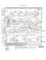
AMSTRAD
CB-901
SERVICE MANUAL
www.meetthebreakers.co.uk
Transmitter Alignment
CRYSTAL OSCILLATOR ALIGNMENT 10.240MHz
Connect Frequency counter to Pin 11 of U1 through 100pF Ceramic Capacitor
Adjust L2 for 10.240000MHz +/- 50Hz.
VCO ALIGNMENT
Set radio to channel 1
Measure voltage between R6/C9 junction and ground
Adjust T1 to read 2.0V
Set radio to Transmit
Adjust CT1 to read 2.0V.
Set radio to channel 40 (TX)
Check for voltage of 4 to 5V
RF POWER ALIGNMENT
Set radio to channel 20
Set 10dB attenuator switch at 'IN' position.
Preset cores of T2, T3 and T4 3 turns inside from top
Preset core of L4 1 turn counter-clockwise from the bottom
Preset L8 1 turn outside the top
Set unit to Transmit
Adjust T2, T3, T4, L4 and L8 for maximum output on oscilloscope and wattmeter
RF POWER CHECK
Set radio to channel 20
Set radio to transmit
Check power output is between 3.7W and 4.0W
Check that current drain is less than 1.6A.
Put attenuation switch to 'out' position
Check output power is between 0.2W and 0.4W
Check that current drain is less than 0.7A.
Repeat the steps above for channel 1 and channel 40
FREQUENCY ALIGNMENT
Set radio to channel 20
Set unit to Transmit
Adjust L2 to obtain 27.79125MHz +/- 300hz
Check channel 1 for 27.60125MHz +/- 300hz
Check channel 40 for 27.99125Mhz +/- 300hz
MODULATION ALIGNMENT
Set radio to channel 20
Set radio to Transmit
Apply 3mV @ 1.25kHz audio input to mic socket
Adjust RV3 for deviation for between 0.8kHz and 1.0kHz.
RF METER ALIGNMENT
Set 10dB switch out
Set unit to Transmit
Adjust RV1 to light red LED number 5.
Set 10dB switch in
All LEDS should now be lit.
Receiver Alignment
RECEIVER SENSIVITY ALIGNMENT
Set radio to channel 20
Connect voltmeter to RV2
Inject signal of 27.79125MHz with RF input signal of 4uV @ 1kHz +/- 1.5kHz deviation
Adjust T5, T6, T7, T8, T9, T10 for maximum voltage reading
Reduce RF input signal to zero
Adjust T11 for max noise output at speaker
Apply 1mV RF input signal and re-adjust T11 for max audio output and minimum distortion
SQUELCH ALIGNMENT
Set squelch control to maximum (clockwise)
Set RF gain control to maximum (clockwise)
Apply 7uV RF signal with 1kHz +/- 1.5kHz deviation
Adjust RV5 so that output from speaker just disappears
S METER ALIGNMENT
Set radio to channel 20
Apply 100uV from signal generator
Adjust RV2 so that green LED lights.