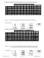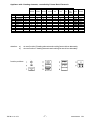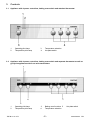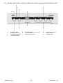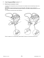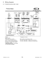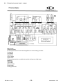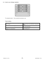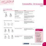
1
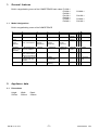
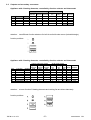
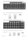
SERVICE MANUAL COOKING COMPETENCE Basic class © AEG Hausgeräte GmbH Muggenhofer Straße 135 D-90429 Nürnberg Germany Fax +49 (0)911 323 1420 TSE - N Edition: 01.01 Publ.-Nr.: 599 50 86 62 685 EN Table of contents 1. 1.1 General features ............................................................................................................. 3 Model designations ......................................................................................................... 3 2. 2.1 2.2 Appliance data................................................................................................................. 3 Dimensions ..................................................................................................................... 3 Outputs and secondary consumers ............................................................................... 4 3. 3.1 3.2 3.3 Controls .......................................................................................................................... 8 Appliance with 4 power controllers, baking oven switch and attached thermostat ......... 8 Appliance with 4 power controllers, baking oven switch and separate thermostat as well as pyrolysis appliances with 2 set value transmitters .......................................................... 8 Appliance with 4 power controllers, baking oven switch and separate thermostat and clock 9 4. 4.1 4.1.1 4.1.2 4.1.3 4.2 4.2.1 4.2.2 4.2.3 4.2.4 4.2.5 Component data ........................................................................................................... 10 Appliance without pyrolysis ........................................................................................... 10 Power controller ............................................................................................................ 10 Thermostat ................................................................................................................... 11 Clock (simple electronic timer) ..................................................................................... 12 Appliances with pyrolysis .............................................................................................. 13 Door lock ....................................................................................................................... 13 Micro switch for telescopic runner ................................................................................ 15 Temperature and function controllers ........................................................................... 15 Temperature sensor ..................................................................................................... 16 Prisma basic power board ............................................................................................ 17 5. Operation of the setting and operating units ................................................................. 18 5.1 Setting/modifying the time ............................................................................................. 18 5.1.1 Setting/modifying the time ............................................................................................. 18 5.1.2 Use of automatic function .............................................................................................. 19 5.1.3 Short time ...................................................................................................................... 21 6. 6.1 6.2 6.3 6.4 Technical equipment ..................................................................................................... 23 Fan running on function ................................................................................................ 23 Pyrolysis ....................................................................................................................... 24 Measures to prevent wrong electrical connection ......................................................... 25 Thermal link .................................................................................................................. 25 7. 7.1 7.2 Fault diagnosis/What to do if ? .................................................................................. 26 Measuring the temperature sensor ............................................................................... 26 Test of doorlock ............................................................................................................ 27 8. 8.1 8.2 Wiring diagrams ............................................................................................................ 28 Prisma basic power board input ................................................................................ 28 Prisma basic power board output .............................................................................. 29 9. 9.1 9.2 9.3 9.4 9.5 9.6 Service tips ................................................................................................................... 30 Unhinging and dismantling the baking oven door .......................................................... 30 Removing the two-part housing cover .......................................................................... 32 Demounting the Prisma basic power board.................................................................. 32 Demounting the temperature sensor ............................................................................ 33 Demounting the door lock ............................................................................................. 33 Help in case of baking complaints................................................................................. 35 TSE-N 01.01 A. B. -2- 599 50 86 62 EN 1. General features 1.1 Built-in ranges/baking ovens of the COMPETENCE basic class: E 1000-1 E 3000-1 E 4000-1 E 4100-1 E 4200-1 E 3040-1 E 4040-1 Model designations B 3000-1 B 4100-1 B 3040-1 B 4140-1 Built-in ranges/baking ovens of the COMPETENCE ( st 1 letter st 1 number nd 2 number rd 3 number Product group E built-in range, electrical Type of heating Equipment I Equipment II 1-1-Basic/ BasicPlus, conventional 0-without specific equipment 0-without specific equipment B-Built-in 2- Basic/Basic-Plus, 1-Clock baking oven, with ring radiator electrical 3- Basic/ BasicPlus, multi function without ring radiator 4- Basic-Plus, multi function with ring radiator 1-Vitratherm th 4 number th 5 number Equipment III Sales channel 0-without 0 specific equipment 1-additional equipment 1-specific model l : nd 2 letter Colour/design d-dark brown w-white 2-Steam b-black 3-Meat thermometer m-stainless steel 4-pyrolytic cleaning 2. Appliance data 2.1 Dimensions Height 595mm TSE-N 01.01 A. B. Width 592mm Depth 544mm -3- 599 50 86 62 EN 2.2 Outputs and secondary consumers Appliance with 3 heating elements, controlled by function selector and thermostat heating elements (Watt) small loads (Watt) grill top bottom cooling oven element element element fan lamp Pos. Function Symbol 1900 1000 1000 20 40 0 off A 1 oven lamp B X 2 top/bottom E X X X X 3 grill H X X X X attention: power current Watt Ampere 40 2060 2960 0,2 9,0 12,9 two different function selectors for built in and built under ovens (industrial design) function positions Appliance with 3 heating elements, controlled by function selector and thermostat heating elements (Watt) small loads (Watt) grill top bottom cooking cooling oven element element element fan fan lamp Pos. Function Symbol 1900 1000 1000 40 20 40 0 off A 1 oven lamp B X 2 hot air C X X X X X 3 top/bottom E X X X X 4 bottom K X X X 5 grill H X X X X 6 infraroasting G X X X X X attention: power current Watt Ampere 40 2100 2060 1060 2960 3000 0,2 9,1 9,0 4,6 12,9 13,0 at oven function G heating elements and cooking fan are driven alternately function positions TSE-N 01.01 A. B. -4- 599 50 86 62 EN Appliance with 3 heating elements, controlled by function selector and thermostat Pos. 0 1 2 3 4 5 6 7 8 Function off oven lamp hot air top/bottom bottom defrost grill 1 grill 2 infraroasting attention: heating elements (Watt) small loads (Watt) grill top bottom cooking cooling oven power current element element element fan fan lamp Watt Ampere Symbol 1900 1000 1000 40 20 40 A B X 40 0,2 C X X X X X 2100 9,1 E X X X X 2060 9,0 K X X X 1060 4,6 S X X 80 0,3 I X X X 1960 8,5 H X X X X 2960 12,9 G X X X X X 3000 13,0 at oven function G heating elements and cooking fan are driven alternately function positions Appliance with 3 heating elements, controlled by function selector and thermostat heating elements (Watt) small loads (Watt) grill top bottom cooking cooling oven element element element fan fan lamp Pos. Function Symbol 1900 1000 1000 40 20 40 0 off A 1 oven lamp B X 2 hot air C X X X X X 3 top/bottom E X X X X 4 bottom K X X X 5 top J X X X 6 defrost S X X 7 grill 1 I X X X 8 grill 2 H X X X X 9 infraroasting G X X X X X attention: power current Watt Ampere 40 2100 2060 1060 1060 80 1960 2960 3000 0,2 9,1 9,0 4,6 4,6 0,3 8,5 12,9 13,0 at oven function G heating elements and cooking fan are driven alternately function positions TSE-N 01.01 A. B. -5- 599 50 86 62 EN Appliance with 4 heating elements, controlled by function selector and thermostat heating elements (Watt) small loads (Watt) grill top bottom rear cooking cooling oven element element element element fan fan lamp Pos. Function Symbol 1900 1000 1000 2400 40 20 40 0 off A 1 oven lamp B X 2 solo hot air C X X X X X 3 multi hot air D X X X X 4 top/bottom E X X X 5 bottom K X X X 6 defrost S X X 7 grill 1 I X X X 8 grill 2 H X X X X 9 infraroasting G X X X X X attention: power Watt current Ampere 40 2100 2500 2060 1060 80 1960 2960 3000 0,2 9,1 10,9 9,0 4,6 0,3 8,5 12,9 13,0 at oven function G heating elements and cooking fan are driven alternately function positions Appliance with 3 heating elements, controlled by Prisma Basic Electronic heating elements (Watt) small loads (Watt) grill top bottom cooking cooling door lock oven element element element fan fan system lamp Pos. Function Symbol 1900 1000 1000 40 20 5 40 0 off A 1 oven lamp B X 2 hot air C X X X X X 3 top/bottom E X X X X 4 infraroasting G X X X X X 5 grill 2 H X X X X 6 grill 1 I X X X 7 bottom K X X X 8 defrost S X X 9 pyrolytic P X X X X X - attention: a) b) power current Watt Ampere 40 2105 2065 3005 2965 1965 1065 80 2970 0,2 9,2 9,0 13,1 12,9 8,5 4,6 0,3 12,9 at oven function G heating elements and cooking fan are driven alternately at oven function P heating elements and cooking fan are driven alternately function positions TSE-N 01.01 A. B. -6- 599 50 86 62 EN Appliance with 3 heating elements, controlled by Prisma Basic Electronic heating elements (Watt) small loads (Watt) grill top bottom rear cooking cooling oven door power current. element element element element fan fan lamp lock Watt Ampere system Pos. Function Symbol 1900 1000 1000 2400 40 2% 40 5 0 off A 1 oven lamp B X 40 0,2 2 solo hot air C X X X X X 2105 9,2 3 multi hot air D X X X X 2505 10,9 4 top/bottom E X X X X 2065 9,0 5 infraroasting G X X X X X 3005 13,1 6 grill 2 H X X X X 2965 12,9 7 grill 1 I X X X 1965 8,5 8 bottom K X X X 1065 4,6 9 defrost S X X 80 1,3 10 pyrolytic P X X X X X 2970 12,9 attention: a) b) at oven function G heating elements and cooking fan are driven alternately at oven function P heating elements and cooking fan are driven alternately function positions TSE-N 01.01 A. B. -7- 599 50 86 62 EN 3. Controls 3.1 Appliance with 4 power controllers, baking oven switch and attached thermostat 1 2 3.2 Operating pilot lamp Temperature pilot lamp 3 4 Temperature selection Hot plate switch Appliance with 4 power controllers, baking oven switch and separate thermostat as well as pyrolysis appliances with 2 set value transmitters 1 2 Operating pilot lamp Temperature pilot lamp TSE-N 01.01 A. B. 3 4 Baking oven functions 5 Temperature selection -8- Hot plate switch 599 50 86 62 EN 3.3 Appliance with 4 power controllers, baking oven switch and separate thermostat and clock 1 2 3 4 Function display Operating pilot lamp Temperature pilot lamp Temperature display TSE-N 01.01 A. B. 5 6 7 Time display and function lamps Hot plate display Baking oven functions -9- 8 9 10 Temperature selection Clock functions Hot plate switch 599 50 86 62 EN 4. Component data 4.1 Appliance without pyrolysis 4.1.1 Power controller Fig. Power controller Fig. Switch in OFF position Input voltage 230 V Fig. Performance characteristic K1 Knob position % ED Switching on period in percent 100 % corresponds to a switching on period of 41 seconds TSE-N 01.01 A. B. - 10 - 599 50 86 62 EN The hot plates are controlled via the bimetallic contact P 1-2. The input voltage of 230 V is applied here. Depending on the position of the knob, this contact determines how often the hot plate is switched on or off during a certain unit of time by cycling the maximum heating power (230 V or 0 V between contact 2 and 4) (refer to performance characteristic). Continuous operation at max. heating power is hot plate 9. The power characteristic shows the power controller in cycling mode. The average switching on period for each knob position can be read off in % of the cycled and/or max. power. 4.1.2 Thermostat Fig. Thermostat Fig. Temperature values TSE-N 01.01 A. B. - 11 - 599 50 86 62 EN Wiring diagram with spindle position; stop, left Fig. Wiring diagram The temperature can be selected according to the knob position. After beginning of work, contact 1-2 is closed. To check the thermostat, measure the temperature in the muffle. Determine the following temperatures: Hot air 160 °C ± 15 °C Conventional 200 °C ± 15 °C Pyrolysis 485 °C ± 20 °C If a temperature is found which is beyond the tolerance value, replace the thermostat. 4.1.3 Clock (simple electronic timer) Functions of the programmable clock: Display of time Short-time alarm-clock Automatic function for baking and frying times (For more details please refer to chapter 5, operation of setting and operating units) TSE-N 01.01 A. B. - 12 - 599 50 86 62 EN 4.2 Appliances with pyrolysis 4.2.1 Door lock The appliances with pyrolytic self-cleaning system are provided with a specific door lock system (Fig. 1) This system prevents opening of the baking oven door with the pyrolysis switched on. The lock system is operated with 2 heated bimetallic elements which move a bar into position which then either blocks or releases the lock lever at the baking oven door. The system functions during the pyrolysis process independent of the electrical voltage. The door lock is switched on at a temperature of the muffle centre of gravity (temperature in centre of baking oven) of 312 °C. Unlocking is at a temperature of approx. 180 °C via a Klixon (f11 in wiring diagram). The Klixon is arranged at the transverse beam beside the hot air motor (Fig. 2). Fig. 1, Door lock Fig. 2, Arrangement of Klixon Fig. Switching of door lock TSE-N 01.01 A. B. - 13 - 599 50 86 62 EN Fig. Door lock in unlocked state 2 E Inlet unlocking 3 Phase (230 V) 4 Inlet lock 33/34 Switch contacts (5 V, 100 mA) unlocked interlocked As soon as a voltage of 230 V is applied to the contacts 3 and 4, the bar A moves to the other side after 2 10 seconds and blocks the lock lever mechanically. The door cannot be opened. At the same time, the internal contact B opens and disconnects the lock path. The switch contacts 33/ 34 close and signal that door lock is completed. The electronic signal completes the lock signal. Internal contact C closes. For unlocking, a voltage of 230 V must be applied to contacts 2 and 3. The bar A moves backwards and releases the lock lever. The door can be opened provided that the contact f11 (Klixon) is closed. TSE-N 01.01 A. B. - 14 - 599 50 86 62 EN 4.2.2 Micro switch for telescopic runner The appliances with pyrolytic self-cleaning system are provided with a micro switch. The switch contact is interrupted with the grates suspended. Thus the self-cleaning function cannot be activated. The contact closes and self-cleaning is possible with the telescopic runners removed. 4.2.3 Temperature and function controllers Both with the temperature controller and the function controller, each angular degree of switch turning changes an existing voltage value and/or resistance value. Thus turning the switch results in a change of the existing temperature at the heater or of the mode of operation. Control is via the Prisma basic power board. Fig. Set value transmitter (function and temperature) 1=5V Fig. Temperature controller TSE-N 01.01 A. B. - 15 - 599 50 86 62 EN 1=5V Fig. Function controller Voltage in rest position: Data in % of the voltage applied nnung Pos.1 Pos. 2 Pos. 3 Pos. 4 Pos. 5 Pos. 6 Pos. 7 Pos. 8 Pos. 9 Pos. 10 0 to 4 7 to 15 18 to 26 29 to 37 40 to 18 52 to 60 63 to 71 74 to 82 85 to 93 96 to 100 4.2.4 Temperature sensor The temperature in the baking oven is measured by a temperature sensor (type PT 500) for appliances with control board. The sensor is provided at the rear of the appliance. It is used to transmit to the electronic systems the values for: cyclic heating the radiators until the selected temperature is reached; switch off the radiators in case of overheating of defective sensor; switching ON/OFF the cooling fan. Fig. Temperature sensor Fig. Electrical resistance of sensor depending on the ambient temperature TSE-N 01.01 A. B. - 16 - 599 50 86 62 EN 4.2.5 Prisma basic power board The Prisma basic power board controls the following range functions: Operation of radiators Operation of hot air blower Operation of cooling fan Optical display via signal lamps Automatic door lock during the pyrolysis process according to values to be selected at the temperature and function controller. The Prisma basic power board includes a power pack, 4 relays to control the heaters and other semi-conductor components and a fine-wire fuse (sluggish, 63 mA). Fine-wire fuse The fuse is arranged at the primary side of the power pack. If this fuse is defective, the appliance does not function and the displays and lighting system are out of service. Important: Appliances with Prisma basic power board are not provided with a test program! The supply voltage of 230 V for the power board and the consumers is applied at the main supply connection. For the other measuring points for small loads, door lock and heaters please refer to the block diagrams. TSE-N 01.01 A. B. - 17 - 599 50 86 62 EN 5. 5.1 Operation of the setting and operating units Setting/modifying the time 5.1.1 Setting/modifying the time Setting The baking oven functions only with the time set. The time function lamp flashes when the electrical connection is made or after a power failure. 1. Set the current time at the keys + or - . 2 Wait for 5 seconds. The flashing light goes out and the time set is displayed. Modifying 1. Press key ¿ until the time function lamp flashes. 2. Set the current time at the keys + or - . TSE-N 01.01 A. B. - 18 - 599 50 86 62 EN 3. Wait for 5 seconds. The flashing light goes out and the time set is displayed. 5.1.2 Use of automatic function Period of function 1. Press the ¿ key until the period function lamp flashes. 2. Set the desired cooking time at the keys + or - . 3. Wait for 5 seconds. The display returns to time. The period function lamp lights and the baking oven is ON immediately. When this time is elapsed, the function lamp flashes, an acoustic signal is given and the baking oven switches OFF. 4. Press any key to clear this signal. TSE-N 01.01 A. B. - 19 - 599 50 86 62 EN End 1. Press ¿ key until the end function lamp flashes. 2. Set the desired switching off time at the keys + or - 3. Wait for 5 seconds. The display returns to time. The end function lamp lights and the baking oven is ON immediately. When this time is elapsed, the function lamp flashes, an acoustic signal is given and the baking oven switches OFF. 4. Press any key to clear this signal. Combined period and end 1. Set the time required for cooking the meal at the period function. Here 1 hour. TSE-N 01.01 A. B. - 20 - 599 50 86 62 EN 2. Set the time at which the meal shall be ready at the end function. Here 02:05 p.m. The period and end function lamps light, the display shows the time of the day. Here 12:05 p.m. The baking oven switches on automatically at the time calculated. Here 01:05 p.m. And off after the set period is elapsed (02:05 p.m.). 5.1.3 Short time An acoustic signal is given after the short time is elapsed. 1. Press the ¿ key until the short time function lamp flashes. 2. Set the desired short time (max. 2 hours and 30 minutes) at the keys + or - . 3. Wait for 5 seconds. The display shows the remaining time. The short time function lamp lights. When this time is elapsed, the function lamp flashes and an acoustic signal is given. TSE-N 01.01 A. B. - 21 - 599 50 86 62 EN 4. Press any key to clear this signal. TSE-N 01.01 A. B. - 22 - 599 50 86 62 EN 6. Technical equipment 6.1 Fan running on function The appliances switch on automatically as soon as the baking oven is started. After having switched off the baking oven, the cooling fan continues to operate in order to cool down the appliance. Important: All appliances of this series are provided with this running on function. Appliances without electronic system, without clock: Appliances without electronic system, with clock: In these appliances the running on function of the fan is controlled via a Klixon which is provided at the rear of the muffle. The control system of the fan running on function functions via a limiter which is provided behind the baking oven switch in the cable harness. The fan running on function of all appliances with Prisma basic power board is controlled electronically. As these appliances are also provided with a pyrolysis feature, an additional resistance (Fig. 1) is installed which, however, is bridged during the pyrolysis mode. Thus the cross flow fan operates at a higher speed as long as this function is active. Fig. 1 Resistance increased speed r20.- resistance m2 - cross flow fan TSE-N 01.01 A. B. - 23 - 599 50 86 62 EN 6.2 Pyrolysis Fig. Heating up curve temperature/time P1: Heating time 150 min = pyrolysis 1 P2: Heating time 90 min = pyrolysis 2 Door locks at 312 °C, after 11 min Door unlocks at 204 °C, after 120 min (P2) or 180 min (P1) Centre of load 472 °C ± 5 °C The cooling fan is operated at high speed until the time of unlocking then at a lower speed. It switches off at approx. 130 °C residual heat in the muffle. TSE-N 01.01 A. B. - 24 - 599 50 86 62 EN 6.3 Measures to prevent wrong electrical connection If a range with pyrolytic self-cleaning system is connected wrongly, the micro processor at the Prisma basic power board recognises this error. It changes over into the fault mode. The fault is displayed by flashing pilot lamps in the switch panel. The heaters are dead. The connection error can be corrected. Then the range can be operated quite normally. Fig. Versions of connection 6.4 Thermal link A thermal link is provided in all appliances at the left side at the air duct, which switches off the device in case of overheating. Fig. Thermal link (Klixon) TSE-N 01.01 A. B. - 25 - 599 50 86 62 EN 7. Fault diagnosis/What to do if ? 7.1 Measuring the temperature sensor If a failure at the temperature sensor is assumed, the resistance can be checked by means of an ohmmeter. The resistance of the temperature sensor should be 500 600 ohms at room temperature. Make sure to measure the insulation resistance between the metallic housing and each connection terminal. The resistance should be higher than 2 MOhms. Refer to chapter 4.2.5 of Prisma basic power board for failures of consumers and door lock. TSE-N 01.01 A. B. - 26 - 599 50 86 62 EN 7.2 Test of doorlock Activating To enter into door lock test the operator must execute the following actions: 1. Power on the oven with oven function knob not in 0 position (oven goes to OVEN-SAFE state). It can exit from this state by setting oven function knob in 0 position (see Chapter EXIT PROCEDURE). Apart this position, in OVEN_SAFE the user can freely move knobs and the oven does not perform any action. 2. Move oven function knob to oven function 9. 3. Move temperature selection knob to max position. 4. Move oven vunction knob to oven function 1. 5. Move temperature selection knob to zero position. At this point the oven is in service mode (OVEN-SERV-TEST state). This information is displayed to the operator by changing led status from OVEN_SAFE mode (Pilot lamp on, Temperatur lamp blinking at 1 Hz) to another one that is pilot lamp blinking 1 Hz and temperatur lamp off. Each one of the actions 3, 4 and 5 must be done in short time (10 seconds) after the previous action. If the operator does not perform each operation within the time-out, the entering procedure is aborted. At this point the oven remains in OVEN_SAFE state and it is possible to restart the entering procedure from the action 2. 6. Move knov to position 2 to start door lock test. Deactivating Door lock test can bei paused moving the knob from position 2 to another position )different from 0 position). If the operator moves the knob to 0 position, the oven exits from SERVICE MODE and goes to normal OVEN-STD-BY state. During SERVICE MODE, if the operator does not move the knobs at least every 5 minutes, the oven automatically exits SERVICE MODE and goes to normal OVEN_SAFE state. In this way we avoid the possibility that the operator leaves the oven in SERVICE MODE. In any case of the oven is switched off the SERVICE MODE is cancelled. Fault code for Prisma-Electronics The yellow lamp flashes 1X 2X 4X 5X 6X 7X cannot lock cannot unlock temperature sensor defect selection point temperature too high electronics too hot wrong connection The red lamp flashes only as a counter with 10 second intervals. TSE-N 01.01 A. B. - 27 - 599 50 86 62 EN 8. Wiring diagrams 8.1 Prisma basic power board input PT500 Master switch Telescopic runner switch Knob 1: Oven function selector Knob 2: Oven temperature setting Red lamp: T° lamp, oven heating or high temperature Yellow lamp: Pilot lamp, hob active or oven function selected TSE-N 01.01 A. B. Temperature sensor Micro switch for telescopic runner Set value transmitter baking oven functions Set value transmitter baking oven temperature - 28 - 599 50 86 62 EN 8.2 Prisma basic power board output Main Supply Switched Phase f2: thermal protection for the whole appliance to avoid heating overload Cooling fan Low speed High speed Oven Lamps Input unlock f11:thermal protection to unable door unlock during oven high temp. Input lock Grill heater Top heater Bottom heater Rear Heater Heating Elements TSE-N 01.01 A. B. - 29 - 599 50 86 62 EN 9. Service tips 9.1 Unhinging and dismantling the baking oven door Unhinging the baking oven door 1. 2. 3. 4. Open the door fully. Tilt open the clamping lever at both door hinges completely (1). Hold door sides with both hands and close for approx. ¾ overriding the resistance (2). Withdraw door from baking oven. Hinging the baking oven door 1. 2. 3. 4. 5. Hold door sides with both hands seen from the handle side. Keep door at an angle of 60°. Push in door hinges into the two recesses at the bottom of the baking oven as far as they will go (1). Lift door upwards until a resistance is felt and then open it fully (2). Tilt back the clamping levers into their initial position at the door hinges (3) Demounting the top door glass 1. 2. 3. Unhinge baking oven door. Hold top glass pane at its lower edge and push it towards the baking oven door handle against the spring pressure until it is exposed on bottom. (1). Lift pane from below and withdraw (2). TSE-N 01.01 A. B. - 30 - 599 50 86 62 EN Demounting the middle door glass 1. 2. Hold middle glass pane at its lower edge and push it towards the baking oven door handle against the spring pressure until it is exposed on bottom (1). Lift and withdraw pane (2). Inserting the middle door glass 1. 2. Insert middle glass pane into the door section at the handle side inclined from top (1). Lower glass pane (2) and push it towards the bottom edge of door as far as it goes below the bottom holder. Inserting the top door glass 1. 2. Insert top glass pane into the door section at the handle side inclined from top (1). Lower pane (2). Place pane at the handle side in front of the holding section of the bottom edge of door against the spring force and push it below the holding section. TSE-N 01.01 A. B. - 31 - 599 50 86 62 EN 9.2 Removing the two-part housing cover 1. Loosen the two right and left mounting bolts 2. Lift front half of cover 9.3 Demounting the Prisma basic power board 1. Loosen the 4 mounting bolts of the housing cover TSE-N 01.01 A. B. - 32 - 599 50 86 62 EN 2. Withdraw cables. 9.4 Demounting the temperature sensor Loosen the two mounting bolts and withdraw the temperature sensor. 9.5 Demounting the door lock The door lock is arranged in the ranges at the front left side. It is accessible from top. TSE-N 01.01 A. B. - 33 - 599 50 86 62 EN 1. Loosen lateral mounting bolts 2. Remove door lock TSE-N 01.01 A. B. - 34 - 599 50 86 62 EN 9.6 Help in case of baking complaints The insertion levels 1 5 are counted from bottom to top. Tips for baking The cake collapses (becomes sticky, soggy, water stripes) The cake bottom is too light Cake with moist top coat/cake is not baked through, not evenly brown TSE-N 01.01 A. B. Check recipe, use less liquid, observe agitation times, above all when using kitchen mixers. Use a darker mould the next time or insert cake one level lower. Next time bake at a lower temperature and longer baking time. - 35 - 599 50 86 62 EN