1
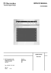
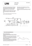
STR150®
0FL-4070-000
Wall Module with Display
User's Manual
MOUNTING, CABLES
CONNECTING
Connecting STR150 to a TAC Xenta 100 Family
Controller
Cables
STR150
Cables
TAC Xenta Controller
(101-VF, 102-ES,103-A or 104-A)
Cables
Cables
Mode 11
Data 12
M 13
D1
X1
M
Wiring
Cable type ............................. Twisted pair, unshielded
Cable size ................................. Min 0.7 mm2 (19 AWG)
Distance ............................................ Max 30 m (100 Ft)
To avoid base-plate deformation, be careful when
tightening the mounting screws. Note that the
enclosed screws are mainly intended for the US
and Australian markets.
REMOVING THE CORE
The core panel is
attached to the baseplate using two
hinges. Remove the
core panel by pushing
the bottom of the core
panel upwards, then
unhinging the core
panel from the baseplate.
ATTACHING/REMOVING THE FRONT
The front panel is
attached to the baseplate using four clamps,
two at the top of the front
panel and two at the
bottom.
When removing the front
panel use a screwdriver
(or similar) and push
gently to unhook the
clamps at the top or
bottom of the front panel.
NOTE: This equipment has been tested and found to comply with the limits for a Class B digital device, pursuant to part 15 of the FCC Rules.
These limits are designed to provide reasonable protection against harmful interference in a residential installation. This equipment generates,
uses and can radiate radio frequency energy and, if not installed and used in accordance with the instructions, may cause harmful interference to
radio communications. However, there is no guarantee that interference will not occur in a particular installation. If this equipment does cause
harmful interference to radio or television reception, which can be determined by turning the equipment off and on, the user is encouraged to
try to correct the interference by one or more of the following measures:
-Reorient or relocate the receiving antenna.
-Increase the separation between the equipment and receiver.
-Connect the equipment into an outlet on a circuit different from that to which the receiver is connected.
-Consult the dealer or an experienced radio/TV technician for help.
0FL-4070-000, 13 Dec 2002
English
1 (2)
USER INTERFACE
By pushing the button again it is possible to circle
between the modes. The fan symbol resumes a steady
light after five seconds, confirming the chosen mode.
Adjusting the Room Temperature
The increase button increases the temperature
setpoint in steps of 0.1 or 0.5°C (0.2 or 1.0°F).
The decrease button decreases the temperature
setpoint in steps of 0.1 or 0.5°C (0.2 or 1.0°F).
Changing to Occupied Mode
The bypass button is used to change from standby
(economy) or unoccupied mode to comfort mode.
When entering comfort mode, the symbol on the
display shows a steady light. When the bypass time
expires, the symbol returns to its previous status again,
provided that the feedback mode is connected. Otherwise
the symbol returns to the Off status after two hours.
Fan Speed Symbols
On/Off Fan
Two-Speed Fan
Three-Speed Fan
Auto
Auto
Auto
Off
Off
Off
On
Fan Speed 1
Fan Speed 1
Fans Speed 2
Fan Speed 2
Adjusting the Fan Speed
The fan button is used to override the automatic fan
control. The different fan modes are represented by
the fan group symbol on the display.
Fan Speed 3
When the fan button is pushed, the fan symbol on the
display starts to flash, indicating that the mode can be
changed.
CONFIGURATION
Enter Configuration Mode
Push the fan and bypass buttons simultaneously for 2
seconds to enter P0. In P0, hold down the bypass button
and push the fan button three times.
Selecting Parameters and Values
In configuration mode, the two digits farthest to the left on
the display show the parameters, while the two digits
farthest to the right shows the value.
The wrench symbol is lit when the STR150 is in
configuration mode.
Press the fan button repeatedly to select different
parameters.
Change the value by pressing the increase or decrease
buttons.
Exit Configuration Mode
Push the fan and man button for 2 seconds. The timeout
will exit configuration mode if idle.
Configuration Options
Parameter
Note that P0 is also
used for display
test.
Function
Value/Range
Default value
P0
Software Version
-
-
P1
°C or °F temperature display
1=°C, 2=°F
1=°C
P2
Reference temperature (Reftemp)
15-30°C / 60-90°F
22°C / 72°F
P3
Setpoint or room temp. as default
1=Setpt, 2=Room
1= Setpt
P3
Timeout
5-90 seconds
10 seconds
P5
Fan settings
0= No fan
1= On/Off fan
2= Two-speed fan
3= Three-speed fan
3= Three-speed fan
Press the increase
button when P0 is
displayed to show
all symbols in the
display.
Press the decrease
button when P0 is
displayed to turn off
all symbols in the
display.
P6
Room temperature and setpoint
display resolution
0.1 or 0.5 °C
0.2 or 1.0 °F
0.5 °C
0.2 °F
P7
Max adjustable setpoint span above or
below Reftemp (P2).
+/- 0 - +/- 5°C
+/- 0 - +/- 10°F
+/- 3° or +/- 6°F
P8
Bypass button and occupancy indication
When = 2, no bypass command is sent
to the controller
1= Symbol on, off
Default 1=on, off
or flashing
or flashing
2= Symbol always off
Trademarks and registered trademarks are the property of their respective owners.
TAC Vista®, TAC Menta®, TAC Xenta® and Talking Buildings® are registered trademarks of TAC AB. LonMark® and LonWork® are registered trademarks of the Echelon Corporation.
Windows® is a registered trademark of Microsoft.
www.tac-global.com
2 (2)
English
0FL-4070-000, 13 Dec 2002