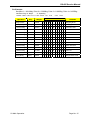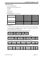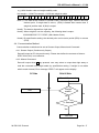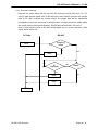
1
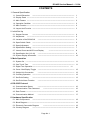
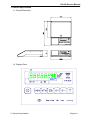
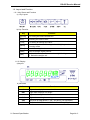
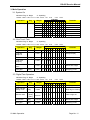
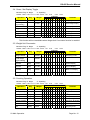
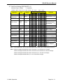
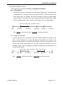
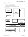
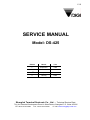
V1.0
SERVICE MANUAL
Model: DS-425
Edition
Month
Year
st
September
1998
2nd
December
1998
3rd
April
2001
January
2002
1
4
th
Shanghai Teraoka Electronic Co., Ltd. --- Technical Service Dept.
Ting Lin Industrial Development Zone Jin Shan District, Shanghai P. R. China 201505
Tel: +86-21-5723-4888
Fax: +86-21-5723-9330
E- mail: [email protected]
DS-425 Service Manual --- V1.04
CONTENTS
1. General Specification
1.1. Overall Dimension
---------------------------------------------------------------------------- 1
1.2. Display Panel -------------------------------------------------------------------------------------
1
1.3. Main Feature -------------------------------------------------------------------------------------- 2
1.4. Operation Condition ---------------------------------------------------------------------------- 2
1.5. Main Function -------------------------------------------------------------------------------------- 2
1.6. Layout And Function ---------------------------------------------------------------------------- 3
2. Initial Set-Up
2.1. Stopper Screws
2.2. Adjustment
---------------------------------------------------------------------------- 4
-------------------------------------------------------------------------------------- 5
2.3. Location of the SPAN SW
------------------------------------------------------------------ 5
2.4. Span Switch Check
---------------------------------------------------------------------------- 6
2.5. Span Adjustment
---------------------------------------------------------------------------- 6
2.6. Specification Setting ---------------------------------------------------------------------------- 7
2.7. Internal Count and A/D Count Display
2.8. Specification List (*V1.04)
----------------------------------------------
8
------------------------------------------------------------------ 8
2.9. System Display Information ------------------------------------------------------------------ 10
3. Main Operation
3.1. System On ---------------------------------------------------------------------------------------- 11
3.2. One Touch Tare
---------------------------------------------------------------------------- 11
3.3. Digital Tare Operation ------------------------------------------------------------------ 11
3.4. Gross / Net Display Toggle
------------------------------------------------------------------ 12
3.5. Weight Unit Conversion
------------------------------------------------------------------ 12
3.6. Counting Operation
---------------------------------------------------------------------------- 12
3.7. Set-Point Setting
---------------------------------------------------------------------------- 13
3.8. Set-Point Alarm Function
------------------------------------------------------------------ 14
4. RS-232C Protocol
4.1. Communication Specs
------------------------------------------------------------------ 16
4.2. Communication Text Command
--------------------------------------------------------
16
4.3. Data Format ---------------------------------------------------------------------------------------
16
4.4. Communication Method
------------------------------------------------------------------ 17
5. Hardware Specification
5.1. Main Components
---------------------------------------------------------------------------- 19
5.2. Block Diagram -------------------------------------------------------------------------------------- 19
5.3. Electronic Connection Diagram
5.4. Circuitry Diagram
--------------------------------------------------------- 19
---------------------------------------------------------------------------- 20
Page No. 1
DS-425 Service Manual
1. General Specification
1.1. Overall Dimension
1.2. Display Panel
01 General Specification
Page No. 1
DS-425 Service Manual
1.3. Main Feature
•
Model
•
Display Resolution : 1/1000, 1/1500, 1/2000, 1/2500, 1/3000, 1/5000, 1/6000,
: DS-425
1/7500, 1/10000, 1/15000, 1/20000, 1/25000, 1/30000
•
Internal Resolution : 1/250000, 1/300000
•
Capacity
: 300g, 600g, 1.5kg, 3kg, 6kg, 15kg, 30kg
•
Display Tube
: Liquid Crystal (With back-light new design GD-584)
•
Weight display
: 8 Segment , 6 Digit
•
Weigh Unit
: 4 Symbol (kg, g, lb., oz.)
•
Indicators
: 4 Set Point (S1, S2, S3, S4), 8 indicators for Zero, Net, Std,
U.W, U.C, MEM, BATT, PCS
•
Interface
: RS-232(OPTIONAL)
•
Load cell
: 300g-K-Type,600g-30Kg N-Type.
•
Mechanical Detail
: Housing DS-425W, DS-422 Keyboard
•
Physical Dimension : (L)321 * (W)256 * (H)80 mm
Platter Size: 105mm x 160mm (300g)
205mm x 250mm (600g Upwards)
1.4. Operation Condition
•
Power Source
: AC 220V (+10%,-15%) 50HZ/60HZ (Factory Set)
•
Temperature
: 0°C to 40°C
•
Humidity
: <85% RH
•
Microcomputer
: Atmal AT89C52, 8bit
•
Display Device
: Liquid Crystal Display (With back-light GD-584)
•
LCD Display Drive : NEC uPA7225G
•
A/D Board
: STB-0054 A/D. (DS-422), New A/D Cover
1.5. Main Function
•
Basic Weight Unit: g, kg
•
Weight Unit Toggle: g, lb, and oz, kg, lb, and oz
•
Counting Function
•
RS-232C communication
01 General Specification
Page No. 2
DS-425 Service Manual
1.6. Layout and Function
1.6.1. Key Sheet and Function
a) Key Layout
b) Key Function
Key
Function
[On/Off]
[ReZero]
[Tare]
For turning the scale ON and OFF
Resetting the scale to zero.
[Mode]
Used to entry into the following modes: Weighing mode or
Counting mode.
[Enter]
Used for storing the data.
[Shift]
Used to change digital position.
[INC]
1) Used for increase data value when digit blinking;
2) Switch the weight unit.
For setting & clearing tare value.
1.6.2. Display
a) Layout
b) Indicators
Indicator
Function
->0<-
Light when display is zero and stable
NET
Light when displays net weight
~
Light when weight is stable
U.C
Light when working in counting mode
SAF
Set-point ALAME Mode is ”ON”, and during Fill Application
SAC
Set-point ALAME Mode is “ON”, At Check Weight Application
01 General Specification
Page No. 3
DS-425 Service Manual
3. Main Operation
3.1. System On
Indication Flag: B - Bright
S - Sparkling
1-ZERO 2-NET 3-STD 4-U.C 5-SAF 6-SAC 7-S1
Operation
Press [On/Off]
Key
[On/Off]
8-S2
9-S3
10-S4
Indicator
1 2 3 4 5 6 7 8 9 10
Weight
Remarks
dS-425
Model Name
Ur. 1.00
Software Version
000000
Segment Checking
111111
999999
0.0000
kg B
B
Weighing Mode
3.2. One Touch Tare
Indication Flag: B - Bright
S - Sparkling
1-ZERO 2-NET 3-STD 4-U.C 5-SAF 6-SAC 7-S1
Operation
Key
8-S2
9-S3
10-S4
Indicator
1 2 3 4 5 6 7 8 9 10
Weight
Weight Stable
0.0000
kg
Load tare
weight on
1.2220
Remarks
B
Weighing mode
kg
B
Weight display
0.0000
kg
B B
Load more
weighing
1.0000
kg
B B
Remove all
items
-1.2220
kg
B B B
Minus tare weight
0.0000
kg
B
Weighing mode
Excute tare
Tare clear
[Tare]
[Tare]
B
Net display
B
Note: This operation is based on No Auto TARE CLEAR, SPEC10 BIT1=0.
3.3. Digital Tare Operation
Indication Flag: B - Bright
S - Sparkling
1-ZERO 2-NET 3-STD 4-U.C 5-SAF 6-SAC 7-S1
Operation
Key
Weight
8-S2
9-S3
10-S4
Indicator
1 2 3 4 5 6 7 8 9 10
Remarks
Weight Stable
0.0000
kg B
B
Weighing mode
Enter into tare
[Shift]
setting mode
0.0000
kg B
B
Right digit is blinking
kg B
B
Tare weight set
Set tare value
[Shift]
[Shift]
[INC]
0.00100
Excute tare
[Tare]
-0.00100 kg B B B
Minus tare weight
Tare clear
[Tare]
0.0000
Weighing mode
kg B
B
Note: This function is available when SPEC10 BIT2=1 only.
03 Main Operation
Page No. 11
DS-425 Service Manual
3.4. Gross / Net Display Toggle
Indication Flag: B - Bright
S - Sparkling
1-ZERO 2-NET 3-STD 4-U.C 5-SAF 6-SAC 7-S1
Operation
Key
8-S2
9-S3
10-S4
Indicator
1 2 3 4 5 6 7 8 9 10
Weight
Remarks
Weight Stable
0.0000
kg B
B
Weighing mode
Load weight
(eg.0.6000kg)
0.6000
kg
B
Gross weight display
Excute tare
[Tare]
0.0000
kg
B B
Toggle
[INC]
0.6000
kg
B
Gross Weight display
0.0000
kg B
B
Weighing mode
Remove item
Net display
Toggle
[INC]
-0.6000
kg B B B
Net weight
Tare clear
[Tare]
0.0000
kg B
Weighing mode
B
Note: The function is available when SPEC11 BIT0=1 only.
This function will be unavailable when Weight Unit Conversion function is enabled.
3.5. Weight Unit Conversion
Indication Flag: B - Bright
S - Sparkling
1-ZERO 2-NET 3-STD 4-U.C 5-SAF 6-SAC 7-S1
Operation
Key
0.0000
Load weight
(eg.0.6000kg)
0.6000
Convert
[INC]
1.3225
Convert
[INC]
21.165
Convert
[INC]
0.6000
Remove items
0.0000
9-S3
10-S4
Indicator
1 2 3 4 5 6 7 8 9 10
Weight
Weight Stable
8-S2
k
g
k
B
Weighing mode
B
B
g
lb
o
z
k
g
k
g
Remarks
B
B
Pound display
B
Ounce display
B
Basic unit display
B
Weighing Mode.
Note: This operation is available when SPEC15 = 0100 or 1100 only.
3.6. Counting Operation
Indication Flag: B - Bright
S - Sparkling
1-ZERO 2-NET 3-STD 4-U.C 5-SAF 6-SAC 7-S1
Operation
Key
Weight Stable
Press [MODE]
[Mode]
9-S3
10-S4
Indicator
1 2 3 4 5 6 7 8 9 10
Weight
0.0000
8-S2
kg B
B
Remarks
Weighing mode
Add 32
B
Sample number 32
Change number
[Shift][Shift] Add 32
B
2nd digit selected
Chang value
[INC][INC]
Add 52
B
Sample number 52
Confirm
[*]
0.0000
kg B
B B
Sample weight
0.6000
kg
B B
Weight for all samples
Load 52 samples
Confirm
[*]
52
kg
B B
Counting mode
Exit
[Mode]
0.6000
kg B
B
Weighing mode
03 Main Operation
Page No. 12
DS-425 Service Manual
3.7. Set-Point Setting (SPEC8 BIT0 = 1)
Indication Flag: B - Bright
S - Sparkling
1-ZERO 2-NET 3-STD 4-U.C 5-SAF 6-SAC 7-S1
Operation
Key
Weight Stable
9-S3
10-S4
Indicator
1 2 3 4 5 6 7 8 9 10
Weight
0.0000
8-S2
kg B
B
Remarks
Weighing mode
Enter into
setting mode
[Mode]
[Mode]
SET-1
Confirm
[Enter]
0.0000
Value change
[Shift]
[INC]
0.0050
Confirm
[Enter]
SET-2
Point 2 setting
[Enter]
0.0000
kg
B
Set value
Value change
[Shift]
[INC]
0.0100
kg
B
Same method as
point 1 setting
*2)
Confirm
[Enter]
SET-3
kg
Confirm
[Enter]
0.0000
kg
Value Change
[Shift]
[INC]
0.0100
kg
Confirm
[Enter]
SET-4
kg
Confirm
[Enter]
0.0000
kg
B Set value
Value change
[Shift]
[INC]
0.0100
kg
Same method as
B
above
*4)
Confirm
[Enter]
0.0000
kg B
Set for Point 1
kg
kg
*1)
B
Set value
B
[Shift] key to select
the digit, [INC] key to
change the value of
digit selected
*1)
Set-Point 1 saved
*2)
Point 2 saved
*3)
B
Set value
*3)
B
Same procedure as
point 1 & 2 setting *3)
Point 3 saved
B
*4)
*4)
Point 4 saved and
back to weighing
mode
*4)
Note 1: The indicators S1, S2, S3, S4 will be lighted when setting the corresponding Set-Point.
Note 2: When the weight exceeds the value of Set-Point 1, the indicator S1 will light.
When the weight exceeds the value of Set-Point 2, the indicator S1 and S2 are light.
When the weight exceeds the value of Set-Point 3, S1, S2 and S3 are light.
When the weight exceeds Point 4, S1, S2, S3 and S4 are light.
03 Main Operation
Page No. 13
DS-425 Service Manual
3.8. Set-Point Alarm Function
This function has two methods: Filling and Weight Check Method.
3.8.1. Filling Method
Operator fills the item on the platter up to the target weight range. The target range
is determined by 2-set-point (set-point 2 and set-point 3) and continuously fast
alarm will be alert. So operator can know the weight is within the target-weight
range. Set point 1 and set point 2 may be programmed as a fine adjustment range.
The intermediate alarm notes to operator the weight is closed to target weight.
(Near mini. Target) (Mini. Target) (Max. Target)
Zero
Note:
Set point 1
Set point 2
continuous slow alarm
Set point 3
Set point 4
Full Span
continuous fast alarm
3.8.2. Weight Check Method
Operator places item on the platter and check (confirm) whether the weight of the
item is within allowable error range. Basically the allowable error range can be
defined via the setting of 2-set-points (For example: set point 2 and set point 3). And
also you can set the range within point 1 till point 2 and point 3 till point 4 is out of
allowable range. Then the operation can judge the weight error is allowable for not
via the sound of alarm.
(Out of Range)
Zero
Note:
03 Main Operation
Set point 1
Min.) (Allowable) (Max.)
Set point 2
Continuous slow alarm,
Set point 3
(Out of Range)
Set point 4
Full Span
Continuous fast alarm
Page No. 14
DS-425 Service Manual
For Example:
Set-point 1 = 0.0100kg, Point 2 = 0.0200kg, Point 3 = 0.0350kg, Point 4 = 0.0550kg
Indication Flag: B - Bright
S - Sparkling
1-ZERO 2-NET 3-STD 4-U.C 5-SAF 6-SAC 7-S1
Operation
Key
Weight Stable
8-S2
9-S3
10-S4
Indicator
1 2 3 4 5 6 7 8 9 10
Weight
Remarks
0.0000
kg B
B
0.0000
kg B
B
B
Load 0.0150kg
0.0150
kg
B
B
B
Fast alarm start
Load 0.0150kg
0.0300
kg
B
B
B B
Slow alarm start
Load 0.0150kg
0.0450
kg
B
B
B B B
Fast alarm start
Load 0.0150kg
0.0600
kg
B
B
B B B B Alarm off
Remove all item
0.0000
kg B
B
B
0.0000
kg B
B
B
Weight check method
Press [Enter]
Press [Enter]
[Enter]
[Enter]
Weighing Mode
Filling application
Load 0.0150kg
0.0150
kg
B
B B
Fast alarm start
Load 0.0150kg
0.0300
kg
B
B B B B
Slow alarm start
Load 0.0150kg
0.0450
kg
B
B B B B B
Fast alarm start
Load 0.0150kg
0.0600
kg
B
B B B B B B Alarm off
Remove all item
0.0000
kg B
B
B B
0.0000
kg B
B
Press [Enter]
03 Main Operation
[Enter]
Weight check mode
Page No. 15
DS-425 Service Manual --- V1.04
4. RS-232C Protocol
4.1. Communication Specs
Baud Rate: 2400, 4800, 9600, 19200.
Start Bit: 1
Stop Bit: 1
Data Length: 8
Parity Bit: None
4.2. Communication Text Command
Termination Code
CR
LF
0~9
- (Minus)
. (Period)
, (Comma)
0
4
Null
SOH
Data
Header Code
Stable sign
The end of data
The end of Text
Numeric data
Minus sign
Period
Comma
Net Weight
Tare Weight
Stable
Un-stable
0DH
0AH
(30H~39H)
2DH
2EH
2CH
30H
34H
00H
01H
4.3. Data Format
The SPECs to alter the supplement of header code and the status of weight stability
are newly added to specification setting. (Header Code Selection SPEC02 Bit 0,
Weight Stability Selection SPEC02 Bit 1)
4.3.1. Without header-code and weight stable code (Total 17 Bytes)
Net Weight
CR
Tare Weight
CR
LF
7 Byte
1byte
7 Byte
1 Byte
1 Byte
4.3.2. Without header-code and with weight stable code (Total 19 Bytes)
Stable status
CR
Net Weight
CR
Tare Weight
CR
LF
1 Byte
1 Byte
7 Byte
1byte
7 Byte
1 Byte
1 Byte
4.3.3. With header code and Without weight stability code (Total 19 Bytes)
Header
Net Weight
CR
Header
Tare Weight
CR
LF
1 Byte
7 Byte
1byte
1 Byte
7 Byte
1 Byte
1 Byte
4.3.4. With header and weight stability code (Total 21 Bytes)
Stable Code
CR
Header Code
Net
CR
Header Code
Tare
1 Byte
1 Byte
1 Byte
7 Byte
1byte
1 Byte
7 Byte
04 RS-232C Protocol
CR
LF
1 Byte 1 Byte
Page No. 16
DS-425 Service Manual --- V1.04
e.g.) With Header code and weight stability code
Net weight =-1,2340 Tare weight = 0,450 and weight is stable
Null
CR
0
-
0
1
,
2
3
0
CR
4
0
0
0
,
4
5
0
CR
LF
Note 1): The data format consists of (header code), minus/plus sign, numeric data and
decimal point. If weight data is minus, -(2DH) is added after header data. If
weight is positive data, 0(30H) is output.
Note2): The data is aligned from right side.
Note3): When weight is over the capacity, the following data is output:
0OV00000CR4???????CRLF (With Header Code)
Note4): By specification setting, the decimal point can be set to period (2EH) or comma
(2CH).
4.4. Communication Method
Communication method can be set as Stream Output, Manual and Command.
4.4.1. Stream Output (Continuously Output)
Data will output to PC side continuously. Please also define the contents of data on
SPEC 03 bit 0&1) is not effective.
4.4.2. Manual Command
Data will output when ↑ key pressed, user may select to output data right away or
hold the command until weight stable by specification setting. If weight is not stable
within certain interval, Error message “ERR C” will appear on the display.
PC Side
DS-425 Side
Manual Command
Text
Yes
Weight
Stable?
No
No
X. Seconds
Yes
Time Out
04 RS-232C Protocol
Page No. 17
DS-425 Service Manual --- V1.04
4.4.3. External Command
Data will be output when DS-425 receives the command (ACK 06H) form PC. PC
send a data request signal ACK to DS-425 side, then DS-425 transmits the weight
data to PC after received the request signal, the weight data will be transferred
immediately or hold the command till weight stable. If weight cannot be stable within
the certain interval (set by specification), DS-425 will transmit NAK (15H) to PC.
Note: If ACK signal is sent to DS-425 during digital tare or re-zero operation, NAK
signal will be sent to PC.
PC Side
DS-425
Weighing
Mode
ACK
No
Yes
NAK
No
X.
Seconds
No
Stable
Yes
NAK
Yes
Data
EOT
04 RS-232C Protocol
Page No. 18
DS-425 Service Manual --- V1.04
5. Hardware Specification
5.1. Main Components
•
Microcomputer: ATMAL AT89C52 8 bit
•
LCD Display Driver: NEC uPA7225G
•
A/D Board: STB-0054, (FOR DS-422), New A/D Cover.
5.2. Block Diagram
A/D BLOCK
STB-0054-3
MAIN BOARD BLOCK
STB-0052-4
POWER
BLK AX
(WITH OPERATE DISPLAY)
LOADCELL BLOCK
INTERNAL
5.3. Electronic Connection Diagram
RS-232
Interface
Operator Display
Interface
Driver
Display Driver
Main CPU AT89C52 (MCS51)
Keyboard
A/D Block
STB-0052-3
Power
Block
AC Input
Scale
Internal Block
05 Hardware Specification
Page No. 19
DS-425 Service Manual --- V1.04
5.4. Circuitry Diagram
Please See Attached Pages for
DS-425 Circuitry Diagram
Technical Service Dept.
Shanghai Teraoka Electronic Co., Ltd.
05 Hardware Specification
Page No. 20