1
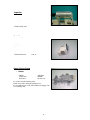
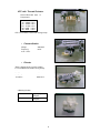
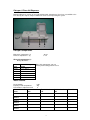
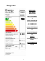
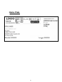
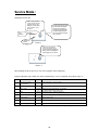
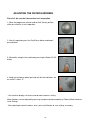
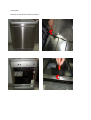
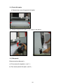
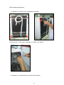
DISHWASHER
SERVICE MANUAL
INDEX
page
Tecnical features and security systems
1
Electrical components
2
Energy Label
8
Name Plate
9
Service mode
10
Failure Codes
11
Adjusting the water hardness
15
Disassembly
18
Repair Techniques
53
Tecnical Features
Security Systems
• Flowmeter:
The amount of water intake is in precise control.
• Heater safety protection:
In case of lack of water, with the help of a pressure switch, the resistance is prevented from
being in operation. So both the resistance and the machine itself are protected.
• Overflow and Leakage Protection:
The dishwasher enters overflow mode when there is too much water in the dishwasher, the
excess water gets drained. (a floater rises upwards and senses when overflow water gets
there)
It also detects leaks in the base of the dishwasher, shuts down operation and automatically
pumps out water before contact with floor.
Resettable overflow
1
Electrical Components
Button ( On / Off Switch )
Buton is assembled in the control panel unit.
On / Off ( two pole )
Voltage
Currency
250 V
16 ( 4 ) A
Door Lock
It is a mechanical lock/release system that is closing the
door, supplying the connection of electrical parts in the
machine and cutting off the connection.
Currency
16 (4) A
Circulation Pump
Voltage
Frequency
Total Power
Coil İsolation Class
Main(First) Coil Ω
Sub(second) Coil Ω
Thermal Protector
Pump Outlet Pressure
Pump Flowrate
220/240 V
50 Hz
88 W
F
95%± 7 Ω
126%± 7 Ω
109 °C
300 mbar
60 lt/min
Single direction, single phase, asynchronous and two
pole.
It turns opposite clock direction.
It is assembled to the basement with rubber hangers.
2
Capacitor
2,5 µ F – 450 V
class P2
Capacitor is permanently connected to the
circulation pump coils.
Drain Pump
Voltage
Frequency
Total Power
Flowrate
Coil Resistance
Coil İsolation Class
Thermal Protection
220/240 Volt
50 Hz
30 W
17 – 21 lt/min
143 Ω %± 7
F
120 ° C
Heater Casing Group
•
Heater
Voltage
Total Power
Resistance
220/240 V
2000 W
23.19 Ω ± ٪5
It is used to heat the washing water.
Heater is not active during the drying process.
It is assembled to the sump and located to the Supply side
of circulation pump.
3
NTC with Thermal Protector
Thermal Protection 83±3 ° C
Temperatures
25°- 5000Ω
35°- 3300Ω
55°- 1520Ω
63°- 1174Ω
80°- 670Ω
90°- 488Ω
%±5.0
%±5.5
%±6.5
%±7.5
%±8.0
%±8.5
NTC is assembled on the heater Casing Group.
•
Pressure Switch
Voltage
Frequency
16 A – 3 Pins
•
220/240 V
50 Hz
Diverter
There is diverter at C31 and C41 models
It is assembled to the heater Casing Group.
Voltage
Frequency
Power
Resistance
220/240 V
50 Hz
8W
6840±٪5 Ω
2 Washing Position
1.Position
2.Position
Upper spray arm
complete
Lower spray arm
complete
4
Water Inlet Valve
Single inlet and single outlet standard single
coil selenoid valve.
Voltage
Frequency
Total Power
Flowrate
Coil İsolation Class
Resistance
220/240 Volt
50-60 Hz
6W
2.5 lt/min
F
3750±٪10 Ω ( 20 Cº )
It is assembled to the basement and connect to the
airbreak by hose.
Regeneration Valve
Voltage
Frequency
Total Power
Resistance
220/240 V
50/60 Hz
6W
4130±٪10 Ω ( 25 Cº )
Regeneration valve is assembled on the water softener.
Parasite Filter
220/240 V
Voltage
Frequency
50/60 Hz
0,1 uF (X1) + 2x0,027uF(Y2) + 1M Ω
It is used to prevent parasites from the main supply. It has
been assemblied to basement.
Turbo Fan Motor
There is a thermal protector.Shaded pole motor , two pole
temperature is between -40–150 Cº .
There is Turbo Fan Motor only at C4 models.
5
Salt Sensor
Voltage
Currency
250 V
50 mA
It is assembled to the water softener.
It warns if the salt is less than requested quantity.
Power Cord
Type
İsolation
Plug
Length
2
Euro 3’lü 1 mm , copper conducting
TS 9760 H05VV-F
TS-IEC 60884–1 PVC injected
1800 mm
Drain Hose
Drain hose maximum height
Drain hose minimum height
Drain hose maximum length
110cm
50cm
400cm
15 W
Total Power
Voltage
Frequency
Resistance
220/240 V
50 Hz.
238.6± ٪ 5 Ω
Coil isolation class:
H
6
Detergent / Rinse Aid Dispanser
Detergant dispenser consists of rinse aid and detergant compartment. It has been assemblied to the
inner door by the snap fits. Only one bobbin has been used for operating the system.
1
2
3
Detergant compartment
Main wash compartment (3)
Prewash compartment (2)
40 cm³
5 cm³
Rinse aid compartment (1) :
Dosage Quantities:
Level
Level 1
Level 2
Level 3
Level 4
Level 5
Level 6
Rinse aid dosage
amount
1 cc ± 0,5 cc
2 cc ± 0,5 cc
3 cc ± 20%
4 cc ± 20%
5 cc ± 20%
6 cc ± 20%
Rinse aid compartmnet: 150 cm³
Factory outlet setting position: level 3
Water Softener
Resin Quantity
Capacity of salt compartment
Total hardness adjustment level
Water
Level
Level 1
Level 2
Level 3
Level 4
Level 5
Level 6
Hardness
0,6lt
2kg
6
German Hardness
°dH
French hardness
°dF
Bristish hardness
°dE
Water Liter
0-5
0-9
0-6
-
6-11
10-20
7-14
160lt
12-17
21-30
15-21
89lt
18-22
31-40
22-28
59lt
23-31
41-55
29-39
46lt
32-50
56-90
40-63
16lt
7
Energy Label
ENERGY LABEL
LOGO :XXXXXX
MODEL:XXXXXX
ENEGY PERFORMANCE
A
ENERGY CONSUMPTION
A ---- 1,05 kWh / cycle
B ---- 1,20 kWh / cycle
WASHING PERFORMANCE
A,B
DRYING PERFORMANCE
A,B
CAPACITY
Standard place settings 12
persons
WATER CONSUMPTION
13 – 15 lt
8
Name Plate
9
Service Mode :
Starting the service test
1-Move the programme
selector knob to the first
program and press the
start/pause button while
your machine is not in
operation
2-Keep the start/pause button
pressed down meanwhile
energise the machine by
pressing the On/Off button
3-Keep start/pause button
pressed until flow indicators
are on and off
Flow
Indicator
Start/pause
button
button
Picture 1
4- Move the programme
selector knob to the reset
position Keep the start/pause
button pressed until program
monitor lights are on and off.
Picture 2
After finalizing the above processes; the service program starts automaticly.
Program algrorithm steps follow each other automatically. In case of a problem; the program stops on
STEP
PROCESS
TIME
CONTROL
0
Show the last failure
occured before
~6 sec
At the beginning of service program
1
Drain
~4 sec
Drain pump is running
2
Fill (~3,5lt)
3
wash
4
Wash + Heating
5
Regeneration
~1 min
Regeneration value
6
Drain
~20 sec
Drain Pump
7
End led highlight
~1min 25
sec
~1min 10
sec
~5 min
Water inlet valve and flowmeter is controlled.
(At 2,5lt circulation pump starts to run)
Circulation pump – detergant dispenser
Heater Casing (pressure switch)- NTC- diverter positions
the problem step and show failure code. You can understand the problem by looking the failure code.
10
Failure Codes : C1 Models
Wash
ERROR CODE
End
Start
/Pause
ERROR
DESCRIPTION
POSSİBLE PROBLEMS
•
Inadequate
water supply
•
•
•
•
•
•
•
•
Error of
continuous water
input
The waste water
in the machine
cannot be
discharged.
Circulation pump can be out of order or have a problem
with the cable connection.
•
Electronic card can be out of order.
•
Water inlet valve can be out of order or can not be
closed.
•
Electronic card can be out of order.
•
•
•
Water outlet hose is clogged.
Water discharge hose can be out of order.
There can be a problem with cable connection of the drain
pump.
Pressure switch of the heater casing group can have a
mechanical or cable connection problem.
•
Intended water
temperature
could not be
reached/ faulty
heater and/or
heater sensor
Make sure the water input tap is totally open and that there
is no water cut.
Close the water input tap, separate the water input hose
from the tap and clean the filter at the connection end of
the hose.
.Water inlet valve filter can be
Water inlet valve can be out of order
There can be a problem with the cable connection of water
inlet valve.
Floater switch can be out of order or have a problem with
the cable connection.
Pressure switch of the heater casing group can have a
mechanical or cable connection problem.
•
Electronic card can be out of order.
•
•
NTC can be out of order.
Faulty NTC cable connection can be faulty. NTCshort or
open circuit.
Thermal protection can be out of order.
Heater can be out of order or cable connection can be out
order.
•
•
•
•
There can be a water leakage from the tub.
Floater switch can be out of order or have a problem with
the cable connection.
•
Electronic card can be out of order.
•
By the Immediate and continuous voltage decreases
software variants can not be kept in the memory of
electronic card.
Faulty
Flowmeter
•
•
Cable connection of flowmeter can be faulty.
Electronic card can be out of order.
Door is open
•
•
Door lock mechanism can be out order.
There can be o problem with the cable connection of door
lock.
Electronic card can be out of order.
Alarm is active
against water
overflow
Electronic card
parameter faulty
•
11
Failure Codes: C2 – C3 – C4 Models
ERROR
DESCRIPTION
ERROR CODE
DISPLAY
WASH
RINSE
DRY
END
CONTROL
START/PAUSE
•
•
•
•
•
Inadequate water
supply
•
•
F5
•
•
Error of continuous
water input
F3
•
•
•
•
•
F2
The waste water in
the machine cannot
be discharged.
•
•
12
Make sure the water input
tap is totally open and that
there is no water cut.
Close the water input tap,
separate the water input
hose from the tap and clean
the filter at the connection
end of the hose.
.Water inlet valve filter can
be
Water inlet valve can be out
of order
There can be a problem with
the cable connection of water
inlet valve.
Floater switch can be out of
order or have a problem with
the cable connection.
Pressure switch of the heater
casing group can have a
mechanical or cable
connection problem.
Circulation pump can be out
of order or have a problem
with the cable connection.
Electronic card can be out of
order.
Water inlet valve can be out
of order or can not be closed.
Electronic card can be out of
order.
Water outlet hose is clogged.
Water discharge hose can be
out of order.
There can be a problem with
cable connection of the drain
pump.
Pressure switch of the heater
casing group can have a
mechanical or cable
connection problem.
Electronic card can be out of
order.
ERROR CODE
DISPLAY
WASH
RINSE
DRY
ERROR DESCRIPTION
END
CONTROL
START/PAUSE
•
•
•
F8
Heater Error: Inadequate
heat
Alarm is active against water
overflow
F1
Alarm is active against water
leakage
F7
Exceed heating problem
(water inside the machine is
too high)
•
NTC can be out of order.
Faulty NTC cable connection
can be faulty. NTCshort or
open circuit.
Thermal protection can be out
of order.
Heater can be out of order or
cable connection can be out
order.
•
Floater switch can be out of
order or have a problem with
the cable connection.
•
Electronic card can be out of
order.
•
There can be a water leakage
from the tub.
•
Floater switch can be out of
order or have a problem with
the cable connection.
•
Electronic card can be out of
order.
•
water inside the machine is
>77°C, NTC can be out of
order.
Electronic card can be out of
order.
•
•
•
•
F9
Diverter position problem
13
•
Diverter electric contacts can
have open circuit
Cable connection of tghe
diverter can be faulty
Electronic card can be out of
order.
ERROR
DESCRIPTION
ERROR CODE
DISPLAY
WASH
RINSE
DRY
END
CONTROL
START/PAUSE
•
•
F6
FE
NTC faulty
•
•
By the Immediate and continuous voltage
decreases software variants can not be
kept in the memory of electronic card
•
Water Hardness is not be adjusted or
Water Hardness adjustment can not be
kept in the elctronic card memory.
Water Hardness shoul be adjusted by
controlling the supply water.
Electronic card
parameter faulty
•
SE
Electronic card water
hardness faulty
•
•
F4
FA
NTC can be out of order.
Faulty NTC cable connection can be
faulty. NTCshort or open circuit.
Electronic card can be out of order.
Cable connection of flowmeter can be
faulty.
Electronic card can be out of order.
Faulty Flowmeter
Faulty turbidity
sensor
•
•
•
•
•
•
•
Door is open
14
Kirlilik sensörü kablo bağlantısı hatalı
Turbidity sensor can be out of order.
There can be some soil around the
turbidity sensor.
Electronic card can be out of order.
Door lock mechanism can be out order.
There can be o problem with the cable
connection of door lock.
Electronic card can be out of order.
ADJUSTING THE WATER HARDNESS
First of all be sure that the machine isn’t in operation
1- Move the programme selector knob to the 0 (Reset) position
while your machine is not in operation.
2- After this operation press the Start/Pause button and keep it
pressed down
3- Meanwhile, energise the machine by pressing the Power On/Off
button
4- Keep the start/pause button pressed until the flow indicators are
on and off. It takes ~5"
- Your machine displays the latest entered water hardness setting.
Water hardness can be adjusted by pressing start/pause button according to Table of Water Hardness
Level Settings.
- After adjusting the water hardness level , press on/off button to save settings in memory.
15
Model : C1
Models C2 – C3
Water
Hardness
Level
German
Hardness
dH
French
Hardness
dF
British
Hardness
dE
Water Hardness Level Indicator
1
0-5
0-9
0-6
2
6-11
10-20
7-14
3
12-17
21-30
15-21
4
18-22
31-40
22-28
End light (12h) is open.
5
23-31
41-55
29-39
Wash and end light (3h+12h) is open.
6
32-50
56-90
40-63
Rinse and end light (6h+12h) is open.
Wash light (3h) is open.
Rinse light (6h) is open.
Dry light (9h) is open.
16
Model C4
Water hardness can be adjusted by pressing “+” and “-“ on display. 3
according to Table of Water Hardness Level Settings.
Water
hardness
level
German
hardness dH
French
hardness dF
British
hardness dE
Hardness Level Indicator
1
0-5
0-9
0-6
L1 is seen on display.
2
6-11
10-20
7-14
L2 is seen on display.
3
12-17
21-30
15-21
L3 is seen on display.
4
18-22
31-40
22-28
L4 is seen on display.
5
23-31
41-55
29-39
L5 is seen on display.
6
32-50
56-90
40-63
L6 is seen on display.
17
DISASSEMBLY
1 ) ACCESSIBILITY
1.1) Top Plate
a) Remove two screws that fix the top plate at the back.
b) Push the top-plate back and pull it up.
18
1.2 ) Front Panel
a) Remove six screws that fix the .front panel.
b).Pull down the front panel as it shown in the Picture.
19
Front panel
Remove six screws that fix the.front panel.
1.3 ) Plastic Kick plate
a) Remove two screws fixing plastic kick plate.
b) Remove the plastic kick plate as it is shown in the picture.
1.4 ) Side panels
Before removing side panels ;
a) Firstly remove the top plate. ( see1.1 )
b) Than remove plastic kick plate. (see1.3 )
20
While removing side panels ;
a) Remove six screws that fix side panels at the back.
b) Remove four screw covers carefully as it shown in the Picture.
b) Remove six screws whice are in front of the machine.
21
22
c) To remove the side panel , remove the upper plastic hinge and than the above
one and pull it up.
1.5 ) Kick Plate Sheet Iron
a) Remove top plate, plastic kick plate and side panels. ( see 1.1 ,1.3 , 1.4 )
b) Remove two screws tat fix the kick plate sheet iron.
c) pull it down as shown in the picture.
23
1.6 ) Control Panel
a)Remove six screws that fix control panlel to the door inside sheet iron.
24
b) Remove the cable connection plastic which fix cable harness to the control panel as shown
in the Picture.
14
c) Remove the conrol panel group carefully as shown in the picture.
d)Remove the wires that are connected to control panel group.
25
1.6.1 ) Rotary Switch
a) Remove the control panel.( see 1.6 )
b)Remove the wire that is connected to the electronic
card.
c) Remove two screws fixing to the control panel group.
1.6.2 ) Electronic Card
a)Remove the wires that are shown in the picture. .
WARNING: while removing wires , do not pull them from wires , pull from connectors.
b)Remove pcb box cover with pulling its plastic hinges.
26
c) Remove the wire which is between rotary switch and electronic card.
d) Remove the electronic card from pcb box by removing pcb box’s plastic hinges.
1.6.3 Display Card ( Only for C4 models )
a) Remove the wire that is between display
card and electronic card.
b) Remove display card from display card
box’s hinge carefully.
27
1.7 )Door Lock Group
a) Remove control panel group. ( see 1.6)
b) Remove two screws that fix the door lock
group.
1.8 ) Dispanser
a) Remove the front panel ( see 1.2 )
b) Remove the wire.
c) Remove dispanser from inside door‘s
hinges by using slotted screwdriwer.
d) Push and remove the dispanser .
Warning : use work glovers otherwise İnside door iron sheet can cut your
hands.
1.9 ) Door Inside
a) Remove side panels. (see 1.4 )
28
b) Remove hinge spring from hinge cord group as it is shown in the picture.
d) Pull the door inside up as it is shown in the picture..
e) remove two screws that fix hinge movement sheet iron to the door inside.
29
THE INNER COMPONENTS
2. ) To Access The Components From Sides
a)Right Sight
b)Left Sight
2.1 Steam Condenser ( only in the models that have active or turbo drying systems )
a)Remove right panel.
b)Open the door , and remove steam condenser’s nut.
c) Pull steam condenser.
30
2.2 ) NTC with Thermal Protector
a) Remove right side panel.(see 1.4)
b) Remove the wires as it is shown in the Picture.
c) Pull the pim down as it is shown in the picture.
31
00
d) Remove the NTC as it is shown in the picture.
2.3 ) Air-Break
a) Remove the left side panel of the
machine.. (see 1.4 )
b) open machine’s door..
c)Rotate counterclockwise air-break nut
and remove it.
d) Remove air –break’s connections with salt cap
as it is shown in the picture.( be careful about
plastic hinges )
32
2.4 ) Hose Connection Plastic
a ) Remove left side panel. ( see 1.4 )
b)By using flat tip screwdriver remove
hose connection plastic’s hinge from the
basement as it shown in the picture.
c)push the hose connection plastic.
Warning : If you do not obey instructions while disassembly of the hose connection
plastic it can be broken.
33
2.5 ) Power Cord
a ) Remove hose connection plastic.( see 2.3 )
e) Remove the lower cover.(see )
f) Remove the wires that is between power cord and parasite filter.
e ) Remove the power cord..
34
3. To Access The Components From İn Front Of The Machine
a)Remove Plastic kick plate and .kick plate iron
sheet.(see 1.3 – 1.5 )
.
3.1 ) Regeneration Valve
a)Remove Plastic kick plate and .kick plate
iron sheet.(see 1.3 – 1.5 )
b) Remove the wires..
c) To remove regeneration Value rotate
counterclockwise and pull it as it is shown in
the picture.
35
3.2) Drain Pump
a)Remove Plastic kick plate and .kick plate
iron sheet.(see 1.3 – 1.5 )
b) Remove the wires..
c)To remove the drain pump that fixes to the sump, rotate it in the direction of
counterclockwise and pull .
36
4.To Access The Components from the Lover Cover
a) Lay the appliance on the rear panel.
b) Remove lower cover from the places that are shown in the picture.
Torna
resm
kısım
37
4.1 ) Circulation Pump
a) Lay the appliance on the rear panel. (see 4 )
Ground
connection
b) Remove
the wires .
Electric
connection
c)Remove two clamps that are shown in
the Picture . ( Heater casing – circulation
pump , sump – Circulation pump )
4.2 ) Heater (Heater-Casing Group without diverter ) ( for C1 – C2 models )
a) Remove the machine’s lower cover.
38
b)Remove four screws that fix heater to
the sump.
c) Remove clamp that are shown in the
Picture . ( Heater casing – circulation
pump ,)
c) Remove the wires that are shown in the picture.
4.2 ) Heater (Heater-Casing Group with diverter ) ( for C3 – C4 models )
a) Remove the machine’s lower cower.
39
b)Remove five screws that fix heater to the
sump.
c) Remove clamp that are shown in the
Picture . (Heater casing – circulation pump)
d) Remove the wires that are shown in
the picture.
e) Detach diverter as it is shown in the
picture.
40
4.3 )Water Softener
a)To remove salt cup cover, rotate it in the direction
of counterclockwise. .
b) To remove salt cup nut , rotate it in the direction of
counterclockwise .
c) Remove left side panel (see 1.4)
d) detach the connections which are between water softener and air-break.
e) Remove lower cover.
f)Remove the hose that is between sump and
salt camp.
41
4.4) Parasite Fitler
a) Remove lower cover.
b) Remove one screw fixing parasite filter.
b) Remove wires..
c) Push parasite filter as shown in the
picture..
42
4.5 ) Floater
a) Remove lower cover. (see 6 )
b) Remove two screws that fix floater as it is shown in the picture.
.
b)remove the two floater hoses .
c)Remove the wire that is connected to the floater.
43
4.6 ) Water Inlet valve
a) Remove lower cover.( see 6 )
b) Remove the wire that is connected to the water inlet valve.
c) Remove the clamp that connects water inlet valve and air –break as it is shown in
the picture.
c) To remove water inlet valve pull it back as it is shown in the direction of Picture
then release water inlet valve from the pins that is connected to . and rotate it in the
direction of counterclockwise.
44
4.7 ) Draining Hose
a) Remove the hose connection plastic.. ( see 4.4 )
b) Remove lower cover. ( see 6 )
c) Remove the clamp that fixes draining hose to the sump.
d) Remove draining hose.
45
5 ) Basket Group
5.1 ) Lower Basket
a)Open machine’s door.
b) Pull the basket to yourself.
wheells
5.2) Upper Basket
a)Open machine’s door.
b) Pull the basket to yourself.
46
c) Open Upper basket rail lock front.
d) Pull the basket to yourself and
remove it.
5.3 )Basket Rails
1
2
1- Upper basket rail stoper rear
2- Upper baket wheels
3- Upper basket rail lock front
3
47
6. ) The Components That Are İnside the Tub
6.1 ) Course , Micro and metal filters
a)Open the door.
b)Remove lower basket.
c) to remove microfilter group rotate them in the direction of counterclockwise and
pull them up as it is shown in the Picture.
d)To remove microfilter group ( course
filter and micro filter ) pull them as it is
shown in the picture.
e)to remove the metal filter pull it up as it
shown in the picture.
48
a)To remove the basket rails, open the
door and take out baskets.
b) To remove basket rails release the rail
from upper basket stopper rear.
49
6.2 ) Spray Arm System
1
2
3
4
5
6
7
8
9
10
11
12
13
14
Upper spray arm feding canal
Upper spray arm adjustment link
Upper spray arm adaptor flange
Upper spray arm adaptor gasket
Upper spray arm adaptor cover
Upper spray arm
Upper spray arm nut plastic
Upper spray arm nut
Upper spray arm shaft
Upper spray arm
Lower sparay arm
Spray arm support
Sump seal
Sump
50
a)After removing the lower basket , pull
the spray arm upwards .gripping it by
the central hub.
b)to remove upper spray arm adjustment link pull it
trought yourself as it is shown in the picture.
c) to remove upper spray feeding canal turn left it
than pull it up as it is shown in the picture.
51
6.3 ) Sump
a) Remove any residual water from the sump by suction so that it does not flow into
the tub and the pressure switch tubes , then lay the appliance on the rear panel.
b) Remove lover cover. ( see 6 )
c) From inside tub ,remove the basket and lower spray arm .
d) Remove the microfilter group and metal filter .
c) detach all the hoses (sump – draining hose , circulation pump – sump, sump –
water softener)
f)Remove the four screws that secure the
tumb to the tub.
g) Remove the two screws which secure the
spray arm support to the sump.
h) detach the drain pump and pull the sump
out ,taking care not to damage the tub seal.
52
REPAIR TECHNIQUES
COMPONENTS AND RESISTANCE VALUES
REAL VALUES
COMPONENTS
ON / OFF BUTTON
DOOR SWITCH (KAPI KİLİDİ)
PRESSURE SWITCH
DRAIN PUMP
WATER INLET VALVE
REGENERATION VALVE
SALT SENSOR
HEATER
DETERGENT DISPENSER
CIRCULATION PUMP
0 Ω ON COMPONENT
CN2.9 – CN2.2
CN2.10 – CN2.2
NOTES
ON/OFF BUTTON IS PRESSED
DOOR IS CLOSE
0Ω
0Ω
∞Ω
FULL FILL WATER
NO WATER
CN2.2 – CN2.4
143 Ω % ± 7
CN2.6 – CN 2.9 3750 Ω ± %10 (20Cº)
CN2.10 – CN2.7 4130 Ω ± %10(25 Cº)
CN5.1 – CN5.2
0 Ω WITHOUT SALT
∞ Ω WITH SALT
23.95±15 Ω
MEASURE JUST ON THE ELECTRONIC
CARD
MEASURE JUST ON THE COMPONENT
1660 Ω ± %10 (25 C º)
CN2.3 – CN2.9
MEASURE JUST ON THE COMPONENT
Primary winding
Secondary winding (FROM THE
COMPONENT)
95 ±%7 Ω
126 ±% 7 Ω
CN 3.2
CN 3.1
SET NTC SENSOR
FAN MOTOR
DIVERTER
25°- 5000Ω %±5.0
35°- 3300Ω %±5.5
55°- 1520Ω %±6.5
63°- 1174Ω %±7.5
80°- 670Ω %±8.0
90°- 488Ω %±8.5
CN 2.6 – CN 2.9 238.6 ± % 5
CN 6.1 – CN 2.9 6840 ± % 5
CN 5.3 – CN5.2
0 Ω
∞ Ω
CN2.1 – CN 2.5
CN2.1 – CN 2.4
0 Ω
∞ Ω
RINSE AID SENSOR
FLOATER (MICROSWITCH )
53
RINSE AID OFF
RINSE AID ON
MICROSWİTICH IS INACTİVE (NO
WATER)
MİKROSWITCH IS ACTIVE (THERE İS
WATER )
MEASURING THE COMPONENTS FROM THE
ELECTRONICAL CARD
a)
b)
In order to reach the connections of the electronic card; dismantle the control panel
(Picture a) and probes of the tester should be applied on to the related connectors of
the electronical card; control the values according to the resistance value table.
(picture b)
Precaution : Always remove the plug from the power socket before touching internal
components.
Washing pump:
From the electronical card:
You can just measure the primary winding value from the electronical card.
Resistance value of the primary winding must be 95 Ω on the connectors CN2.3 –
CN2.9
ELECTRONİCAL CARD
YELLOW
PURPLE
CONNECTORS
CONNECTORS SHOULD BE MEASURED
Above sketch show the connectors of the washing pump on the electronical card.
Probes of the tester should be applied on to the related connectors.
54
From the component:
Measurement of the primary
windings of the washing pump
(
Measurement of the secondary
windings of the washing pump
(white cable – blue cable)
Probes of the tester should be applied on to the related connectors as shown on the
pictures
Drain Pump:
From the electronical card:
CN2.2 – CN2.4
143 Ω ± % 7
ELECTRONİCAL CARD
BROWN
RED
CONNECTORS
CONNECTORS SHOULD BE MEASURED
Above sketch show the connectors of the drain pump on the electronical card.
Probes of the tester should be applied on to the related connectors.
55
From the component :
Probes of the tester should be applied on to the related connectors as shown on the
pictures
Water inlet valve:
From the electronical card:
CN2.6 – CN 2.9
3750 Ω ± 10 ( 20 Cº)
ELECTRONİCAL CARD
BLUE
PURPLE
CONNECTOR
CONNECTORS SHOULD BE MEASURED
Above sketch show the connectors of the water inlet valve on the electronical card.
Probes of the tester should be applied on to the related connectors.
From the components :
Probes of the tester should be applied on to the related
connectors as shown on the pictures
56
Heater Casing :
It can’t be measured from the electronical card.
23.95±15 Ω
From the component:
Probes of the tester should be applied on to the related connectors as shown on the
pictures
Detergent dispenser :
It can’t be measured from the electronical card.
1660 Ω ± 10 (25 C º)
Probes of the tester should be applied on to the related connectors as shown on the
pictures
Regeneration valve:
From the electronical card:
CN2.10 – CN2.7
4130 Ω ± 10 (25 C º)
ELECTRONİCAL CARD
Sketch at the side show the
connectors of the regeneration
valve on the electronical card.
Probes of the tester should be
applied on to the related
connectors.
Sketch at the
PINK
.
ORANGE
CONNECTORS
CONNECTORS SHOULD BE MEASURED
57
From the component :
Probes of the tester should be applied on to the related connectors as shown on the
pictures
Pressure switch:
From the electronical card:
CN2.10 – CN2.2
∞ Ω THERE İS WATER
0 Ω THERE ISN’T WATER
ELECTRONİCAL CARD
BROWN
ORANGE
CONNECTORS
CONNECTORS SHOULD BE MEASURED
Above sketch show the connectors of the pressure switch on the electronical card.
Probes of the tester should be applied on to the related connectors.
From the component:
Probes of the tester should be applied on to the related
connectors as shown on the pictures
58
NTC SENSOR:
From the electronical card:
25°-5000Ω-%±5.0
35°-3300Ω-%±5.5
55°-1520Ω-%±6.5
63°-1174Ω-%±7.5
80°- 670Ω -%±8.0
90°- 488Ω -%±8.5
CN 3.1 - CN 3.2
ELECTRONİCAL CARD
RED
BLACK
CONNECTOR
CONNECTORS SHOULD BE MEASURED
.
Above sketch show the connectors of NTC sensor on the electronical card. Probes of
the tester should be applied on to the related connectors.
From the component:
Probes of the tester should be applied on to the related connectors as shown on the
pictures
Diverter :
From the electronical card :
CN6.1 – CN 2.9
6840 Ω-%±5.0
EECTRONİCAL CARD
Sketch at the side show the connectors of
the diverter on the electronical card.
Probes of the tester should be applied on
to the related connectors.
RED
RED
WHITE
CONNECTOR
CONNECTORS SHOULD BE MEASURED
59
From the component :
Probes of the tester should be applied on to the related connectors as shown on the
pictures.
Salt Sensor
0 Ω There is no salt
∞ Ω There is salt.
CN5.1 – CN5.2
Electronic cart
RED
BLACK
RED
connectors
Sketch at the side show the connectors of the
salt sensor on the electronical card. Probes of
the tester should be applied on to the related
connectors.
CONNECTORS SHOULD BE MEASURED
From the component :
.
Salt sensor can also be measured from the water softener
when the salt sensor assemblied on the water softener.
60
ON/OFF BUTTON
When the button pressed
0 Ω
( can not be measured from the electronical card)
Probes of the tester should be applied on to the related connectors as shown on the
pictures.
DOOR SWITCH
From the electronical card
0 Ω ( DOOR İS
CLOSE )
CN2.9 – CN2.2
ELECTRONIC CARD
PURPLE
CONNECTOR
BROWN
KONNEKTÖR
CONNECTORS
SHOULD BE MEASURED
Above sketch show the connectors of the door switch on the electronical card.
From the component :
Probes of the tester should be applied on to the related connectors.
61
FLOATER
CN2.1 – CN 2.5
0 Ω
CN2.1–CN2.4
∞ Ω
(KONUM 1)
(KONUM 2)
MİCROSWITCH IS
INACTIVE (NO WATER)
MİCROSWITCH IS
ACTIVE (WATER )
From the component :
ELEKTRONICAL CARD
WHİTE
BLACK
CONNECTOR
CONNECTORS SHOULD BE MEASURED
Position 1: You can check the floater by controlling the specified value intervals.
ELECTRONİCAL CARD
WHİTE
RED
CONNECTOR
CONNECTORS SHOULD BE MEASURED
CONNECTORS SHOULD BE MEASURED
Position 2: If failure code is occured related with the floater within control the above
values; you can figure out whether leakage occurs or not.
62
FAN MOTOR
From the electronical card :
CN 2.6 – CN 2.9
238.6 ± % 5
RED
WHITE
ELECTRONICAL CARD
RED
CONNECTOR
Sketch at the side show the connectors of
the fan motor on the electronical card.
Probes of the tester should be applied on to
the related connectors.
CONNECTORS SHOULD BE MEASURED
From the component :
RINSE AID SENSOR
From the electronical card :
There isn’t any rinse aid
There is rinse aid
From the component :
BLACK
0 Ω
∞ Ω
WHITE
CN 5.2 – CN 5.3
CONNECTORS SHOULD BE MEASURED
63