1
•^
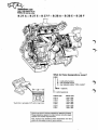
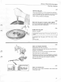
Service Manual
Section 2 (21)
Reconditioning
engine
B 27, B 28
Repairs
and maintenance
260 1975-1983
*#
books4cars.com
4850 37th Avenue South
Seattle, WA 98118 U.SA
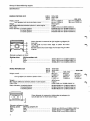
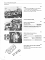
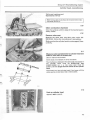
B27A-B27E-B27F-B28A-B28E-B28F
1
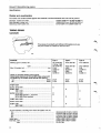
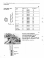
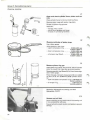
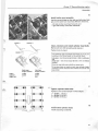
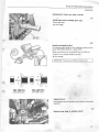
What do these designations mean?
B28E
A = carburetted engine
E = fuel injected engine
F = fuel injected engine "USA models"
28(27) = ce pacity
•
B = petrol (g«jsoline)
The B 28 is in principle a B 27 with a larger bore.
Engine type
Model year
B27A
B28A
1976-1979
1980-1982
B27E
B28E
1975-1980
1981-1983
B27F
B28F
1976-1979
1980-1982
Volvos are sold in versions adapted for different markets.
These adaptions depend on many factors including legal,
taxation and market requirements.
This manual may therefore show illustrations and text
which do not apply to cars in your country.
1
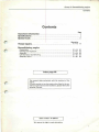
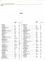
Group 21 Reconditioning
engine
Contents
Contents
Page
... 2
Important information
Specifications
Special tools
... 2
.. 11
Operation
A 1-14 14
Thread repairs
r
Reconditioning engine
Disassembly
Cleaning and inspection
Assembly
Cylinder head, reconditioning
Assembly (cont.)
B 1-19
C 1-41
D 1-35
E 1-26
F 1-33
Index page 62
r
This manual deals exclusively with the overhaul of the
engine.
For work carried out on the engine when fitted in the car,
and for engine removal and installation, please refer to the
separate manuals.
r
Order number: TP 30447/1
We reserve the right to make alterations.
20
26
38
46
52
Group 21 Reconditioning
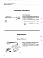
Important
engine
information
Important information
Tightening torques
Nearly all of the B 27/28 engine is made of aluminium
alloy. The threads are tapped directly into the alloy. For
this reason it is extremely important that all of the bolts
are tightened to specified torque.
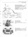
Two types of tightening torques are used in this manual:
I. Tightening torque 40 Nm (30 ftlbs) = a torque
wrench must be used.
II.
Tightening torque 40 Nm (30 ft.lbs) = correct value,
however it is not necessary to use a torque
wrench.
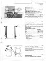
Specifications
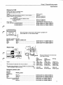
Group 20 General
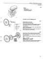
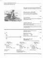
Engine serial number and part number
Located on a plate in front of the oil filter.
On B 28 E/F 1981- models: located on the rear of the
right-hand cylinder head, shows the last three digits of
the part number.
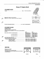
Group 21 Reconditioning
engine
Specifications
Group 21 Engine block
CYLINDER HEAD
New - 111.07 mm (4.373 in)
Height
Max. warp is 0.05 mm over 100 mm.
NOTE! Do not level a warped cylinder head, replace it.
f^
Cylinder head gasket thickness
1.14-1.50 mm (0.045-0.059 in)
CYLINDER BLOCK
Cylinder liners
Pistons and liners are matched sets.
Cylinder liners are marked by 1, 2 or 3 cuts in the upper edge of
the liner.
B 27
B 27
88.00-88.01 mm
91.00-91.01 mm
(3.4646-3.4650 in)
(3.5826-3.5830 in)
88.01-88.02 mm
91.01-91.02 mm
(3.4650-3.4654 in)
(3.5830-3.5835 in)
88.02-88.03 mm
91.02-91.03 m m
(3.4654-3.4657 in)
(3.5835-3.5838 in)
0.16-0.23 mm (0.0063-0.009 in)
Bore, liners marked 1 (A-marked piston)
2 (B-marked piston)
3 (C-marked piston)
Liner height above block face
Shims for adjustment of liner height:
thickness, blue paint marking
white paint marking
red paint marking
yellow paint marking
0.070-0.105
0.085-0.120
0.105-0.140
0.130-0.165
mm
mm
mm
mm
(0.0027-0.0041
(0.0033-0.0047
(0.0041-0.0055
(0.0051-0.0064
in)
in)
in)
in)
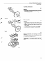
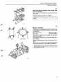
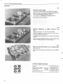
PISTONS
Pistons for B 27
Pistons and liners are matched sets.
Two different manufacturers supply pistons, see next page
for specifications.
f
\
Demolin
Mahle
Group 21 Reconditioning
engine
Specifications
DEMOLIN PISTONS (B 27)
B 27 A
B27E
B 27 F
Height, overall
from gudgeon pin centre to piston crown
Weight
Max weight difference between pistons in same engine
Piston float
Piston diameter, A-marked pistons
B-marked pistons
C-marked pistons
1976-1979
1975-1978
1979
1976-1978
74 mm (2.9134 in)
63.4 mm (2.9960 in)
40 mm (1.5748 in)
39.4 mm (1.5512 in)
445±3 gram
6 gram
0.090-0.110 mm (0.0035-0.0043 in)
87.900-87.910 mm (3.4606-3.4610 in)
87.910-87.920 mm (3.4610-3.4614 in)
87.920-87.930 mm (3.4614-3.4618 in)
Piston diameter is measured at right angles to gudgeon pin
bore and:
11 mm (0.43 in) from lower edge of piston for B 2 7 F
1976-1978
8.5 mm (0.33 in) from lower edge of oil scraper ring for other
engines.
Diameter, gudgeon pin bore:
Marking piston
1
2
3
Marking gudgeon pin
Blue
White
Red
MAHLE PISTONS (B 27)
23.514-23.517 mm (0.9257-0.9259 in)
23.511-23.514 mm (0.9256-0.9257 in)
23.508-23.511 mm (0.9255-0.9256 in)
B 27 A
B 27 E
B27F
Height, overall
from gudgeon pin centre to piston crown
1976-1979
1975-1978
1979
63,4 mm
(2.4960 in)
39.4 mm
(1.5521 in)
1979-1980
1976-1978
62.2 mm
(2.4488 in)
38.2 mm
(1.5039 in)
65.3 mm
(2.5709 in)
41.3 mm
(1.6260 in)
Weight
Max weight difference between pistons in same engine
Piston float
445±3 gram
6 gram
0.020-0.040 mm (0.0008-0.0016 in)
Piston diameter, A-marked pistons
B-marked pistons
C-marked pistons
87.970-87.980 mm (3.4634-3.4638 in)
87.980-87.990 mm (3.4638-3.4642 in)
87.990-88.000 mm (3.4642-3.4646 in)
D
Piston diameter is measured at right-angles to gudgeon pin
bore, 8 mm (0.31 in) from bottom edge.
-ts.
Diameter, gudgeon
Marking, piston
Blue
White
Red
4
pin bore:
Marking, gudgeon pin
Blue
White
Red
23.510 mm-23.513 mm (0.9255-0.9257 in)
23.507-23.510 mm (0.9254-0.9255 in)
23.504-23.507 mm (0.9253-0.9254 in)
Group 21 Reconditioning
engine
Specifications
Pistons for B 28
Pistons and liners are matched sets.
Only Mahle pistons are in use.
Weight
Max weight difference between pistons in same engine
Height, overall A- and F-engines
E-engine
from gudgeon pin centre to piston crown
A- and F-engines
E-engine
Piston float
Piston diameter, A-marked pistons
B-marked pistons
C-marked pistons
455±3 grams
6 grams
62.8 mm (2.4724 in)
65.3 mm (2.5709 in)
38.8 mm (1.5276 in)
41.3 mm (1.6260 in)
0.020-0.040 mm (0.0007-0.0015 in)
90.970-90.980 mm (3.5814-3.5818 in)
90.980-90.990 mm (3.5818-3.5822 in)
90.990-91.000 mm (3.5822-3.5826 in)
Piston diameter is measured at right-angles to gudgeon pin
bore, 8 mm (0.31 in) from bottom edge.
Diameter, gudgeon
Marking, piston
Blue
White
Red
pin bore:
Marking, gudgeon pin
Blue
White
Red
23.510-23.513 mm (0.9255-0.9257 in)
23.507-23.510 mm (0.9254-0.9255 in)
23.504-23.507 mm (0.9253-0.9254 in)
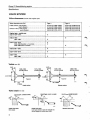
Piston rings
15 mm
Height.
mm
in
Side clearance (measured with ring on piston)
mm
in
3)
Ring gap when checked in 91 mm (3.5826 in) cylinder (B 28),
88 mm (3.4646 in) (B 27), see fig
mm
in
Ring gap measured 15 mm (0.6 in) from
lower edge of cylinder
Upper
compression
ring
1.478-1.490
9.0582-0.0587
0.045-0.074
0.0017-0.0029
Lower
compression
ring
1.978-1.990
0.0779-0.0783
0.025-0.054
0.0009-0.0212
2.629-2.731
0.1035-0.1075
0.009-0.233
0.0003-0.0091
0.40-0.60
0.0157-0.0236
0.40-0.60
0.0157-0.0236
0.38-1.45
0.0150-0.0570
Oil ring
Gudgeon (piston) pins
Diameter
Marking,
Marking, piston
gudgeon pin
Blue
Blue (1)
White
White (2)
Red
Red (3)
Clearance in connecting rod
piston, Mahle
Demolin
23.500-23.497 mm (0.9251-0.9250 in)
23.497-23.494 mm (0.9250-0.9249 in)
23.494-23.491 mm (0.9249-0.9248 in)
0.020-0.041 mm (0.0007-0.0016 in)
0.010-0.016 mm (0.0003-0.0006 in)
0.014-0.020 mm (0.0006-0.0008 in)
Group 21 Reconditioning engine
Specifications
VALVE SYSTEM
Valve Clearances (varies with engine type)
Valve clearance mm (in)
Type 1
Type 2
Intake valves, cold engine
warm engine
Exhaust valve, cold engine
warm engine
0.10-0.15 (0.004-0.006)
0.15-0.20(0.006-0.008)
0.25-0.30 (0.010-0.012)
0.30-0.35 (0.012-0.014)
0.20-0.25 (0.008-0.010)
0.25-0.30 (0.010-0.012)
0.30-0.35 (0.012-0.014)
0.35-0.40(0.014-0.016)
Engine type - model year
B 27 A 1976-1979
X
B 28 A 1980
1981-1982
X
X
B27 E 1975-1978
1979-1980 Sweden + Australia
1979-1980 Other markets
X
X
B28 E1981-1983
X
B 27 F1976-1979
X
B 28 F1980
1981-1982
X
X
X
Valves mm (in)
44.5'
29,5°
£
7.965-7.980
(0.3135-0.3141)
^
59"
44(1.7322)
Tapered
7.965-7.980
(0.3135-0.3141)
7.975-7.990
(0.3139-0.3145)
iT
37
(1.4566)
32 (1.2598)'
26.5
(1.0433)
Intake valves
Exhaust valves
Valve seats mm (in)
1.7-2.1 mm (0.0669-0.0826)
Intake valve seat
Early types
1.3-1.7 mm (0.0511-0.0669)
Intake valve seat
Late types (venturi seat):15° and 60° are
correct angles to reduce seat width.
2.0-2.4 mm (0.0787-0.0944)
Exhaust valve seat
Group 21 Reconditioning
engine
Specifications
Note! When replacing valve seats: the interference between
the valve seat and its bore in the cylinder head must be
0.070-0.134 mm, (0.0027-0.0052 in), i.e. the valve seat diameter must be 0.070-0.134 mm greater than the diameter of the
bore in the cylinder head.
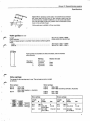
Valve seats are available in three oversizes.
Valve guides mm (in)
Length
Inner diameter
Press-in measurement to cylinder head contact surface against
block:
intake
exhaust
50.1-51.3 (1.2725-1.3030)
8.000-8.022 (0.3149-0.3158)
39.5-40.5 (1.5551-1.5944)
36.9-37.9 (1.4527-1.4921)
Valve guides are available in three oversizes, and are marked
with grooves.
Standard
Oversize 1
2
3
Marking
Reamer for seat
No groove
1 groove
2 grooves
3 grooves
5166
5167
5168
/"*
Valve springs
Two types of valve springs are in use. The springs are colour coded
as follows:
Grey springs:
Green springs:
B27A
B27E
B28A
B 27 E
1980-1982
1979-1980 (excluding Sweden, Australia)
B28E
B28F
1981-1982
1980-1982
B27F
1976-1979
1975-1978
1979-1980 Sweden + Australia
1976-1979
Grey springs:
Length
mm
in
47.2
40.0
1.86
1.57
32.2
1.27
Green springs:
Load
N(kp)
0
233-268
(23.3-26.8)
521-585
(52.1-58.5)
lbs.
Length
mm
in
Load
N(kp)
lbs.
0
52-60
47.1
40.0
1.85
1.57
0
23.0-26.6
0
51-59
116-131
30.0
1.18
613-689
(61.3-68.9)
137-154
Group 21 Reconditioning
engine
Specifications
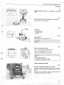
Rocker arm mechanism
The rocker arm contact surface against the camshaft is surface-hardened and must not be ground.
Diameter, rocker arm shaft
Hole diameter, rocker arm
Clearance, shaft-rocker arm
19.959-19.980 mm (0.7857-0.7866 in)
19.992-20.013 mm (0.7870-0.7879 in)
0.012-0.054 mm (0.0005-0.0021 in)
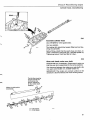
TIMING GEARS
Camshaft
Three types of camshafts with different lift heights are in use.
The part number is marked on the front end.
Camshaft
Type 1
Type 2
Type 3
Marking (part number), left
7910 245 522
(-143 or -144)
7910 245 412
5.144
(0.202 in)
5.059
(0.199 in)
74 01 269138
74 01 269 615
74 01269 139
6.004
(0.236 in)
6.004
(0.236 in)
74 01 269 616
5.96
(0.234 in)
5.96
(0.234 in)
9°±3°
7°±3°
9°±3°
9°±3°
8°±3°
8°±3°
right.
Max. lift height, left
right
mm
mm
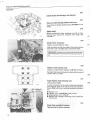
Check of camshaft setting (cold engine):
Adjust valve clearance on 1st and 6th intake valves to 0.7
mm (0,027 in), the intake valves should then open at,
1st
BTDC
6th
BTDC
Engine type
B27 A 1976-1979
B28 A 1980
1981-1982
B27E1975-1978
1979-1980 Sweden 4- Australia.
1979-1980 Other markets
X
X
B28E1981-1983.
B27F 1976-1979.
B28F1980
1981-1982.
Journal diameter, counting from front (all types): mm (in)
1st
2nd
3rd
4th
Radial play
End float, new
max
40.440-40.465 (1.5921-1.5931)
41.040-41.065 (1.6157-1.6167)
41.640-41.665 (1.6393-1.6403)
42.240-42.265 (1.6629-1.6639)
0.035-0.085 (0.0013-0.0033)
0.070-0.144 (0.0027-0.0056)
0.5 (0.0196)
Group 21 Reconditioning
engine
Specifications
CRANK MECHANISM
Crankshaft
Max run-out (measured on two centre main bearing journals).
Crankshaft, end float
clearance (main bearings)
Crank journals, side clearance
clearance
Rear sealing ring diameter, standard
undersized
0.02 mm
0.070-0.270 mm
0.038-0.088 mm
0.20-0.38 mm
0.030-0.080 mm
79.926-80.000 mm
79.726-79.800 mm
(0.0007 in)
(0.0027-0.0106
(0.0014-0.0034
(0.0078-0.0149
(0.0011-0.0031
(3.1466-3.1496
(3.1388-3.1417
0.007 mm
0.01 mm
70.043-70.062 mm
69.743-69.762 mm
1.961-1.967 mm
2.111-2.117 mm
(0.0002 in)
(0.0003 in)
(2.7575-2.7583 in)
(2.7457-2.7465 in)
(0.0772-0.0774 in)
(0.0831-0.0833 in)
29.20-29.25 mm
29.40-29.45 mm
29.50-29.55 mm
29.60-29.65 mm
2.30-2.35 mm
2.40-2.45 mm
(1.1496-1. 1515 in)
(1.1574-1.1594 in)
(1.1614-1.1633 in)
(1.1653-1.1673 in)
(0.0905-0.0925 in)
(0.0944-0.0964 in)
(0.0964-0.0984 in)
(0.0984-0, 1003 in)
in)
in)
in)
in)
in)
in)
Main bearing journals
r
Out of roundness, max
Taper, max
Diameter, standard
undersized
Main bearing shells, thickness, standard
oversized
Width of crankshaft journal for thrust bearing (rear main bearing
journal):
standard
oversized 1
2
3
Thrust bearing washer, thickness, standard
oversized 1
2
3
2.45-2.50 m m
2.50-2.55 m m
rr
Taper
Connecting rod bearing journals
Out of roundness, max
Taper, max
Diameter, standard
undersized
Connecting rod bearing shells, thickness, standard
undersized
Bearing journal width
Out of roundness
0.007 mm
0.01 mm
52.267-52.286 mm
51.967-51.986 mm
1.842-1.848 mm
1.992-1.998 mm
39.99-40.09 mm
(0.0002 in)
(0.0003 in)
(2.0577-2.0585
(2.0456-2.0466
(0.0725-0.0727
(0.0784-0.0788
(1.5744-1.5783
0.20-0.38 mm
146.15 mm
±2.5 grams
(0.0078-0.0149 in)
(5.7539 in)
0.05 mm
0.15 mm
(0.0019 in)
(0.0059 in)
in)
in)
in)
in)
in)
Connecting rods
End float on crankshaft (both con rods fitted)
Length between centres
Max weight difference between con rods in same engine
Flywheel
Axial throw, max
Radial throw, max (measured at diameter 282.4 mm)
Group 21 Reconditioning engine
Specifications
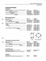
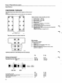
TIGHTENING TORQUES
The tightening torques shown below apply to oiled nuts and
bolts.
Degreased (washed) parts must be oiled prior to assembly.
Tighten all bolts in stages according to below:
1
2
3
4
5
6
7
8
9
10
=
=
=
=
=
=
=
=
=
=
10 Nm (1 kpm = 7 ft. lbs)
30 Nm (3 kpm = 22 ft. lbs)
60 Nm (6 kpm - 44 ft. lbs)
Wait 10-15 minutes
Slacken bolts
15-20 Nm (1.5-2.0 kpm = 11-15 ft. lbs)
Angle-tighten to 113-117°
Warm-up engine to operating temperature
Cool block 30 minutes
Slacken and then retighten bolts one at a time in specified
tightening order.
Retighten according to stages 6 and 7.
Tightening sequence for cylinder head bolts
#
®
Main bearings
Tighten all nuts in stages:
1 = 30 Nm (22 ft. lbs)
= Slacken nut 1
= Tighten nut 1 to 30-35 Nm (22-26 ft. lbs.)
= Angle-tighten nut 1 73°-77°
= Slacken and retighten the other nuts in the order
specified in stages 2-4.
o a
i
i
©
®
©
»
!
Tightening sequence for main bearings (via lower crankcase)
Cylinder head (see below)
Connecting rod bearings
Crankshaft front end, 1975-1977
1978-
Nm
ft. lbs.
45-50
160-180
240-280
33-37
118-133
177-207
Nm
ft. lbs.
70-90
45-50
12±2
15
52-66
33-37
9±1.5
11
40 mm = 1.575 in
45 mm = 1.772 in
1975-1977
1978-
Camshaft sprocket
Flywheel (always use new bolts)
Spark plugs (do not oil)
Valve cover
10
Group 21 Reconditioning
engine
Specifications
Group 22 Lubricating system
OIL PUMP
End float
Radial play between cog tip and pump housing
wall (excl. bearing play)
Backlash (excl. bearing play)
Bearing play, drive shaft
idler shaft
Relief valve spring, length at various loads:
unloaded
loaded to 88.3 N (8.83 kp = 20 lbs)
0.025-0.084 mm (0.0009-0.0033 in)
0.110-0.185 mm (0.0043-0.0072 in)
0.17-0.27 mm (0.0066-0.0106 in)
0.015-0.053 mm (0.0006-0.0021 in)
0.015-0.051 mm (0.0059-0.0020 in)
89.5 mm (3.52 in)
56.5-60.5 mm (2.22-2.33 in)
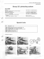
Special tools
999
Description - use
1426-9 Drift: fitting pilot bearing in crankshaft (late type)
1801-3 Standard handle: used with 5101 and 5953
2484-7 Centering drift: clutch, M45/46 gearboxes (early type)
2520-8
4090-0
5029-7
Stand: used with fixture 5099
Extractor: pilot bearing
Drift: fitting intake valve seat
Continued on page 12.
4090
11
Group 21 Reconditioning
engine
Special tools
999
Description - use
5092-5
5093-3
5096-6
Combined tools: (6 parts) removing-fitting gudgeon (piston) pins 5128 and 5129 also required
for Mahle pistons.
Retainer: (4 x) for cylinder liners
Spacer sleeve: main bearings
5098-2
5099-0
5101-4
Protractor: for angle-tightening cylinder head bolts and main bearing nuts
Fixture: for engine. Used with 2520
Drift: fitting pilot bearing in crankshaft (early type). Used with 1801
5103-0
5108-9
5109-7
Drift: fitting crankshaft front oil seal
Drift: fitting valve guide - intake
Drift: fitting valve guide - exhaust
5111-3
5112-1
5113-9
Centering drift: clutch, M45/46 gearboxes (late type)
Locking sector: locking flywheel
Centering drift: clutch, M50/51 gearboxes
5128-7
5129-5
5165-9
Piston support: removing gudgeon pin from Mahle piston. Used with 5092
Piston support: fitting gudgeon pin in Mahle piston. Used with 5092
Reamer kit: valve guides: contains 5164 (early type), 5224 (late type), 5166, 5167 and 5168
5166-7
5167-5
5168-3
Reamer: valve guide seat oversize 1
Reamer: valve guide seat oversize 2
Reamer: valve guide seat oversize 3
5192-3
5218-6
5220-2
Support: for dial indicator. Measuring cylinder liner height and piston height. Also 5094 can be
used
Drift: removing valve guides. Fitting oil seal on valve guide
Drift: fitting valve seat - exhaust
5224-4
5953-8
Reamer: cleaning valve guides. Also 5164 can be used
Drift: fitting crankshaft rear oil seal. Used with 1801
(y) (§)
5128
5092-1
5092
5092-2
5129
IIG3U
5092-3 5092-4 5092-5 5092-6
5093
T
M
E
A
^~-a
L„iffli 1801 + 5101
M | 1426
! •
Wz
^Mm
A i
1
5099
5101
^tor^^^f -•*
z^^^j
Group 21 Reconditioning
engine
Special
5103
5108, 5109
tools
5111
(y) (g)
5128
r
5092-1
5092-2
5129
5092-3 5092-4 5092-5 5092-6
110 214
5112
5113
5128, 5129
n
ggg* # i U
5165 (5166. 5167, 5168)
5192
5218
*
i
5220
5224
5953
13
Group 21 Reconditioning
Thread
engine
repairs
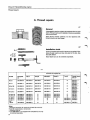
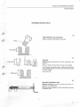
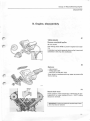
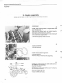
A. Thread repairs
A1
General
A damaged thread can usually be repaired with a thread
insert. Thread inserts and installation tools are available
from Volvo Parts.
Note! Some threads can/may not be repaired with
thread inserts, see next page.
A2
Installation tools
Tools to install thread repair inserts are supplied in kits.
Some thread inserts are also included in the kits. See
the table below.
Note! Each tool can be ordered separately.
Contents of complete kit
Complete
kit
Tap A
Tang B
Mandrel C
Crank D
M6x1
998 5840-9
998 5802-9
998 5803-7
998 5804-5
998 5805-2
4)
M7x1
998 5841-7
998 5806-0
998 5807-8
998 5808-6
998 5809-4
4)
M 8x1.25
998 5842-5
998 5810-2
998 5811-0
998 5812-8
998 5813-6
4)
M 10x1.5
998 5843-3
998 5814-4
998 5815-1
998 5816-9
998 5817-7
4)
M 12x1.5
998 5844-1
998 5818-5
998 5819-3
998 5820-1
998 5821-9
4)
M
M
M
M
M
998 5845-81
998 5846-6
998 5847-4
998 5848-2
998 5849-0
998
998
998
998
998
5823-5
5826-8
5827-6
5831-8
5833-4
2)
2)
2)
2)
2)
998 5824-3
998 5824-3
998 5828-4
3)
3)
998 5825-0
998 5825-0
998 5829-2
3)
3)
4)
4)
4)
998 5832-6
998 5834-2
956014-5
956015-2
948015-3
941843-5
956018-6
956019-4
956022-8
956023-6
948094-8
948095-5
948756-2
948756-2
948758-8
947847-0
947843-9
998 5850-8
998 5860-7
2)
3)
3)
998 5861-5
948755-4
14x1.25
14x1.25
14x1.5
16x1.5
18x1.5
5/8"18UNF
Notes:
Designed especially for spark plug threads (do not drill).
21
Use flat nosed pliers or similar tool.
3)
Supplied with set.
4>
Tool 998 5830-0 is not supplied with complete kit, but may
be ordered separately.
14
11
ToolE
Thread inserts
(10 x) F
Thread
+
+
+
+
+
Group 21 Reconditioning
engine
Thread repairs
A3
Do not repair these threads
(Threads shown below cannot or must not be repaired)
for oil filter
/^-
Connecting rod bearings bolts
Cylinder block
Adjustment screws
Idle adjustment screw
Lower section of air-fuel control unit
B 27 E 1979-, B 28 E, B 27/28 F
Timing gear case
Idle adjustment screw
Intake manifold B27/B28
All conical threads such as plugs and nipples in intake manifold (also B 28/B 28 A)
75
Group 21 Reconditioning
Thread
engine
repairs
A4
Thread repair insert,
drill diameter
0
Thread
Length mm
P/N
M 6x1
9.0
12.0
956014-5
956015-2
6.3
6.3
M7x1
10.5
14.0
948015-3
941843-5
7.3
7.3
M 8x1.25
8.0
11.4
16.0
956017-8
956018-6
956019-4
8.4
8.4
8.4
M 10x1.5
10.0
15.0
20.0
25.0
956021-0
956022-8
956023-6
956024-4
10.5
10.5
10.5
10.5
M 12x1.5
12.0
24.0
30.0
948094-8
948095-5
956028-5
12.5
12.5
12.5
M 14x1.25
14.5
948756-2
14.3
M 14x1.5
10.0
948758-8
14.5
M 16x1.5
12.0
947847-0
16.5
Mx18x1.5
13.5
947843-9
18.5
8.0
948755-4
16.4
5/88"x18UNF
Drill dia mm
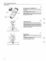
A5
Repairing spark plug threads
Cylinder head must be removed first. Tap hole from inside to avoid damaging seat for spark plug.
Do not drill the hole. Use tap 998 5823-5.
Re-cut old threads only. Do not cut further into
cylinder head. Spark plug bore must not be threaded
along entire length.
Screw in thread insert (P/N 948756-2).
Combination tap
Tap section
Reamer section
Guide
16
Group 21 Reconditioning
Thread
engine
repairs
Installing thread inserts
A6
Select drill size, tap and insert
Measure length and thread of old hole.
Thread
Thread depth
A7
Tap hole
Drilling depth
NOTE! Special instructions for spark plug holes, see
page 16.
Measure depth of hole. Drill out hole to this depth.
Cut the screw thread to such a depth that the thread
insert makes contact with fully cut screw thread along
its entire length.
Clean the hole.
Drilling depth
A8
Assemble installation tool
M6-M14 threads: fit correct mandrel and crank in installation tool 998 5830-0.
M16 and coarser threads: use the prescribed complete
installation tool.
17
Group 27 Reconditioning
engine
Thread repairs
A9
Tang
Crank
Fit thread insert in installation tool
Fit the thread insert in the tool with the tang facing
downwards.
Turn the crank clockwise until the tang of the thread
insert engages the slot in the crank.
Without pressing, screw the thread insert into the
mandrel until the first thread of the insert is flush with
the opening of the mandrel.
Mandrel
AW
Install thread insert
Hold the tool vertically above the centre of the hole.
Without pressing, screw in the thread insert until the
top thread of the insert is at least 1/2 a thread below the
working surface (0.5 x pitch). The insert must not be
screwed in to the bottom otherwise it will not be possible to break off the tang.
AH
Break off tang
M16-M12 threads: use the tang breaker in the installation kit.
M14 and coarser threads: use a pair of flat nosed pliers
to break off the tang downwards.
Remove the tang from the hole.
18
Group 21 Reconditioning
Thread
engine
repairs
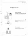
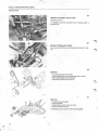
Removing thread repair inserts
A12
File groove in thread insert
Using a triangular file make a groove in the top thread of
the insert, approx. 1/4 of a thread from the end. Take
care not to damage the thread holding the insert.
A13
Remove thread insert
Insert a sharp edge of a triangular scraper in the groove.
Press downwards and rotate anti-clockwise until the insert is removed.
A14
Fit new thread insert
Clean the hole with a tap and fit a new insert.
19
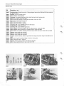
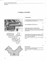
Group 21 Reconditioning
engine
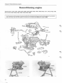
Reconditioning engine
Special tools: 1426, 1801, 2484, 2520, 4090, 5029, 5092, 5093, 5096, 5098, 5099, 5101, 5103, 5108, 5109,
5111, 5112, 5128, 5129, 5165, 5192, 5218, 5220, 5953
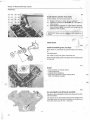
Forthe overhaul of the engine it is presumed that the components shown in the illustration below have already
been removed. Also that the engine is mounted on universal stand 2520 with support 5099.
5099
5099
2520
20
Group 21 Reconditioning
engine
Disassembly
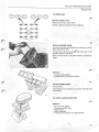
B. Engine, disassembly
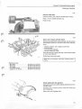
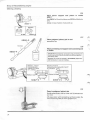
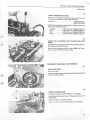
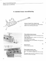
B1
TIMING GEARS
Remove crankshaft pulley
36 mm socket.
Use locking sector 5112 to prevent engine from rotating.
Pulley key must point upwards when pulley is removed
otherwise it will drop into crankcase.
B2
Remove:
- valve covers
- timing gear case
- seal from timing gear case.
Cover holes in crankcase with e.g. paper to prevent dirt
from entering.
B3
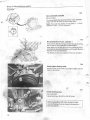
Check chain wear
Check position of belt tensioners. If tensioner pin protrudes by 4 or more notches (8 mm • 0.32") chains
should be renewed.
IMPORTANT! If chains are replaced, sprockets and oil strainers must also be replaced.
21
^
Group 21 Reconditioning
engine
Disassembly
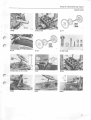
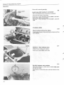
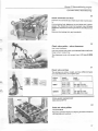
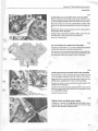
B4
Slacken camshafts centre bolts
Allen key 10 mm.
If necessary prevent sprocket from rotating with a
screwdriver.
B5
Slacken timing gear chains
Turn each lock 1/4 turn anti-clockwise and push in piston.
* >
B6
Remove:
-
oil pump sprocket and chain
chain tensioners and oil strainers (see arrows)
bent and straight chain dampers
camshaft sprockets and chains.
B7
Remove:
-
oil pump with sprocket
outer sprocket
spacer sleeve (early type) and key
inner sprocket and key.
If necessary use a puller to remove sprockets.
22
Group 21 Reconditioning
engine
Disassembly
CYLINDER HEAD
@=s=@
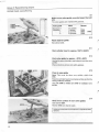
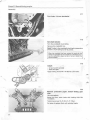
B8
Remove rocker arms
Mark left and right rocker arms.
Slacken bolts in sequence shown adjacent.
3#C^#1
1#C^®3
2(ixrx#4
—U
U
LJ
B9
Remove cylinder heads
Do not lift cylinder head directly up otherwise cylinder
liners may lift as well.
Use two bars (0 12 mm, length 300 mm) and lift off
cylinder head as illustrated.
Place cylinder heads on wooden blocks to prevent damage.
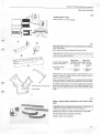
BIO
Remove:
- cylinder head gaskets
- guide sleeves, use a pair of pliers.
B11
Fit liner holders 5093
Two per side.
Liner holders must always be used when cylinder head
is removed.
OIL SUMP, LOWER CRAIMKCASE
B12
Remove:
-
oil sump with gasket
oil strainer with O-ring
splash panel
lower crankcase
O-ring for oil channels and guide sleeve.
23
Group 21 Reconditioning
engine
Disassembly
673
5096
Install:
- main bearing holder 5096 for two outer bearings
- a nut for the two centre main bearings.
This is to prevent the crankshaft/main bearings from
falling out when the engine is turned.
PISTONS, CONNECTING RODS
674
Check con rod side clearance
Use a feeler gauge.
Clearance, new parts
0.20-0.38 mm
(0.008-0.015")
If clearance is too great, con rods must be replaced.
Note that con rods must be replaced in sets.
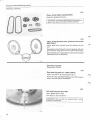
675
Check marking of con rod and cap
If necessary mark as follows:
Cylinder
Marking of con
rod and cap
1 4
early type
late type
Crank webs (from rear)
2
5
3 6
A B C D E F
1
1
2
3
2
4
5 6
3
676
Remove pistons with con rods and bearings
Clean cylinder liners.
Assemble con rod, cap and bearing shells to prevent
interchange of parts.
24
Group 21 Reconditioning
engine
Disassembly
FLYWHEEL, CRANKSHAFT
Automatic
transmission
877
Remove:
- carrier plate. Use locking sector 5112 to lock flywheel
when bolts are removed
- rear sealing flange. Tap out seal from flange.
Automatic
Manual gearbox
g-jg
Remove:
- pressure plate and clutch disc. Slacken pressure plate
bolts crosswise, a few turns at a time to prevent
warp.
- flywheel. Use locking sector 5112 to prevent engine
from rotating
- rear sealing flange. Tap out bearing from flange
- pilot bearing from crankshaft. Use puller 4090.
Manual
B19
Remove crankshaft, main bearings and thrust
bearings
Check marking of bearing caps, mark if necessary. Caps
are marked 1-4, counting from rear.
IMPORTANT! Do not interchange bearing shells and
caps.
25
Group 21 Reconditioning
Cleaning,
engine
checking
C. Cleaning, checking
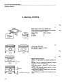
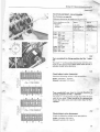
C1
Check type of piston and cylinder liner
Pistons and liners are matched sets, based on diameter.
Three types are available as follows:
Liner, marking
1 notch
2 notches
3 notches
Piston, marking
A
B
C
C2
Check make of pistons
B 27 engines = Demolin or Mahle.
B 28 engines = Mahle.
m~^i
Mahle
Demolin
/^v
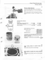
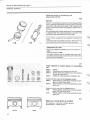
C3
la
Measure piston diameter
7U.
8 mm
to.
Measure at right angles t o gudgeon (piston) pin
bore.
Diameter must be measured at different
depending on make and model year.
Mahle
heights
•
i
•
4
SZZ\
N
26
''
1
^^
f
•*
•
\
Demolin
"
8,5 mm
11 mm(B27F 1976-1978)
II
All Mahle pistons = 8 mm (0.31 in) from lower
edge
• B27F 1976-1978 with Demolin pistons = 11 mm
(0.43 in) from lower edge
• Other Demolin pistons = 8.5 mm (0.33 in) from lower
edge of oil ring groove.
See specifications on pages 4-5 for diameters of new
parts.
Group 21 Reconditioning
engine
Cleaning,
checking
C4
Measure cylinder diameter
Use a dial indicator (50-100 mm = 1.97-3.94 in).
Measure max. wear 30 mm (1.18 in) from block surface.
Measure min. wear at lower turning point of piston.
See specifications on page 3 for diameter of new
parts.
Calculate piston clearance
Example:
Cylinder bore, measured diameter
Piston diameter, measured
Piston clearance
min. 91.010
90.085
max. 91.035
90.985
min. 0.025
max. 0.050
Piston clearance for new parts:
B27 Demolin piston
Mahle piston
B 28 Mahle piston
0.090-0.110 mm
(0.0035-0.0043 in)
0.020-0.040 mm
(0.0008-0.0016 in)
0.020-0.040 mm
(0.0008-0.0016 in)
If clearance is too large replace liners, piston and gudgeon pin. These parts are matched and can only be purchased in kits of six.
Remove liner if piston/liner is to be replaced.
Proceed to
C5
Clean mating surface on cylinder
liner
block and
Use a plastic putty knife to avoid damage.
C6
Mark position of cylinder liner before removing
liner
Mark position and number of each liner. Do not scratch
surface.
27
Group 21 Reconditioning
Cleaning,
engine
checking
C7
Clean and check cylinder liners, piston and con
rods
Clean cylinder bores to remove bright surfaces.
Remove piston rings with piston ring pliers.
Scrape out piston ring grooves.
Check for:
- damage, wear, cracks
- out-of-round gudgeon pin bores
- threads on connecting rod bolts.
C8
Measure axial play of piston rings
Use a feeler gauge.
Axial clearance, new rings:
- upper compression ring
- lower compression ring
- oil scraper ring (fitted)
13S706
0.045-0.074 mm
(0.0018-0.0029 in)
0.025-0.054 mm
(0.0010-0.0021 in)
0.009-0.233 mm
(0.0004-0.0092 in)
C9
Measure piston ring gap
Insert piston ring in bore, one at a time. Use an inverted
piston to ensure that rings take up correct position.
Measure gap with ring 15 mm (0.6 in) from lower edge.
Use a feeler gauge.
Piston ring gap, new parts measured in 88 mm (3.4646
in) (B27) or 91 mm (3.5826 in) (B 28) cylinder diameter:
- upper and lower compression rings. 0.40-0.58 mm
(0.0157-0.0228 in)
- oil scraper ring
0.38-1.43 mm
(0.0150-0.0563 in)
Replacing damaged connecting
Operations
CI0-11
rod
bolt
CIO
Hammer out old bolt
Remove bearing cap and shells. Mount connecting rod
in vice protected by soft jaws.
Tap out boltwith a plastic mallet. Hold piston to prevent
damage.
28
Group 21 Reconditioning
Cleaning,
engine
checking
C11
Press in new bolt
Position bearing cap, observe identification marks.
Place a 12 mm socket beneath cap.
Press in bolt.
r
r
A ^
C12
Clean and inspect cylinder block
Remove all plugs before cleaning block. Do not remove
identification marks for cylinder liners when cleaning.
Clean:
-
sealing surfaces. Use a plastic putty knife
bearing seats
oil and water channels
cylinder head bolt holes.
Check for damage, cracks and wear. Also check threads
on main bearing bolts.
Re-fit plugs using new seals.
Note! Carry out operation C13 before installing block in
fixture.
Tightening torque:
- M12 bolts
- M18 plugs
- M25 plugs
- oil pressure sender
- adapter for oil dipstick
15-20
30-40
40-45
30-40
20-30
Nm (11-15 ft.lbs.)
Nm (22-30 ft.lbs.)
Nm (29-33 ft.lbs.)
Nm (22-30 ft.lbs.)
Nm (15-22 ft.lbs.)
C13
Check guide pins for gearbox
Guide pins must protrude 10-12 mm (0.39-0.47 in) from
cylinder block.
If tubular pins are fitted replace these with solid type
{P/N 1232544-5).
Secure pins with locking fluid.
29
Group 21 Reconditioning
engine
Cleaning, checking
Early type
Late type
C14
Check overflow valve in cylinder block
Two types are in use:
- early type = without filter
- late type = with filter
Early type valves must be replaced with new type.
§WUU
Overflow valve, replacement
Operations CI5-17
C15
Remove old valve and clean seat
Use a screwdriver.
Important! Take care not to damage the oil filter mating
surfaces and make sure that dirt does not enter the oilways.
C16
Install new parts
Install valve with spring facing inwards.
C17
Tap in washer and secure it
Use an 11 mm (inner diameter) socket.
Secure washer by making three notches in block with a
drift.
30
Group 21 Reconditioning
Cleaning,
engine
checking
C18
Clean and check crankshaft, main bearing caps
and main bearings
Clean oilways in crankshaft with a piece of wire and
blow clean.
Also check sealing surfaces on crankshaft.
IMPORTANT! Do not interchange bearing caps and
shells.
C19
UJ
c f\
/T?
'
Taper
Measure crankshaft
Measure out-of-roundness and taper of crank pins. Use
a micrometer and take measurements at several different positions.
Max. out-of-round
Max. taper
0.007 mm (0.0003")
0.01 mm (0.0004")
Crank pins can be ground to a smaller size, see specifications on page 9.
Out-of-round
If crankshaft is thought to be out-of-true check with a
dial indicator.
Support crankshaft by two outer main bearings on a Vblock.
Rotate one turn and measure out-of-true for two centre
crank pins. Out-of-true = max. 0.02 mm (0.0008 in).
IMPORTANT! B 27 E 1975 models may be fitted with early
type crankshafts, see C20.
31
Group 21 Reconditioning
Cleaning,
engine
checking
Replacing piston or connecting
Operations
C20-29
rod
C20
General
Pistons- connecting rods should only be disassembled
when replacing pistons/liners. Once a piston has been
removed it may not be used again. This is because the
piston is deformed when the gudgeon (piston) pin is
removed.
If a connecting rod is to be removed, it is not necessary
to disassemble the piston-connecting rod since new
connecting rods and pistons must be used.
Liner- piston - gudgeon pin are supplied in matched sets
(six).
Connecting rods are supplied in kits of six. Note that all six
connecting rods must be replaced at the same time.
IMPORTANT B 27 E 1975
Engine types 498354 and 498356 up to and incl. engine no.
7630.
Exchange engine 1218098.
The above engines may be equipped with early type
crankshafts and connecting rods. Only parts of the same
type may be used together.
C21
Tools required to replace piston or connecting
rod
1
(Q) (@)
5128
5092-1
5129
Ttf
5092-2 5092-3 5092-4 5092-5 5092-6
5092-1
5092-2
5092-3
5092-4
Holder
Connecting rod support for big end
Drift to press out gudgeon pin, also used as
handle to press in pin
Guide pin, used to press in gudgeon pin
Additional tools required for Demolin pistons:
5092-5
Piston support, used when pressing out gudgeon pin (with large bore)
5092-6
Piston support, used when pressing in gudgeon pin.
Additional tools required for Mahle pistons:
5128
Piston support, used when pressing outgudgeon pin (with large bore)
5129
Piston support, used when pressing in gudgeon pin.
^3
d
C22
O
Demolin
32
Mahle
Make sure correct piston is installed
B 27 engines = Demolin or Mahle pistons.
B 28 engines = Mahle pistons.
Group 21 Reconditioning
Cleaning,
engine
checking
C23
W
Press out gudgeon (piston) pin
Assemble support tool. Use piston support 5092-5 for
Demolin pistons and 5128 for Mahle pistons.
5092-3
Note that support 5092-2 must be turned different ways
for different pistons.
Position piston with connecting rod and cap, but without bearing shells, in support. Arrow on top of piston
must point up.
Press out gudgeon pin. Use drift 5092-3.
Demolin
5092-5
Pistons 1, 2 and 3
Connecting rods
marked A, C and E
or 1, 3 and 5
Pistons 4, 5 and 6
Connecting rods marked B, D and F
or 2, 4 and 6
M i l hie
Marked 1-2-3
5128
5092-2
Marked 4-5-6
5092-2
C24
Check connecting rods
Use an alignment gauge.
Check out-of-true, twist, S-form.
Check bolt threads and replace if necessary, see
C10-11.
C25
Heat connecting rods
Install caps on connecting rods but not bearing shells.
There should be approx. 1 mm (0.04") clearance between connecting rod and cap.
Place small end on heater and heat to approx. 250°C
(480°F).
33
Group
21 Reconditioning
Cleaning,
engine
checking
C26
Place p i s t o n
5092-1
support
and
piston
in
holder
Use 5092-6 for Demolin pistons and 5129 for Mahle pistons.
Arrow on top of piston must point up.
5092-6
5129
C27
Place g u d g e o n (piston) pin in t o o l
5092-3
Immerse in oil
Kolvtapp
C28
Place c o n n e c t i n g r o d s u p p o r t a n d c o n n e c t i n g rod
in holder
5092-4
IMPORTANT! Connecting rod support and connecting rod
must be turned in different directions for different pistonsconnecting rods.
Gudgeon pin must be pressed in immediately (Operation
C29) otherwise it may jam halfway.
Pistons 1, 2 and 3
Connecting rods
marked A, C and E
or 1, 3 and 5
Pistons 4, 5 and 6
Connecting rods marked B, D and F
or 2, 4 and 6
<X
^
t>
Marked 1 - 2 - 3 — - v ^
5092-2 '
!
Marked 4-5-6
5092-2
%
C29
Press in g u d g e o n ( p i s t o n ) pin
Quickly press d o w n drift by hand until it contacts support t o o l .
Lift away piston w i t h connecting rod f r o m holder. Remove drift and guide pin f r o m g u d g e o n pin.
34
Group 21 Reconditioning
engine
Cleaning,
checking
C30
Install piston rings
Note position of oil ring gap.
C31
Check if chain dampers and tensioners are of early or late type
Early types must be replaced with new ones.
IMPORTANT! Late type chain tensioners may only be used
with late type chain dampers.
Early type
Late type
1 bent chain damper . without oilway with oilway
2 chain tensioner
0 = 0.4 mm
0 = 1.2 mm
3 straight chain
damper
(0.016")
(0.047")
L = 174 mm
(6.85")
L = 220 mm
(8.66")
IMPORTANT! On B 27 engines manufactured up to
approx. middle of 1976 a bent chain damper with a
small mounting is fitted.
When replacing this type with a late type chain damper,
late type screws, washers and spacers must be fitted.
Grind down 5 mm (0.20 in)
Grind flush
In addition two faces on the timing gear case must be
ground to make space for the new wider dampers. One
face must be ground down by 5 mm and the other
flush.
C32
Clean, check chain tensioners and chain dampers
Important! Do not disassemble tensioners. If locking pin
falls out, complete tensioner must be replaced.
Check that oilways in chain tensioners do not leak.
Check dampers for damage and wear.
Replace parts as necessary.
35
Group 21 Reconditioning
Cleaning,
engine
checking
C33
Clean, check chains and sprockets
Check for damage and wear.
IMPORTANT! If damaged, replace chains and sprockets together. Also replace oil strainers behind tensioners.
C34
Clean, check flywheel (man. gearbox) and carrier
plate (auto.)
Carrier plate with ring gear must be replaced as one
unit.
Damaged or worn flywheel must be replaced with ring
gear attached. Ring gears can be replaced separately.
New flywheels are rustproofed and should be washed
(degreased) prior to assembly.
Replacing ring gear
Operations
C35-39
C35
Heat new ring gear to +230°C (446T)
Heat in an oven or by oxyacetylene flame.
If oven is to be used begin heating now. With oxyacetylene, heat just before installation.
C36
Drill hole between t w o cogs
Use a 10 mm (0.4 in) drill.
Hole depth = 9 mm (0.35 in).
IMPORTANT! Do not drill into flywheel since it may
become out-of-balance.
36
Group 21 Reconditioning
Cleaning,
engine
checking
C37
Remove ring gear
Mount the flywheel in a vice protected by soft jaws.
Lever off ring gear with a screwdriver. It may be necessary to split the ring gear above the drilled hole.
Clean mating surfaces on flywheel.
C38
Heat n e w ring gear t o approx. 230°C (446°F)
Check temperature with solder (40% tin, 60% lead). Solder melts at 220-230°C (428-446°F).
C39
Install new ring gear
Position ring gear.
IMPORTANT! Bevelled side of ring gear must face flywheel.
If necessary tap ring gear until flush. Use a brass
drift.
Leave to cool.
C40
Clean and inspect oil p u m p
Disassemble and clean oil pump.
Check for damage and wear and also that relief valve
plunger runs smoothly.
Check that axle is firmly secured to cylinder block.
Test relief valve in a spring tester.
Replacement oil pumps are only available as complete
units (pump body cover, gears and relief valve). Spare
parts for the relief valve are, however, available.
Re-assemble pump.
ON
89.5 m m
(3.52 in) I
88.3 N (19.7 lbs)
T
56.5-60.5 m m
(2.22-2.38 in)
C41
Clean and check parts
Oil strainer, sump, lower crankcase, valve covers and
timing gear case.
37
Group 21 Reconditioning
engine
Assembly
D. Engine assembly
Always use new seals, O-rings and gaskets when assembling the engine.
CRANKSHAFT
D1
Install main bearing shells in engine block and
main bearing cap
Make sure that matched pairs are installed together.
Bearing cap at flywheel end is marked 1.
Note! The holes in the bearing shells must coincide with
the oilways in the engine block.
Lubricate the bearing shells and studs.
D2
Locate crankshaft
Lubricate bearings.
D3
Install thrust washer segments
Lubricate washers.
Note the oilways in the two lower segments.
D4
Install rear main bearing cap with shells and holder 5096 for main bearing
Rear cap is marked 1.
Identification number and casting lug on the bearing
cap should face forwards.
Install cap, holder and nuts.
Torque to 40 Nm (30 ft.lbs.)
38
Group 21 Reconditioning
engine
Assembly
D5
Check crankshaft end float
Move the crankshaft lengthwise back and forth and
measure the clearance with a dial indicator.
End float
0.070-0.270 mm
(0.0027-0.0106")
Replace thrust washers if necessary. Washers are available in the following sizes:
standard
OS 1
OS 2
OS 3
2.30-2.35
2.40-2.45
2.45-2.50
2.50-2.55
mm
mm
mm
mm
(0.0905-0.0925
(0.0944-0.0964
(0.0964-0.0984
(0.0984-0.1003
in)
in)
in)
in)
D6
Install three remaining main bearing caps with
shells
Identification numbers2,3and4andthecasting lugson
the caps must face forwards.
Secure front bearing cap with holder 5096 and install
nuts on each of the two centre caps.
CRANKSHAFT REAR SEAL, PILOT BEARING
D7
Install seal holder
Use a new seal.
Using a straight edge, make sure that the holder is flush
with the cylinder block.
D8
Install crankshaft seal
Assemble standard handle 1801 and drift 5953.
Lubricate the seal and groove. Pack grease between the
sealing lips.
Place the seal on the drift, see fig.
Tap in the seal until the drift abuts the crankshaft.
39
Group 21 Reconditioning
engine
Assembly
Cars with manual
1801 + 5101
Iti 1426
gearbox
D9
Install new pilot bearing in crankshaft
Tap in the bearing until it abuts the crankshaft.
There are two types of bearings:
Early type = inner diameter 17 mm (0.669"). Use standard handle 1801 and drift 5101.
Late type = inner diameter 15 mm (0.590"). Use drift
1426.
CYLINDER LINERS
D10
Check mating surfaces for shims
Check that surfaces in liner and block are clean and free
from defects.
D11
Install no 1 liner without shim
Check line-up marks and number.
Install two holder 5093, hand tight.
D12
Set dial indicator zero position
Place dial indicator in outer hole in holder 5192 (5094
can also be used).
Rest holder on a flat surface (e.g. cylinder block) and set
zero.
40
Group 21 Reconditioning
engine
Assembly
D13
Measure liner height
Measure at three different positions, as shown adjacent.
Difference between the three measurements must not
exceed 0.05 mm If greater, check for dirt, etc.
Use the highest measurements for the calculation.
Exar nple: 1st measurement...
0 11 mm
2nd measurement ..
0.08 mm
3rd measurement...
nnq mm
Diffe rence between measurements does not exceed 0.05
mm and highest measurement is 0.11 mm.
D14
Select correct size shim
0.16-0.23 mm
Distance between top of liner and block should be
0.16-0.23 mm. Gap should be as near as possible to 0.23
mm.
Select a shim which is the same or just under the calculated thickness.
Shims are available as follows:
Colour
Blue
White
Red
Yellow
Shim
Thickness
0.070-0.105
0.085-0.120
0.105-0.140
0.130-0.165
Example:
Max. specified gap
Measured gap (without shim)
Difference
Select a white shim.
mm
mm
mm
mm
0.23 mm
0.11 mm
0.12 mm
D15
Install same size shim on all liners
Colour marking should face upwards and be visible
when liner is installed.
The tongues (B) on the inside of the shim should fit into
the groove in the liner (C).
D16
Install liner in block
Observe liner identification marks as applicable.
41
Group 21 Reconditioning
engine
Assembly
D17
Check liner/deck height
Install four holders 5093 for one bank of cylinders.
Measure height at three places. Difference between values must not exceed 0.05 mm (0.0020").
Liner height = 0.16-0.23 mm (0.0063-0.0091").
Exchange shims if necessary.
D18
Measure
liner
difference
in
height
between
next
Measure at points 1, 2, 3 and 4 as illustrated.
Difference between 1 and 2, and 3 and 4 must not exceed max. 0.04 mm (0.0016").
Exchange shims if necessary and re-measure according
to D17.
If new liners are used and difference is too large, rotate
liners or change positions and re-measure.
D19
Measure liner/deck height for 2nd cylinder bank
Follow D17-18.
Then transfer the two outer holders to the 1st cylinder
bank.
PISTONS, CONNECTING RODS
42
o
Cylinder
©0
Crank webs, from rear
Marking of connecting
rod and cap
1 4
early type
late type
2
5
3 6
A B C D E F
1 2 3 4 5 6
1
2
3
Group 21 Reconditioning
engine
Assembly
^
^
i
D20
Install bearing shells in connecting rods and
caps
|
J-T-U '
D21
Turn piston rings so that gaps are not in line
Note position of oil ring gap.
D22
Lubricate:
- bearing shells
- cylinder bores
- pistons
D23
Install piston
Use a piston ring compressor tool.
IMPORTANT! Arrow on top of piston must point forwards.
D24
Install connecting rod cap
Use new nuts, lubricate mating surface.
Torque to 45-50 Nm (33-37 ft.lbs.).
Check that crankshaft can be rotated.
IMPORTANT! Marks on connecting rod and cap must
match.
Bearing gap should point:
- rearwards for cylinder 1, 2 and 3
- forwards for cylinders 3, 5 and 6.
LOWER CRANKCASE, SUMP
D25
uide
eeve
Collar
Check if crankcase is early or late type
V
Late type crankcases are fitted with a collar to prevent
the sleeve in the oil channel from falling down into the
sump.
"r §
£iJ
J_
i—
For early type crankcases, install a new sleeve (P/N
1161057-3) and secure with Locktite.
j
43
Group 21 Reconditioning
engine
Assembly
D26
Install sleeve and O-ring in oil channel
D27
Remove main bearing holders and nuts
If any of the pin studs is slack torque to 15-20 Nm (11-15
ft.lbs.).
D28
Apply sealer
Mating surfaces for lower crankcase as well as main
bearing caps should be smeared with sealer P/N
1161058-1.
D29
Install lower crankcase
Tighten nuts and bolts by hand.
Align crankcase so that rear edge is flush with cylinder
block rear. Use a straight edge. Check both sides.
IMPORTANT! Crankcase and cylinder block must be flush
otherwise distortions may result and cause noise or damage.
D30
I
I
#
©
O
@
I
I
Tighten in order shown adjacent to 30 Nm (15 ft.lbs.).
Re-check that lower crankcase lies flush with the rear of
cylinder block, see D29.
I
©
1€N
D31
J-I
I
5098
Tighten main bearing nuts
©I
I
o
Angle-tighten main bearing nuts
Use protractor 5098.
I
A measuring stand can be used to align the protractor.
The magnetic base of the stand should be placed on
fixture 5099 and the arm pointed towards the protractor.
• Slacken nut 1
• Tighten nut 1 to 30-35 Nm (15-27 ft.lbs.).
• Angle-tighten nut 1 to 73-77°
• Slacken and re-tighten remaining nuts in order specified above.
D32
Check that crankshaft rotates.
Tighten bolts for lower crankcase
44
Group 21 Reconditioning
engine
Assembly
D33
Install:
- splash panel
- oil strainer with O-ring
- oil sump with gasket.
FLYWHEEL, CLUTCH, CARRIER PLATE
D34
Install flywheel (manual)
Install carrier plate (automatic)
45-50 Nm
Automatic
5112
Flywheel/carrier plate can only be installed in one position since bolt holes are asymmetrically located.
Use new bolts.
Torque to 45-50 Nm (33-37 ft.lbs.). Use locking sector
5112 to lock the flywheel.
Auto: Note position of support plates. Inner plate should be turned with bevel forwards.
D35
Install clutch driven plate and pressure plate
Turn the plate so that the hub faces outwards, away
from the flywheel.
Different centering drifts for different types of gearboxes:
M50/51 = drift 5113
M45/46 early type = drift 2484
M45/46 late type = drift 5111
Tighten pressure plate retaining screws crosswise, a
few turns at a time to avoid distorting the plate.
45
Group 21 Reconditioning
Cylinder
head,
engine
reconditioning
E. Cylinder head, reconditioning
El
Remove all parts from cylinder head
Take care not to score/damage the mating surfaces.
Note! Do not interchange valve parts.
E2
Clean cylinder head and parts
Remove carbon deposits from the combustion chambers and valves.
Clean valve seats with a grinder (to be able to see
cracks, damage, etc.).
Clean gasket mating surfaces.
Use a plastic scraper and if necessary a fine grade wet
abrasive paper.
E3
Check all parts
Visible damage, wear, etc.
E4
Check cylinder head for warp
Use a straight edge and feeler gauge.
Warp = max. 0.05 mm (0.002 in) per 100 mm (3.94
in
The cylinder head must not be machined but instead
replaced if the warp is too great.
46
Group 21 Reconditioning
Cylinder
head,
engine
reconditioning
E5
Check camshaft end float
Position the camshaft and make sure that it turns easilyFit the locking fork. Measure the end float with a feeler
gauge. The clearance must not exceed max. 0.5 mm
(0.020 in). Replace the locking fork if the end float is too
large.
Remove the locking fork and camshaft.
E6
Check valve guide - valve clearances
Use a dial indicator.
Use new valves and press up 5-10 mm (0.2-0.4 in) with
finger when measuring.
The clearance must not exceed max. 0.15 mm (0.0059
in).
E7
Check valve springs
The springs are colour coded, and two different types
are used depending on engine type.
Colour
code
Lenth,
mm (in)
Load
N (lbs.)
GREY
47.2(1.86)
40.0(1.57)
32.2(1.27)
0
0
233-268(52-60)
521-585(116-131)
GREEN
47.1 (1.85)
40.0(1.57)
30.0(1.18)
0
0
230-266(51-59)
613-689(137-154)
Valve guide
replacement
Operatons
E8-14
E8
Press out valve guides
Use drift 5218.
Place the cylinder head on a sloping surface so that the
valve guides are vertical.
47
Group 21 Reconditioning
Cylinder
head,
engine
reconditioning
E9
Select a new valve guide, one size larger than old
one
The valve guides are marked with grooves.
51661
5167^5165
5168]
Valve guide
Mark
Reamer
Standard +
Oversize 1
2
3
no groove
1 groove
2 grooves
3 grooves
5166
5167
5168
5165
E10
Ream seat for guide
See above table.
EH
Heat cylinder head to approx. 1 5 0 C . (300 F)
E12
Cool valve guide to approx. - 7 0 C (-95°F)
Use liquid carbon dioxide orequivalentto cool the valve
guides.
Wear protective gloves and safety glasses.
E13
Press in new guide
Note! This must be done very quickly, within 3-4
sees.
Place the cylinder head on a sloping surface so that the
valve guides are vertical.
Use drift 5108 for intake and 5109 for exhaust valve
guides.
E14
Clean inner surface of new valve guides
Use reamer 5224.
Reamer 5164 can also be used.
Valves and valve seats must be ground-in if guide has been
replaced.
48
Group 21 Reconditioning
Cylinder
Valve seat
Operations
head,
engine
reconditioning
replacement
El5-22
Note! Valve guides must always be renewed before replacing seats, see E8-14.
E15
Clean combustion chambers
Clean the surfaces until the edge of the inserted seat is
clearly visible.
kd&dl&Ji&v?xl
E16
Remove valve seat
Machine the valve seat. Use Mira valve cutter P/N
998 6045-5. Follow the manufacturer's instructions.
Make sure that the cylinder head is not damaged. Clean
carefully.
E17
Measure valve seat diameter in cylinder head and
select a new seat of correct size
Use an internal micrometer.
Valve seats are available in three oversizes.
The interference between the valve seat and recess in
the cylinder head must be 0.070-0.134 mm
(0.0027-0.0052 in). I. e. the valve seat must be
0.070-0.134 mm larger than the recess in the cylinder
head.
If too small, fit a new cylinder head. If too large, mill the
valve seat to correct size. Use a valve cutter.
E18
Heat up cylinder head
Approx. 100°C. (212°F).
49
Group 21 Reconditioning
Cylinder
head,
engine
reconditioning
E19
Place new valve seat in correct assembly tool
Use 5029 for intake seats and 5220 for exhaust seats.
E20
Cool valve seat to -70°C (-95°F)
Use liquid carbon dioxide or equivalent.
Wear protective gloves and safety glasses.
E21
Tap in valve seat
Note! This must be done quickly, within 3-4 seconds to
avoid temperature loss.
E22
Check fit of valve seat
Make sure that the seat has bottomed correctly and is
secure. If not, fit a larger size.
After valve seat replacement, valve seats must be milled
and valves ground.
Grinding of valves and valve
Operations
E23-24
seats
E23
<l
Machine grind valves
Intake valves
Exhaust valves
29.5°
44.5°
A
Also grind flush the end of the valve stem.
30
E24
Mill or grind valve seats
Check valve fit
If necessary grind-in valves with grinding paste.
1.7-2.1 mm
(0.0669-0.0826 in)
1.3-1.7 mm
(0.0511-0.0669 in)
Intake valve seat
Intake valve seat
Early types
Late types (venturi seat):
15° and 60° are correct angles
to reduce seat width.
50
2.0-2.4 mm
(0.0787-0.0944 in)
Exhaust valve seat
Group 21 Reconditioning
Cylinder
head,
engine
reconditioning
"N
E25
Assemble cylinder head
Use drift 5218 for valve guide seals.
Use new gaskets.
The locking fork should be loosely fitted and not touching the camshaft.
Before fitting, check that the spark plugs are clean, replace if necessary. Electrode gap = 0.6 mm (0.024 in).
Tightening torque 12±2 Nm (9±1.5ft.lbs.).
E26
Clean and check rocker arm shaft
Disassemble only if necessary. (Place parts in order, so
that they can be re-assembled in the same position.)
The clearance between the rocker arm and shaft is for
new parts 0.012-0.054 mm. (0.0005-0.0021 in).
IMPORTANT! The rocker arm contact surface on the
camshaft is face-hardened and must not be ground.
The flat face must be
turned towards the
circlip snap-ring
groove. Applies to
all four rocker shaft
supports
s^
Oilway in shaft points
downwards
A = thin spacer
B = thick spacer
51
Group 21 Reconditioning
engine
Assembly
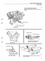
F. Engine, assembly
CYLINDER HEAD
Install cylinder heads one at a time i.e. perform operations
F1-7 separately for each cylinder head.
F1
Turn crankshaft to TDC for cyl. 1.
F2
Install guide sleeves in cylinder block
Secure the sleeves with e.g. a 3 mm drill. This prevents
the sleeves from being forced down when the cylinder
head is fitted.
F3
Install cylinder head gasket and cylinder head
First remove liner holder 5093 and then the protective
paper in the water passages.
Note! Different gaskets for right and left cylinder
heads.
F4
Set camshaft
Left side: groove in camshaft must point up and No. 1
rocker arms should have clearance.
Right side: groove in camshaft must point out and
down.
52
Group 21 Reconditioning
engine
Assembly
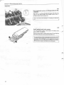
F5
Install rocker arm assembly
Use the correct bridge on the right and left sides. Bridges are the same but must face different directions.
- left side circlip must face forwards and
- right side circlip must face rearwards.
245083-1
246949-2
F6
Clean, lubricate and install cylinder head bolts
(Remove 3 mm drill beneath guide sleeves.)
Tighten bolts by hand.
Two different types of cylinder head bolts are in use, depending on the thread length in the cylinder block.
Late type = bolt thread length 27 mm (1.063 in) with washer
Early type = bolt thread length 30 mm (1.181 in) without
washer
Only late type bolts are available as spare parts.
B27A
B 27 E/F
B 28 A, E, F
Early type
Engine number
Late type
Engine number
11374
57276
11375
57277
All
6%=C^S>5
5
If late type bolts are used on early type cylinder heads,
washers must be used (the same washers as used for late
type bolts).
F7
J-
Tighten cylinder head bolts
Tighten to the correct torque in three stages.
1 = 10 Nm ( 7 ft.lbs.)
2 = 30 Nm (22 ft.lbs.)
3 = 60 Nm (44 ft.lbs.)
3<§XZ^§>1
2#C^#4
4#C^#2
7#C^§>8
8#C^§>7
H
F8
Install other cylinder head
Install according to C53-65.
53
Group 21 Reconditioning
engine
Assembly
F9
Angle-tighten cylinder head bolts
At the earliest, 10-15 minutes after F7.
1 = Slacken all bolts in order shown adjacent
2 = Tighten to a torque of 15-20 Nm (11-15 ft.lbs.) in
order shown
3 = Angle-tighten 113-117° in order shown adjacent.
Use protractor 5098. The rocker arm bridge can be
used as a line of sight.
IMPORTANT! Bolts must be retightened after engine has
cooled.
TIMING GEARS
F10
Install crankshaft gears and keys
Block holes in crankcase to prevent keys from falling
in.
Lubricate parts.
The mark on the inner gear must face out.
Note! On late types, gear and spacer are manufactured
in one unit.
F11
Install:
-
I
new strainers in cylinder block
chain tensioners
straight chain dampers
bent chain dampers. Apply locking fluid
(P/N 116 1053-2) to bolts.
F12
Set crankshaft and left-hand camshaft
The key in the crankshaft should point towards the lefthand camshaft.
The groove in the camshaft should point upwards and
there should be no clearance between the rocker arms
and valve stem tops for No. 1 cylinder.
s
54
Group 21 Reconditioning
engine
Assembly
F13
Install left-hand camshaft chain and sprocket
Place the chain on the camshaft sprocket, with the mark
on the sprocket between the two marks on the chain.
Place the chain on the inner crankshaft sprocket, with
the mark on the chain opposite the mark on the sprocket.
Stretch the chain on the pulling side (the side against
the straight chain damper).
°,mm
mm
Position the camshaft sprocket. Make sure that the
sprocket fits in the groove in the camshaft.
Install the centre bolt.
RRH
F14
%
•:;:t
Set crankshaft and right-hand camshaft
Install the crankshaft nut. Turn the crankshaft clockwise
so that the key points directly downwards.
+m
The groove in the camshaft should point outwards, see
fig., and there should be no clearance between the rocker arms and valve stem tops for No. 6 cylinder.
/
1
K
iT
F15
Install right-hand camshaft chain and sprocket
Place the chain on the camshaft sprocket, with the mark
on the sprocket between the two marks on the chain.
Place the chain on the camshaft sprocket, with the mark
on the chain opposite the mark on the sprocket.
Stretch the chain on the pulling (the side against the
straight chain damper.)
Install the camshaft sprocket. Make sure that the sprocket fits in the groove in the camshaft. If necessary rotate
the crankshaft slightly.
Install the centre bolt.
Fl
Tighten both camshaft centre bolts
Tighten to a torque of 70-90 Nm (52-66 ft.lbs.) Use a
screwdriver as a counterhold, placing it between two
cogs on the sprocket without holes.
55
Group 21 Reconditioning
engine
Assembly
F17
Turn locks 1/4 turn clockwise
F18
Set chain tension
Turn the crankshaft round twice.
Remove the crankshaft nut.
Note! The key in the crankshaft should point upwards to
prevent it from falling out of its groove.
When the crankshaft has been rotated the marks for the
chains and sprockets do not coincide. It is necessary to rotate the crankshaft a large number of turns to obtain the
correct position.
F19
Install:
- oil pump with sprocket
- chain and gear.
Apply locking fluid (P/N 116 1053-2) to the bolts.
•
F20
Remove protective paper. Install timing gear
case
* v
Use new gaskets.
Smear the four lower bolts with locking fluid P/N
116 1056-5.
Tightening torque 10-15 Nm (7-11 ft.lbs.).
Cut sides of gaskets flush with cylinder heads.
56
Group 21 Reconditioning
engine
Assembly
CRANKSHAFT FRONT OIL SEAL, PULLEY
F21
Install new seal in timing gear case
Grease the seal.
Use drift 5103.
F22
Install crankshaft pulley
Fit locking sector 5112 to the flywheel casing at the
lower bolt (RHD-vehicles = upper bolt.)
Make sure that key in crankshaft does not fall out.
Tighten nut to correct torque, see left.
36 mm socket.
IMPORTANT! There are two different types of nuts.
\
X
45 mm
/
160-180 Nm
240-280 Nm
(118-133 ft.lbs.)
(177-206 ft.lbs.)
TIMING SCALE
Check/adjust only if necessary, eg if plate is removed or
replaced.
F23
Remove rear plug in cylinder block
57
Group 21 Reconditioning
engine
Assembly
F24
Set crankshaft statically
36 mm socket.
Turn the crankshaft so that the markforT.D.C. cylinder 1
aligns with the 20° mark on the timing scale.
Note! There are two marks on the pulley, 1 = T.D.C.
cylinder 1 and 2 = T.D.C. cylinder 6.
•
•
F25
Set crankshaft at T.D.C. cylinder 1
Insert a 8 mm drill (0.315 in) in the blanking plug hole so
that it rests on the crankshaft counterweight.
Press lightly on the drill and turn the crankshaft slowly
in the normal direction of rotation until the drill fits into
the hole in the counterweight.
The engine is now set at exactly T.D.C. for cylinder 1.
F26
Check/adjust timing scale
The zero-mark on the scale must align exactly with the
mark on the pulley.
C
-
F27
Install blocking plug
Use a new seal.
Tightening torque 35-40 Nm (26-30 ft.lbs.
Before proceeding with valve clearance check:
Camshaft setting must be checked. See specifications on page 8.
53
Group 21 Reconditioning
engine
Assembly
VALVE ADJUSTMENT, VALVE COVERS
See footnote on page 58.
Different clearances for different engine types
Valve clear ince mm (in),
cold engine
intake...'
exhaust
B27 A 1976-1979
B28A 1980
1981-1982
B27E 1975-1978
1979-1980
Sweden and Australia
1979-1980 Other
markets
B28E 1981-1983
B27F 1976-1979
B27F 1980
B27F 1981-1982
Type 1
Type 2
0.10-0.15
(0.004-0.006 in)
0.25-0.30
(0.010-0.012 in)
0.20-0.25
(0.008-0.010 in)
0.30-0.35
(0.012-0.014 in)
X
X
X
X
X
X
X
X
X
X
F28
Turn crankshaft to firing position for No. 1 cylinder
The mark " 1 " on the pulley should align with the zeromark on the timing scale. Both rocker arms for No. 1
cylinder should have clearance.
F29
Check/adjust valve clearances
Check the following valves in the set position.
Intake: cylinders 1, 2 and 4
Exhaust: cylinders 1, 3 and 6
F30
Turn crankshaft one turn in normal direction to
overlap position for No. 1 cylinder
—*"
The mark " 1 " on the pulley should align with the zeromark on the scale. There should be no clearance between the rocker arms and valve stem tops for No. 1
cylinder.
CYL 1 TDC OVERLAP
F31
Check/adjust valve clearances
If Tf TT
Check the following valves in the set position.
Intake: cylinders 3, 5 and 6
Exhaust: cylinders 2, 4 and 5
59
Group 21 Reconditioning
engine
Assembly
F32
Turn crankshaft one turn to firing position for No.
1 cylinder
The mark " 1 " on the pulley should align with the zeromark on the timing scale. The rocker arms for No. 1
cylinder should have clearance.
This is now the correct setting for installing the distributor.
F33
Install gaskets and valve covers
Use new gaskets. Apply a few spots of sealing compound. (P/N 116 1026-8).
Place only four bolts in each valve cover. Do not tighten
since the covers are to be removed later on.
To ensure that the junction between the valve cover, cylinder block and timing gear case is fully leak-proof, a thin coat
of silicone (P/N 116 1048-2) can be applied to the joint.
Note! Do not use too much silicone otherwise it may enter
the lubrication system and block the oil channels.
60
Group
21 Reconditioning
engine
Index
Index
Camshaft
removal
endfloat
installation
Carrier plate (Auto)
removal
inspection
installation
Chain dampers, tensioners
removal
different types
inspection
installation
Clutch
removal
installation
Connecting rod bearings
removal
installation
Connecting rods
side clearance
removal
bolts, replacement
inspection
replacement
different types
installation
Crankshaft oil seal
rear, r e m o v a l
installation
front, r e m o v a l
installation
Crankshaft pulley
removal
installation
Crankshaft
removal
inspection
different types
instal/at/on
end clearance
Cylinder block
cleaning-checking
62
Operation
Page
El
E5
E25
46
47
51
B17
C34
D34
25
36
45
B5-6
C31
C32
F11
22
35
35
54
B18
D35
25
45
B15-16
D20-24
24
43
B14
B15-16
C10-11
C7
C20-29
C20
D20-24
24
24
28
23,
28,33
32
32
43
B17-18
D7-8
25
39
B2
F21
21
57
B1
F22
21
57
B19
C18-19
C20
D1-6
D4-5
25
31
32
38
38
C12
29
Operation
Cylinder liner
classes
diameter
removal
inspection
liner height
installation
Cylinder head gasket
installation
Cylinder head
removal
disassembly
cleaning-checking....
warp
assembly
bolts, different types .
installation
bolts, tightening
Flywheel
removal
inspection
ring gear replacement
installation
Gudgeon pins
checking
removal
installation
Lower crankcase
removal
installation
Main bearings
removal
installation
end float
nuts, t i g h t e n i n g
Oil pump
removal
cleaning-checking... .
installation
Oil strainer
removal
installation
P
Page
C1
C4
C5-6
C7
D10-13
D14-19
26
27
27
28
40
41
F3
52
B8-11
E1
E2-3
E4
E25
F6
F1-9
F7-9
23
46
46
46
51
53
52
53
B18
C34
C35-39
D34
25
36
36
45
C7
C23
C25-29
28
33
33
B12
D25-32
23
43
B19
D1-6
D4-5
D29-31
25
38
38
44
B7
C40
F19
22
37
56
B12
23
033
45
Group 21 Reconditioning
engine
Index
Operation
/ ^
Overflow (relief) valve
(in cylinder block)
checking, different types
replacement
Pilot bearing (manual)
removal
installation
Piston pins
see Gudgeon pins
Piston rings
removal
axial play
ring gap
installation
Pistons
removal
types, manufacturer
diameter
clearance
inspection
replacement
installation
Pressure plate
removal
installation
Ring gear
replacement
RocKer arms
removal
cleaning-inspection
installation
Sump
removal
installation
Thread inserts
general information
installation
non repairable threads
thread inserts
drill sizes
spark plug threads
installation
removal
Operation
Page
C14
C15-17
30
30
B18
D9
25
40
C7
C8
C9
C30
26
28
28
35
B15-16
C1-2
C3
C4
C7
C20-29
D20-24
24
26
26
27
28
32
43
B18
D35
25
45
C35-39
36
B8
E26
F5
23
51
53
B12
D33
23
45
A1
A2
A3
A4
A4
A5
A6-11
A12-14
14
14
15
16
16
16
17
19
Timing gear chains, sprockets
wear check
removal
inspection
installation
Timing gear cover
removal
installation
Timing scale
checking-adjusting
Valve covers
removal
installation
Valve guides
clearance
replacement
oil seals, removal
oil seals, installation
Valve seats
grinding
replacement
Valve springs
removal
inspection
installation
Page
B3
B4-7
C33
F10-19
21
22
36
54
B2
F20
21
56
F23-27
57
B2
F33
21
60
E6
E8-14
El
E25
47
47
46
51
E24
E15-22
50
49
E1
E7
E25
46
47
51
E1
E23
E25
F28-32
46
50
51
59
Valves
removal
grinding
installation
adjustment
Vibration damper
see Crankshaft pullley
63
r
VOLVO SUPPORTS VOLUNTARY
MECHANIC CERTIFICATION
BY THE N.I.A.S.E.
r
(U.S.A. Only)
Service literature
Your
most important
special tool