1
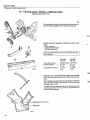
Service Manual
Section 2 (excl.
group 23)
N
Repairs r
and Maintenance
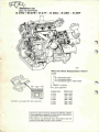
B 27, B 28
Engines
260 1975-1983
^777623*5-0
*3v
bwksicarsxoffi
$88(1 Wth Avenue South
A
B2m^2W
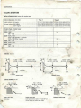
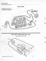
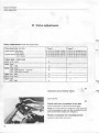
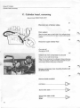
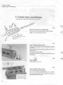
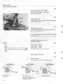
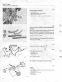
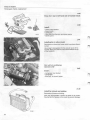
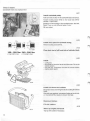
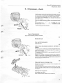
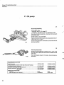
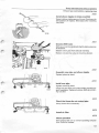
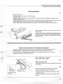
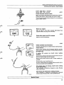
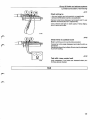
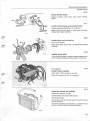
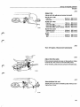
- B 27F - B 28A - B 28E - B 28F
What do these designations mean?
B 28E
A = carburetted engine
E = fuel injected engine
F = fuel injected engine "USA models'
^
28(27) = capacity
B = petrol (gasoline)
The B28 is in principle a B27 with a larger bore.
Engine type
Model year
B 27A
B 28A
1976-1979
1980-1982
B 27E
B 28E
1975-1980
1981-1983
B 27F
B 28F
1976-1979
1980-1982
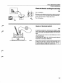
Volvos are sold in versions adapted for different markets.
These adaptations depend on many factors including legal, taxation and market requirements.
This manual may therefore show illustrations and text
which do not apply to cars in your country.
y
*« ft-7-C2
A-12-0/
C ; 7776225-0
ENG R
BZ/
VOR
^o^
C1402t
ORIGINAL
PARTS
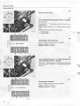
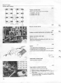
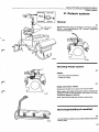
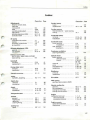
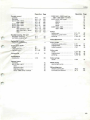
Contents
Page
Important information
3
Specifications
Special tools
11
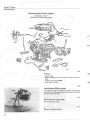
Group 2 0 General description
14
(Connection of vacuum hoses)
Group 2 1 Engine assembly
26
Group 22 Lubricating system
85
Group 25 Intake and exhaust systems
93
•
m
(Exhaust gas purification systems)
Group 26 Cooling system
142
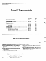
Group 27 Engine controls
154
Index page 167
•
Order number TP 30430/1
This manual togetherwith Section 2 (21) supersedes
service manual Section 2 Engine B27 with order
number TP 11409.
We reserve the right to make alterations.
r"-
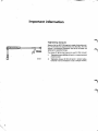
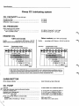
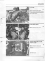
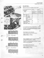
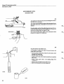
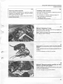
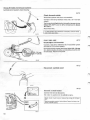
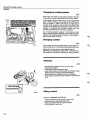
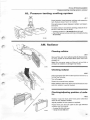
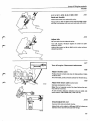
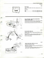
Important information
Tightening torques
Nearly all of the B 2 7 / 2 8 engine is made of aluminium alloy. The threads are tapped directly into the alloy. For this
reason it is extremely important that all of the bolts are
tightened to specified torque.
Two types of tightening torques are used in this manual:
135 020
I.
Tightening torque 4 0 Nm (4 kpm) = a torque wrench
must be used.
II.
Tightening torque 4 0 Nm (4 kpm) = correct value,
however it is not necessary to use a torque wrench.
S*
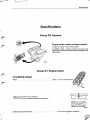
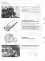
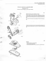
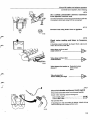
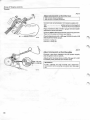
Specifications
Specifications
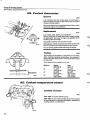
Group 20 General
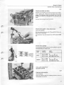
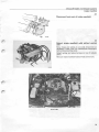
Engine serial number and part number
Located on a plate in front of the oil filter.
On B28E/F 1 9 8 1 - models: located on the rear of the
right-hand cylinder head, shows the last three digits of the
part number.
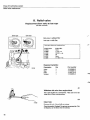
Group 21 Engine block
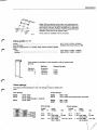
CYLINDER HEAD
Height
Max. warp is 0.05 mm over 100 mm.
NOTE! Do not level a warped cylinder head, replace it.
New = 111.07 mm (4.373 in)
i
I
129 880
Cylinder head gasket thickness
1.14-1.50 mm (0,045 - 0.059 in)
W
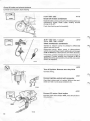
Specifications
VALVE SYSTEM
V a l v e c l e a r a n c e s (varies with engine type)
Valve clearance m m (in)
Type 1
Intake valves, cold engine
0.10-0.15
0.15-0.20
0.25-0.30
0.30-0.35
Exhaust valves, cold engine
warm engine
Type 2
(0.004-0.006)
(0.006-0,008)
(0.010-0.012)
(0.012-0.014)
0.20-0.25
0.25-0.30
0.30-0.35
0.35-0.40
(0.008-0.010)
(0.010-0.012)
(0.012-0.014)
(0.014-0.016)
Engine type - model year
B27A 1976-1 979
X
B28A 1980
1981-1982
X
"'
X
B27E 1975-1978
1979-1980 Sweden + Australia
1979-1980 Other markets
X
X
B28E 1981-1983
X
B27F 1976-1 979
X
B28F1980
1981-1982
X
^
X
X
V a l v e s mm (ir
44,5°
29,5
7,965-7,980
(0,3135-0,3141)
1.7322)
7,975-7,990
(0,3139-0,3145)
sv
7,945-7,960
(0,3127-0,3133)
J)- 37 (1,4566)
7,965-7,980
(0,3135 - 0 . 3 1 4 ^
1
k9
T
Tapered
26,5
(1,0433
32 (1,2598)
Exhaust valves
Intake valves
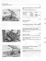
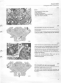
V a l v e seats mm (in)
1,7 -2,1 mm
(0,0669-0,0826)
Intake valve seat
Early types
1,3 - 1,7 mm
2,0 - 2,4 mm
(0,0511 - 0 . 0 6 6 9 )
(0.0787 - 0 , 0 9 4 4 )
Intake valve seat
Late types (venturi seat): 1 5° and 60° are
correct angles to reduce seat width.
Exhaust valve seat
<3
Specifications
Note! When replacing valve seats: the interference between the valve seat and its bore in the cylinder head must
be 0.070-0.134 mm, (0.0027-0.0052 in), i.e. the valve
seat diameter must be 0.070-0.134 mm greater than the
diameter of the bore in the cylinder head.
Valve seats are available in three oversizes.
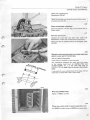
Valve guides mm (in)
Length
Inner diameter
,.
Press-in measurement to cylinder head contact surface against
block:
intake
exhaust
50.1-51.3 (1.2725-1.3030)
8.000-8.022 (0.3149-0.3158)
39.5-40.5 (1.5551-1.5944)
36.9-37.9 (1.4527-1.4921)
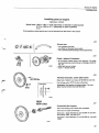
Valve guides are available in three oversizes, and are marked with
grooves.
Standard
Oversize 1
2
3
Marking
Reamer for seat
No groove
1 groove
2 grooves
3 grooves
5166
5167
5168
\_7
129 865
Valve springs
Two types of valve springs are in use. The springs are colour coded as follows:
Grey springs:
Green springs:
B27A
B27E
B28A
B27E
B27F
1976-1979
1975-1978
1979-1980 Sweden + Australia
1976-1979
B28E
B28F
- 1980-1982
1979-1980 (excluding Sweden, Australia)
1981-1983
1980-1982
Grey springs:
Length
mm
in
47.2
40.0
32.2
Green springs:
Load
N(kp)
lbs.
Length
mm
in
186 0
0
47.1
1.57 233-268
52-60
40.0
(23.3-26.8)
1.27 521-585
116-131 30.0
(52.1-58.5)
Load
N (kp)
1.85 0
1.57 230-266
(23.0-26.6
1.18 613-689
(61.3-68.9)
lbs.
0
51-59
137-154
/
/
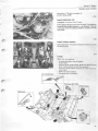
Specifications
Rocker arm mechanism
The rocker arm contact surface against the camshaft is surface-hardened and must not be ground.
Diameter, rocker arm shaft
Hole diameter, rocker arm
Clearance, shaft-rocker arm
19.959-19.980 mm 0.7857-0.7866 in
19.992-20.013 mm 0.7870-0.7879 in
0.012-0.054 mm 0.0005-0.0021 in
TIMING GEARS
Camshaft
Three types of camshafts with different lift heights are in use. The
part number is marked on the front end.
Camshaft
Type 1
Type 2
Type 3
Marking (part number), left
79 10245 522
(-143or-144)
74 01 269 138
7401 269615
*;•
\
right
fylax, Iift4jeight, left
mm
;w|
right
mm
Chel^pkcamshaft setting (cold engine):
Adjust valve clearance on 1 st and 6th intake valves to 0.7
mm (0,027 in), the intake valves should then open at,
1st
BTDC
6th
BTDC
79 1 0 2 4 5 4 1 2
5.144
(0.202 in)
74 01 269 139
6.004
(0.236 in)
7 4 0 1 269 616
5.96
(0.234 in)
5.059
(0.199 in)
9°±3°
7°±3°
6.004
(0.236 in)
9°±3°
90+30
5.96
(0.234 in)
30+30
30+30
"*V
Engine type
B27A1976-1979
B28A 1980
1981-1982 .
B27E 1975-1978
1979-1980 Sweden + Australia
1979-1980 Other markets
B28E 1981-1982 .
B27F 1976-1979
B28F1980
1981-1982
Journal diameter, counting from front (all types): mm (in)
1st
2nd
3rd
4th
Radial play
End float, new
max
40.440-40.465 (1.5921-1.5931)
41.040-41.065 (1.6157-1.6167)
41.640-41.665 (1.6393-1.6403)
42.240-42.265 (1.6629-1.6639)
0.035-0.085 (0.0013-0.0033)
0.070-0.144 (0.0027-0.0056)
0.5(0.0196)
•?£:
'«•
.('•
Specifications
CRANK MECHANISM
Flywheel
0 . 0 5 m m ( 0 . 0 0 1 9 in)
0 . 1 5 m m ( 0 . 0 0 5 9 in)
Run-out, max
Radial throw, max. (measured at 0 2 8 2 . 4 m m = 1 1.1 1 8 in)
•...
TIGHTENING TORQUES
The tightening torques shown below apply to oiled nuts and bolts.
Degreased (washed) parts must be oiled prior to assembly,
:
Cylinder head (see below)
Big end bearings
Crankshaft front end, 1 9 7 5 - 1 9 7 7
1978-
Nm
kpm
45-50
16CM 8 0
240-280
4.5-5.0
16-18
24-28
~ .>' ft: lbs
33-37
•ifi£-133
177-207
\
40 mm = 1.575 in
o
I 40)mm
45 mm = 1.771 in
1975-1977
1978-
Camshaft sprocket
Flywheel (always use new bolts)
Spark plugs (do not oil)
Valve cover
Nm
Kpm
ft. lbs
70-90
45-50
12+2
15
7-9
4 5-5 0
1 2+0 2
1.5
52-66
33-37
9±1.5
11
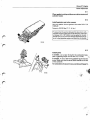
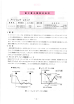
Tighten all bolts in stages according to below:
1
2
3
4
5
6
7
8
9
10
118 650
Tightening order for cylinder head bolts
=
=
=
=
=
=
=
=
=
=
10 Nm (1 kpm = 7 ft. lbs)
30 Nm (3 kpm = 22 ft. lbs)
60 Nm (6 kpm = 44 ft. lbs)
Wait 10-15 minutes
-^
Slacken bolts
15-20 Nm (1.5-2.0 kpm = 11-15 ft. lbs)
Angle-tighten to 113-11 7°
Warm-up engine to operating temperature
Cool block 30 minutes
Slacken and then retighten bolts one at a time in
specified tightening order.
Retighten according to stages 6 and 7.
Specifications
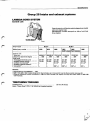
Group 22 Lubricating system
OIL CAPACITY
litres (US qts)
Excluding oil filter
Including oil filter
Difference, max-min approx.
6.0 (6.3)
6.5 (6.9)
1.0(1.0)
OIL PRESSURE
Warm engine and new oil filter
at 15 r/s (900 r/min) min
50 r/s (3 000 r/min)
0.1 MPa (1.0 kp/cm 2 = 14.2 psi)
0.4 MPa (4.0 kp/cm 2 = 57 psi)
ENGINE OIL
USA and Canada
O t h e r m a r k e t s (excl. USA and Canada)
Quality
according to API Service - SF/CC
Note! Under no circumstances may SE/CD oils be used.
Quality .. according to API Service - SE/CC or SF/CC
Viscosity:
Temperature range
(stable ambient temperatures)
Viscosity:
Temperature range
(stable ambient temperatures)
10
20
30
40 °C
^2^PTl™^2^pq8
86
104 *F
-30 -20 -10
i
i
I
i
SAE OW/SO , 5W/30
J^A^l
1
1_
!plliii#
Mm>
<r
SAE 15W/S0
^
SAE 20W/50
£
J>
SAE 3 0
c
SAE 40
SAE 1 5 W / 5 0 or 2 0 W / 5 0 oils are recommended for use in extreme driving conditions which involve high oil consumption and high oil temperatures e.g. mountain driving with frequent decellerations or fast motorway driving. Noter however the lower temperature limit.
CARBURETTOR
Oil for damper cylinder
SAE 10W-40 (or SAE 10W-50)
OIL PUMP
••*$? End float
iffi Radial play between cog tip and pump housing
' ' wall (excl. bearing play)
Backlash (excl. bearing play)
Bearing play, drive shaft
idler shaft
..Relief valve spring, length at various loads:
unloaded
loaded to 88.3 N (8.83 kp = 20 lbs)
\
8
\
0.025-0.084 mm 0.0009-0.0033 in
0.110-0.185 mm 0.0043-0.0072 in
0.17-0.27 mm 0.0066-0.0106 in
0.015-0.053 mm 0.0006-0.0021 in
0.015-0.051 mm 0.0059-0.0020 in
89.5 mm 3.52 in
56.5-60.5 mm 2.22-2.33 in
Specifications
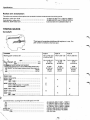
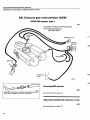
Group 25 Intake and exhaust systems
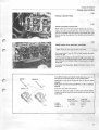
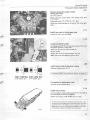
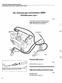
LAMBDA-SOND SYSTEM
Control unit
Type of control unit fitted to vehicle depends on model
year and engine type.
identification number stamped on side of unit (last
three digits).
0 280 800^7
13S 202
#*N
B27F
Engine type
Model year, market
Control unit
Volvo no
Bosch no (last three digits)
Duty cycle
disengaged lambda-sond .
earthed thermal switch
earthed microlswitch 21
earthed pressure differential switch 31
1978
1979
B28F
1980
1981
1981
Calif+Japan Fed+Canada
464443-1 1| 464958-8 1274143-5 1274143-5
. . . 005
. . . 023
. . . 003
. . . 023
42-48°
73-80°
42-48°
73-80°
1982
1274219-3
. . . 031
1274368-9
. . . 050
42-48°
51-57°
51-57°
42-48°
51-57°
51-57°
42-48°
51-57°
51-57°
42-48°
51-57°
51-57°
(820->)
(82°-»)
(82°->)
82°->
Remarks:
• Superseded by P/N 464958-8 (. . . 005)
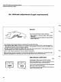
2) B28 F USA 1980-1982 models designed for high altitude use: microswitch must be disconnected, see page 64.
3
> Pressure differential switch introduced in 1982 on USA+Canada (not Japan) but may have been fitted to 1980-1981
USA+Canada.
TIGHTENING TORQUES
Lambda-sond
Apply "Never Seez" (P/N 1 161 035-9) to threaded section.
55 Nm (40 ft.lbs)
Specifications
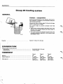
Group 26 Cooling system
GENERAL
Coolant — composition
Since we use aluminium in our engines, active corrosion protection is necessary in the coolant to help prevent corrosion damage.
50%
50%
Use genuine Volvo coolant, type C, diluted with clean
water in proportions of 50/50.
The mixture helps to prevent corrosion and frost
damage.
• Never fill the cooling system with water alone. Use
genuine Volvo coolant diluted with clean water in
proportions of 50/50.
• The coolant should be changed regularly since the
corrosion-protective additives in the coolant loose
their effect in time.
Approx 11 litres (11.5 US qts)
Capacity
EXPANSION TANK
Pressure valve in cap opens at:
overpressure
underpressure
65-85 kPA (9.2-12.0 psi)
7 kPa (1.0 psi)
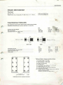
THERMOSTAT
Marking
Starts to open at
Fully open at
10
"ton
Type 1
Type 2
Type 3
82
81-83°C
(178-181°F)
90-94°C
(194-201°F)
87
86-88°C
(187-190°F)
95-99°C
(203-210°F)
92
91-93°C
(196-199°F)
100-104°C
(212-219°F)
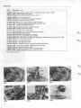
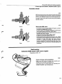
Special tools
Special tools
999
Description - use
1426-9 Drift: installing pilot bearing
1801-3 Standard handle: used with 5101 and 5953
2484-7 Centering drift: clutch, M 4 5 / 4 6 gearboxes (early types)
2520-8
2810-3
2903-6
4090-0
General stand: used with fixture 5099
Beam: for hoisting engine. Used with 2 X cradle 51 00
Oil filter wrench
Extractor: for removing pilot bearing
Continued on page 12.
1426
5099
A
^J&
b/
K J ^ **mJj
2520-—1 It
V
mm
116 M3
1801
2484
2520
2810
2903
4090
11
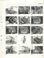
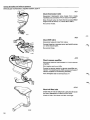
Special tools
999
Description - use
5006-5 Lifting tool: replacing engine mounts. Used with 2 x 5 1 1 5 and 2 x 5033
5029-7 Drift: Installing intake valve seats
5033-9 Support: two, used with 5006 and 2 x 5 1 1 5
5093-3 Holder: four, for cylinder liners
5098-2 Protractor: for angle-tightening cylinder head bolts
5099-0 Fixture: for engines. Used with 2520
5100-6 Hoist beam: two, hoisting engines, Used with 2810
5101-4 Drift: installing pilot bearing (early types). Used with 1801
5103-0 Drift: installing crankshaft front seal
5105-5 Support bracket: retaining camshaft sprocket
5108-9 Drift: installing intake valve guides
5109-7 Drift: installing exhaust valve guides
5111-3
5112-1
5113-9
5115-4
5165-9
5166-7
Centering drift: clutch, M 4 5 / 4 6 gearboxes, late types
Gear sector: blocking flywheel
Centering drift: clutch, M 5 0 / 5 1 gearboxes
Hook: two. Used with 5006 and 2 x 5033
Reamer kit: valve guides, contains 5164 (early types), 5224 (late types), 51 66, 5167, 5168
Reamer: for valve guide seat OS 1
5167-5 Reamer: valve guide seat OS 2
5168-3 Reamer: valve guide seat OS 3
5213-7 Reamer: camshaft sprocket, removing/installing cylinder head
5218-6
5220-2
5224-4
5953-8
Drift: removing valve guides. Installing seal in valve guide
Drift: installing exhaust valve seats
Reamer: reaming of guides. 5164 can also be used.
Drift: installing crankshaft rear seal. Used with 1801
Continued on page 14.
5006
5029
5033
Special tools
5112
5113
5115
5213
5165 (5166, 5167, 5168)
5213
5218
5220
5224
5953
13
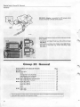
Special tools, Group 20
General
Contents
999 5151-9 Adapter: connected to CO gauge when
trouble shooting Lambda-sond system.
9724
9921
Additional equipment required when testing Lambdasond system:
- tachometer and dwell meter e.g. Volvo Mono-Tester
999 9921-1
- ohmmeter e.g. Volvo ohm-diode meter 999 9724-0
- test lamp or voltmeter e.g. Volvo Volt-Amp meter
999 6450-4.
6450
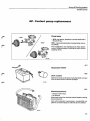
Group 2 0 General
Connection of vacuum hoses
Page
B 27/28 A
B 27 E 1975-1977
1978
1979 Sweden and Australia
1980 Sweden and Australia
1979-1980 Other markets
B 28 E 1981-1982 Sweden and Australia
1981-1983 Other markets
B 27 F 1976-1977 type 1
1976-1977 type 2
1976-1977 type 3
1978
1979
B 28 F 1980-1981
1981-1982
15
15
16
17
18
16
18
16
19
20
21
22
23
24
25
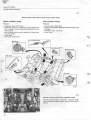
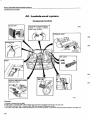
The illustrations in this section show where the vacuum hoses are connected. The exact
routing of the hoses is not however shown.
14
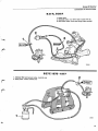
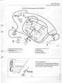
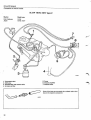
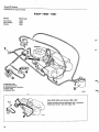
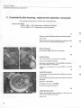
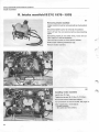
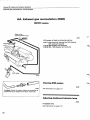
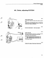
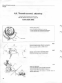
Group 20 General
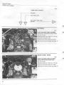
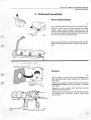
Connection of vacuum hoses
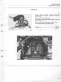
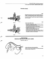
B27A, B28A
1. Delay valve
2. Solenoid valve: only 1979-1982 models with AC
3. Non-return valve: white side facing intake manifold
^5f^^k
J ^
135021
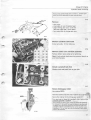
B27E 1975-1977
1 . Charcoal filter and vacuum valve. Australia only
2. Delay valve. Certain markets only
f^
135022
15
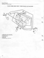
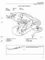
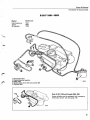
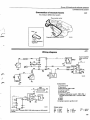
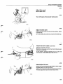
Group 20 General
Connect/on of vacuum hoses
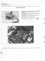
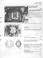
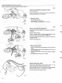
B27E 1978
1. Charcoal filter. Australia only
2. Delay valve. Certain models only
3. Vacuum valve. Australia only
>
135023
B27E 1979-1980, B28E 1981-1983
Excluding Sweden and Australia
1. Solenoid valve. Only cars with AC
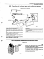
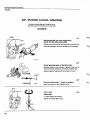
Group 20 General
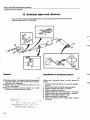
Connection of vacuum hoses
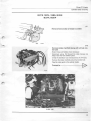
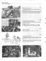
B 27E 1979 Sweden and Australia
1.
2.
3.
4.
Delay valve. Certain models only
Solenoid valve. Only cars with AC
Thermostat valve
Vacuum valve. Australia only
5. Charcoal filter. Australia only
6. *EGR valve
7. Air inlet for filter
8. Vacuum amplifier
'Exhaust gas recirculation
Impulse relay
Cars for Australia only
If, as a service fix, the vehicle has been equipped with
an impulse relay for the cold start injector, then there
should be a delay valve (yellow), filted on the hose between the vacuum valve and distributor.
17
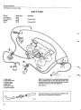
Group 20 Genera/
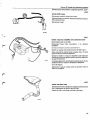
Connect/on of vacuum hoses
B 2 7 E 1980, B 2 8 E 1 9 8 1 - 1 9 8 2 Sweden and Australia
1.
2.
3.
4.
5.
6.
Delay valve. Certain models only
Solenoid valve. Only cars with AC
Thermostat valve
Delay valve
EGR valve
Charcoal filter. Australia only
18
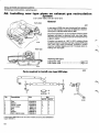
Group 20 Genera/
Connection of vacuum hoses
B 27F 1976-1977 type 1
Market
Model year
Remarks
USA Federal
Canada
1976
1976-1977
Exhaust gas recirculation (EGR) automatics only
Exhaust gas recirculation (EGR) automatics only
"^iBV
1.
2.
3.
4.
Thermostat valve
EGR valve
Charcoal filter and vacuum valve
Pump
.135027
Z^
Some of the hoses are connected via an adapter and a
short hose to the respective component
135028
19
Group 20 General
Connection of vacuum hoses
B27F 1976-1977 type 2
Market
Model year
USA California
Japan
1976
1976-1977
S
fS^-
/&F
135029
1.
2.
3.
4.
5. Pump
6. Vacuum amplifier
7. Solenoid valve
Thermostat valve
EGR valve
Charcoal filter and vacuum valve
Air inlet, air filter
Some of the hoses are connected via an adapter and a short
hose to the respective component.
135028
20
'
Group 20 General
Connection of vacuum hoses
B 2 7 F 1976-1977 type 3
Market
USA Federal
USA California
Model year
Remarks
1977
1977
Without pump
W^s^f
California
/"^
1.
2.
3.
4.
Solenoid valve. California only
Delay valve
Thermostat valve
EGR valve
5.
6.
7.
8.
Charcoal filter and vacuum valve
Pump
Vacuum amplifier
Air inlet, air filter
Some of the hoses are connected via an adapter and a
short hose to the respective component.
21
Group 20 General
Connection of vacuum hoses
B27F 1978
Market
Model year
Remarks
USA Federal
USA California
Canada
Japan
1978
1978
1978
1978
Without EGR
Without EGR
jmmx^
135031
1. Delay valve
2. Thermostat valve
3. Vacuum valve
4. Charcoal filter
5. EGR valve
6. Air inlet, air filter
7. Vacuum amplifier
Note! If, as a service fix, the vehicle has been equipped
with an impulse relay for the cold start injector, then
there should be a delay valve (yellow) fitted on the hose
between the vacuum valve and distributor.
See page 23.
Some of the hoses are connected via an adapter and a
short hose to the respective component.
22
Group 20 General
Connection of vacuum hoses
B27F 1979
All markets
^^^^^
1. Solenoid valve
2. Vacuum valve
3. Charcoal filter
/*
S
Impulse relay
Note! If, as a service fix, the vehicle has been equipped
with an impulse relay forthe cold start injector, then there
should be a delay valve (yellow) fitted on the hose between the vacuum valve and distributor.
23
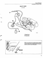
Group 20 General
Connection of vacuum hoses
B28F 1980-1981
Market
Model year
All markets
USA Federal
Canada
1980
1981
1981
1. Solenoid valve
2. Thermostat valve
3. Control pressure regulator
4. Delay valve
5. Charcoal filter
135033
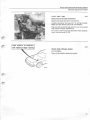
Note B28F USA and Canada 1980-1981
Some vehicles may be equipped with a pressure
differential switch. See also page 136.
136 321
24
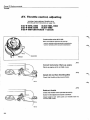
Group 20 Genera/
Connect/on of vacuum hoses
B 28 F1981-1982
Market
Model year
USA California
Japan
All markets
1981
1981
1982
1. Thermostat valve
2. Control pressure regulator
3. Delay valve
4. Vacuum valve. Only USA and Canada 1982
5. Charcoal filter
138084
Note: B 28 F USA and Canada 1980-1981
Some vehicles may be equipped with a pressure
differential switch. See also page 136.
25
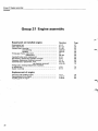
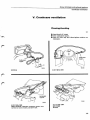
Group 21 Engine assembly
Contents
Group 21 Engine assembly
Repairwork on installed engine
Operation
Page
Compression test
Valve adjustment
Cylinder head, removing
reconditioning
installing
Timing gear chains, wear check
replacement
Camshaft/rocker arms, replacement
Pilot bearing, replacement (gearbox removed)
Ring gear, replacement (flywheel removed)
Crankshaft seal, replacement, front
rear (gearbox removed)
Timing scale, checking/adjustment of position,
or replacement
Engine mountings
A1-2
B1-13
C1-25
C26-52
C53-91
D1
D2-48
E1-5
F1-5
G1-5
H1-18
H19-25
27
28
32
40
46
55
56
66
68
69
70
73
J1-9
K1-2
75
77
L1-4
L14-17
L18-24
78
80
83
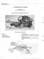
Replacement of engine
Removing and installing engine
Removing parts from engine
Installing parts on engine —
26
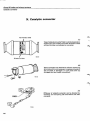
Group 2 7 Engine
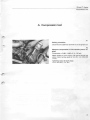
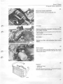
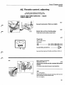
Compression test
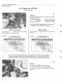
A. Compression test
A1
Safety precaution
Disconnect the cable from terminal 1 5 on the ignition coil.
A2
Measure compression at full throttle (warm engine)
Compression = 0.8-1.1 MPa (114-156 psi)
Note! Applies to warm engine, fully opened throttle and
starter motor turning speed of 4.2-5.0 r/s (250-300
r/min.)
Tightening torque for spark plugs:
1 2 ± 2 Nm ( 9 ± 1 . 5 f t . lbs.)
27
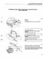
Group 21 Engine
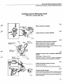
Valve adjustment
B. Valve adjustment
V a l v e c l e a r a n c e s (varies with engine type)
Valve clearance m m (in)
Type 1
Intake valves, cold engine
warm engine
Exhaust valves, cold engine
warm engine
0.10-0.15 (0.004-0.006)
0.15-0.20 (0.006-0,008)
0.25-0.30(0.010-0.012)
0.30-0.35 (0.012-0.014)
Type 2
0.20-0.25
0.25-0.30
0.30-0.35
0.35-0.40
(0.008-0.010)
(0.010-0.012)
(0.012-0.014)
(0.014-0.016)
Engine type - model year
B27A 1976-1979
X
B28A 1980
1981-1982
X
X
B27E 1975-1978
1 979-1 980 Sweden + Australia
1979-1980 Other markets
X
X
B28E 1981-1983
X
B27F 1976-1979
X
B28F1980
1981-1982
X
X
X
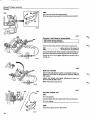
B1
Disconnect one of battery cables
Cars with AC
B2
Detach and move compressor to one side
Secure compressor to right bonnet/hood hinge.
Note! Do not disconnect the refrigerant hoses otherwise
it will be necessary to drain and then ecacuate the complete system before adding new refrigerant.
Remove compressor rear mounting bracket
Located on right hand valve cover.
116 108
28
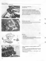
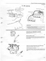
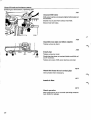
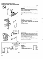
Group 21 Engine
Valve adjustment
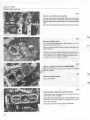
B 27/28A
B3
Obtain access to valve covers
Detach carburettor and baseplate, and air filter. Place assembly on intake manifold. Cover
hole in intake manifold.
134 960
B 27E 1975-1978
B4
Obtain access to valve covers
B 2 7 E 1979-1980, B 28E,
B27F, B28F
B5
Obtain access to valve covers
Remove vacuum pump and air pump where
necessary.
B28F 1981 model
29
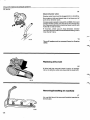
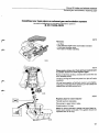
Group 21 Engine
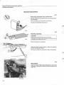
Valve adjustment
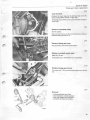
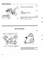
B6
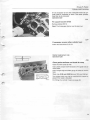
Remove valve covers
B7
Turn crankshaft to firing position for IMo. 1 cylinder
36 mm socket.
The pulley mark " 1" should align with the O-mark on the
timing scale.
Both the rocker arms for No. 1 cylinder must have clearance.
Mote! There are two marks on the pulley:
1 = TDC cylinder 1
2 = TDC cylinder 6
ST.
B8
I?
r
CYL 1 TDC FIRING
3
2
Check/adjust valve clearance
Check the following valves in the set position.
Intake: cylinders 1,2 and 4
Exhaust: cylinders 1,3 and 6
1
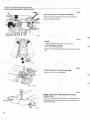
B9
Turn crankshaft one turn in normal direction to
overlap position for No. 1 cylinder
The mark " 1" should align with the O-mark on the timing
scale. The rocker arms for No. 1 cylinder should not have
clearance.
B10
Check/adjust clearance
Check the following valves in the set position:
Intake: cylinders 3, 5 and 6
Exhaust: cylinders 2, 4 and 5
30
Group 21 Engine
Valve adjustment
B11
Clean gasket mating surfaces on valve covers and
cylinder heads
B12
Install gaskets and valve covers
Use new gaskets. Secure gaskets with sealer (P/N 116
1026-8).
Torque to 10-15 Nm (7-11 ft. lbs.)
To ensure that the junction between the valve cover, cylinder block and timing gear case is fully leak-proof, a thin coat
of silicone (P/N 116 1048-2) can be applied to the joint.
Caution I Do not use too much silicone otherwise it may enter in to the lubrication system and block the oil channels.
135 034
B13
Install parts
B 27/28A: use a new 0-ring for the carburettor baseplate. Tightening torque 10-15 Nm (7-11 ft. lbs)
B 27/28E, F: use a new O-ring (gasket) for the vacuum,
pump. Make sure that the pump shaft meshes on the top
of the camshaft.
For connection of vacuum hoses, see Group 20 page 14.
135 035
%\
31
Group 21 Engine
Cylinder head, removing
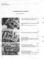
C. Cylinder head, removing
Special tools: 5093, 5105, 5213
C1
Disconnect one of battery cables
C2
Drain coolant
Open the drain taps on each side of the cylinder block.
Hoses can be connected to the taps to assist collecting the
coolant.
C3
Disconnect upper radiator hose
132 538
Cars with AC
Operations C4-5
C4
Detach and move compressor to one side
Secure it to the right bonnet hinge.
Note! Do not disconnect the refrigerant hoses otherwise
it will be necessary to drain and then evacuate the complete system before adding new refrigerant.
C5
Remove compressor rear mounting bracket and
lift off drive belt
134 963
C6
Remove intake manifold
B 27/28 A
B27E 1975-1978
B 27E 1979-1980, B 28E,
B27F,
B 28F
32
>
Group 21 Engine
Cylinder head, removing
B 27/28 A
C7
Remove intake manrfold including carburettor
and air filter
Disconnect first the hot spot pipe.
Disconnect wiring, hoses and cables. Identify connections
where necessary.
Place the cable harness between the cylinder heads.
Plug the intake ports in the cylinder heads.
Proceed to
c?£>
33
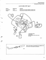
Group 27 Engine
Cylinder head, removing
B27E 1975-1978
C8
Remove intake manifold together with air-fuel
control unit
Disconnect wiring, hoses and cables. Identify connections
where necessary.
Pull forward the cable harness and hang it over the front
radiator panel.
Plug the intake ports in the cylinder heads.
Proceed to —
134 967
34
E>
Group 27 Engine
Cylinder head, removing
B27E 1979-1980, B28E
B27F, B28F
C9
Remove front section of intake manifold
<
«3j$
135 036
CIO
Remove intake manifold along with air-fuel control unit
Detach hoses and cables where necessary.
Disconnect wiring. Pull forward the cable harness and
hang it over the front radiator panel.
Unclip the distributor cap and disconnect the HT-leads.
Remove the intake manifold and air-fuel control unit.
Plug the intake ports in the cylinder heads.
Proceed to
cn>
B 28F 1981
35
Group 21 Engine
Cylinder head, removing
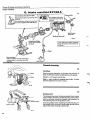
Cll
Remove parts which restrict access to the cylinder heads.
Right cylinder head
Left cylinder head
Remove:
Remove:
- distributor cap and HT-leads
- distributor. First turn crankshaft to firing position for
No. 1 cylinder, rotor arm points towards mark in distributor body
- (only vehicles with air pump): separate air blower pipe
at rear of engine
- water hoses
- EGR valve, where fitted.
- vacuum pump, where fitted
- air pump, where fitted. Separate air induction pipe at rear
of engine
- (A-engines only): fuel pump
- water hoses.
Distributor
*
[fiZ/j
..
VvvM
Hi 3f) wM
d
/PiiiP^i w
EGR valve
135 037
C12
Detach exhaust pipes from cylinder heads
Push the exhaust system rearwards. It may be necessary to unhook the rubber support rings next to the centre
silencer.
36
Group 21 Engine
Cylinder head, removing
Remove the cylinder heads one at a time i.e. perform operations C1 3-23 separately for each cylinder head.
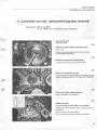
C13
Remove:
- valve cover
- cover plate at rear of cylinder head
- plug in timing gear case, use 8 mm
Allen key (right side = cover plate)
- four upper bolts for timing gear case.
C14
Slacken camshaft centre bolt
A few turns only. 10 mm Allen key.
C15
Remove rocker arm and shaft assembly
Remove bolts in same order as for tightening.
Note! If both cylinder heads are to be removed, identify to
avoid interchanging.
C16
Detach camshaft lock fork
Slacken bolt and push fork to one side.
C17
Secure timing gear chain
Use retainer 5213.
Hook the retainer under the chain. Tighten the nut by hand.
Secure the retainer to the timing gear case.
Turn the knob to keep the camshaft chain taut and the
camshaft sprocket in position.
521 3 keeps the timing gear chain taut when the camshaft
is removed. If the tool is not used the slack in the chain will
be taken up by the chain tensioner and this will make it impossible to lift the camshaft into the correct position when
installing it. To put this right the timing gear case would
have to be removed.
132 546
37
Group 21 Engine
Cylinder head, removing
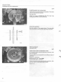
C18
Detach camshaft from sprocket
Unscrew the camshaft centre bolt, Allen key 10 mm. The
left hand bolt can be unscrewed but not removed. Make
surethatthe bolt does not fall down into the timing gear
case.
Move the camshaft backwards to free it from the sprocket.
C19
Remove cylinder head
The cylinder head must not be lifted directly up. Use a
hammer shaft to lever it off.
Place the cylinder head on blocks to prevent damage to the
gasket surfaces.
Make sure that the liners do not separate from their seals in the
lower liner seat. If this happens, coolant can flow down into
the crankcase, and it will be necessary to remove, disassemble and clean the engine thoroughly.
C20
Remove gasket and fit liner holders 5 0 9 3
The liner holders must always be used when the cylinder
head is removed.
C21
Remove guide sleeves
Use a pair of pliers.
C22
Clean gasket surfaces on cylinder block
Place paper under the cylinder liners to prevent dirt from
entering the water passages.
None of the liners should be loose when cleaning the cylinder block. Move the holders to the edge one at a time.
Use a plastic scraper.
Blow-clean the holes for the cylinder head bolts.
38
Group 21 Engine
Cylinder head, removing
If it is necessary to turn the crankshaft when the cylinder head is removed, or even if the other cylinder
head has to be removed:
Operation C23
C23
Fit support bracket 5 1 0 5
Remove retainer 5213.
Note! The timing gear chains must be kept taut.
C24
If necessary remove other cylinder head
Follow the instructions C1 3-23.
Gasket replacement
Operation C25
only
C25
Clean gasket surfaces and check for warp
Clean the valve cover as well.
Use a plastic scraper and if necessary a fine grade wet abrasive paper.
Use a straight edge and feeler gauge to check for unevenness.
Warp max. 0.05 mm (0.002 in) over 100 mm (3.94 in).
The cylinder head must not be machined but instead replaced if the warp is too great.
116 177
For fitting the cylinder head, see page 46.
39
Group 21 Engine
Cylinder head, reconditioning
C. Cylinder head, reconditioning
Special tools: 5108, 5109, 5029, 5165, 5218,
5220
C26
Remove all parts from cylinder head
Take care not to score/damage the mating surfaces.
Note! Do not interchange valve parts.
C27
Clean cylinder head and parts
Remove carbon deposits from the combustion chambers
and valves.
Clean valve seats with a grinder (to be able to see cracks,
damage, etc.).
Clean gasket mating surfaces.
Use a plastic scraper and if necessary a fine grade wet abrasive paper.
•
C28
Check all parts
Visible damage, wear, etc.
C29
Check cylinder head for warp
Use a straight edge and feeler gauge.
Warp = max. 0.05 mm (0.002 in) per 100 mm (3.94 in).
The cylinder head must not be machined but instead replaced if the warp is too great.
40
Group 21 Engine
Cylinder head, reconditioning
C30
Check camshaft end float
Position the camshaft and make sure that it turns easily.
Fit the locking fork. Measure the end float with a feeler
gauge. The clearance must not exceed max. 0.5 mm
(0.020 in). Replace the locking fork if the end float is too
large.
Remove the locking fork and camshaft.
C31
Check valve guide - valve clearances
Use a dial indicator.
Use new valves and press up 5-10 mm (0.2-0.4 in) with
finger when measuring.
The clearance must not exceed max. 0.1 5 mm (0.0059
in).
C32
Check valve springs
The springs are colour coded, and two different types are
used depending on engine type.
Colour
code
Length,
mm (in)
Load
N (lbs.)
GREY
47.2(1.86)
40.0 (1.57)
32.2(1.27)
0
0
233-268 (52-60)
521-585(116-131)
GREEN
47.1 (1.85)
40.0(1.57)
30.0(1.18)
0
0)
230-266(51-59)
613-689(137-154)
•
Valve guide replacement
Operation C33-39
C33
Press out valve guides
Use drift 5218.
Place the cylinder head on a sloping surface so that the
valve guides are vertical.
41
Group 21 Engine
Cylinder head, reconditioning
C34
Select a new valve guide, one size larger than old
one
The valve guides are marked with grooves.
51661
5167^5165
5168J
Valve guide
Mark
Reamer
Standard +
Oversize 1
2
3
no groove
1 groove
2 grooves
3 grooves
5166^
5167
5168
5165
C35
Ream seat for guide
See above table.
C36
Heat cylinder head to approx. + 1 5 0 ° C . ( + 3 0 0 ° F )
C37
Cool valve guide to approx. - 7 0 ° C (-95°F)
Use liquid carbon dioxide or equivalent to cool the valve
guides.
Wear protective gloves.
C38
Press in new guide
Note! This must be done very quickly, within 3-4 sees.
Place the cylinder head on a sloping surface so that the
valve guides are vertical.
Use drift 5108 for intake and 5109 for exhaust valve
guides.
•
C39
Clean inner surface of new valve guides
%
Use reamer 5224.
Reamer 5164 can also be used.
Valves and valve seats must be ground-in if guide has been
replaced.
Group 21 Engine
Cylinder head,
Valve seat
Operations
reconditioning
replacement
C40-47
Note! Valve guides must always be renewed before replacing seats, see C33-39.
C40
Clean combustion chambers
Clean the surfaces until the edge of the inserted seat is
clearly visible.
C41
Remove valve seat
Machine the valve seat. Use Mira valve cutter P/N
998 6045-5. Follow the manufacturer's instructions.
Make sure that the cylinder head is not damaged. Clean
carefully.
C42
Measure valve seat diameter in cylinder head and
select a new seat of correct size
Use an internal micrometer.
Valve seats are available in three oversizes.
The interference between the valve seat and recess
in the cylinder head must be 0.070-0.134 mm
(0.0027-0.0052 in). I. e. the valve seat must be
0.070-0.134 mm larger than the recess in the cylinder
head.
If too small, fit a new cylinder head. If too large, mill the
valve seat to correct size. Use a valve cutter.
C43
Heat up cylinder head.
Approx. f100°C. (212°F).
C44
Place new valve seat in correct assembly tool
Use 5029 for intake seats and 5220 for exhaust seats.
43
Group 2 7 Engine
Cylinder head, reconditioning
C45
Cool valve seat to - 7 0 ° C (-95°F)
Use liquid carbon dioxide or equivalent.
Wear protective gloves
C46
Tap in valve seat
Note! This must be done quickly, within 3-4 seconds to
avoid temperature loss.
C47
Check fit of valve seat
Make sure that the seat has bottomed correctly and is secure. If not, fit a larger size.
After valve seat replacement, valve seats must be milled
and valves ground.
Grinding of valves and valve seats
Operations C48-50
C48
Machine grind valves
Intake valves . . . 2 9 . 5 °
Exhaust valves . . . 4 4 . 5 °
r
Also grind flush the end of the valve stem.
C49
Mill or grind valve seats
C50
Check valve fit
If necessary grind-in valves with grinding paste.
1.7-2.1 mm
(0.0669-0.0826 in)
1.3-1.7 mm
(0.0511-0.0669 in)
2.0-2.4 mm
(0.0787-0.0944 in)
114 326
Intake valve seat
Intake valve seat
Early types
Late types (venturi seat):
1 5° and 60° are correct angles
to reduce seat width.
44
Exhaust valve seat
Group 21 Engine
Cylinder head, reconditioning
C51
Assemble cylinder head
Use drift 5218 for valve guide seals.
Use new gaskets.
The locking fork should be loosely fitted and not touching
the camshaft.
Before fitting, check that the spark plugs are clean, replace
if necessary. Electrode gap = 0.6 mm (0.024 in). Tightening torque 12±2 Nm (9±1.5 ft. lbs.)
f*^
132 563
C52
The flat face must be
turned towards the
circlip
snap-ring
groove. Applies to
all four rocker shaft
supports
Clean and check rocker arm shaft
Disassemble only if necessary. (Place parts in order, so
that they can be re-assembled in the same position.)
The clearance between the rocker arm and shaft is for new
parts 0.012-0.054 mm. (0.0005-0.0021 in).
Note! The rocker arm contact surface on the camshaft is
face-hardened and must not be ground.
Oilway in shaft points
downwards
132 564
A = thin spacer
B = thick spacer
45
Group 21 Engine
Cylinder head, installing
C. Cylinder head, installing
Special tools: 5098, 5213
Install the cylinder heads one at a time i.e. perform operations C53-65 separately for each cylinder head.
C53
Install retainer 5 2 1 3 and remove support bracket
5105
Note! The timing gear chains must be kept taut.
C54
Close drain taps on both sides of cylinder block
C55
Install guide sleeves
Secure the sleeves with e.g. 3 mm (0.125 in) drill. This
prevents the sleeves from being forced down when the
cylinder head is fitted.
C56
Check timing gear case gasket
Smear with gasket paste P/N 116 1099-5. If the gasket
is damaged, cut out a new piece and repair it.
C57
Install cylinder head gasket
First remove the liner holder 5093 and then the protective
paper in the water passages.
The gaskets for the left and right sides are different.
46
Group 21 Engine
Cylinder head, installing
C58
Position cylinder head
C59
Install camshaft centre bolt
Note! Make sure that the cylinder head does not move.
Tighten the bolt by hand (Allen key 10 mm). Check to see
that the camshaft does not catch in the locking fork, and
that the stud on the sprocket fits correctly in the camshaft
groove.
C60
Install rocker arm assembly and bolts
Note! There are two types of bolts, see below.
First remove the 3 mm (0.1 25 in) drill beneath the guide
sleeves (C 55).
Use the correct bridge on the left and right-hand sides. On
assembly the circlips snap-rings on the rocker arm should
face forwards on lefthand side and rearwards on righthand side.
Install the bolts fingertight. Note! The bolts must be clean
and oiled.
245083-1
246949-2
Two different types of cylinder head bolts are in use, depending on the thread length in the cylinder block.
Late type = bolt thread length 27 mm (1.063 in) with
washer
Early type = bolt thread length 30mm(1.181 in) without
washer
Only late type bolts are stocked.
If late type bolts are used on early type cylinder heads,
washers must be used (the same washers as used for late
type bolts).
Early type
Engine number
B 27A
B 27E/F
B 28A,E,F
11374
57276
_
Late type
Engine number
11375
57277
A11
47
Group 21 Engine
Cylinder head, installing
N
6%^S 5
^
5
C61
sX,
Tighten cylinder bolts
Tighten to the correct torque in three stages.
1 = 1 0 Nm ( 7 ft. lbs.)
2 = 3 0 N m (22 ft. lbs.)
3 = 60 Nm (44 ft. lbs.)
2#=#4
Am^mi
7#C^§>8
I
A
C62
115 096
Remove retainer 5 2 1 3
C63
Position camshaft locking fork and tighten bolt
C64
Tighten camshaft centre bolt
Allen key 10 mm.
Tighten to a torque of 70-90 Nm (52-66 ft. lbs.). Counterhold with a screwdriver.
C65
Install:
- four upper bolts in timing gear case
- plug (Allen key 8 mm) in left-hand side, and cover washer
in right-hand side, use a new 0-ring.
- cover washer at rear of cylinder head. Use a new gasket.
wn
C66
Install other cylinder head
Install according to C53-65.
C67
Angle-tighten cylinder head bolts
At the earliest, 10-1 5 minutes after C61.
1 = Slacken all bolts in order shown adjacent
2 = Tighten to a torque of 15-20 Nm (11-1 5 ft. lbs.) in
order shown
3 = Angle-tighten 113-117° in order shown adjacent.
Use protractor 5098. The rocker arm bridge can be
used as a line of sight.
48
Group 2 7 iFng/ne
Cylinder head, installing
Valve adjustment
Operations: C68-71
Different clearances for different engine types
Valve clearance mm (in).
cold engine
intake
exhaust
B 2 7 1976-1979
B 28A 1 980
1981-1982
B 27E 1975-1978
1979-1980
Sweden and Australia
1979-1980 Other
markets
B 28E 1981-1983
B 27F 1976-1979
B 28F 1980
B 28F 1981-1982
Type 1
Type 2
0.10-0.15
0.20-0.25
(0.004-0.006 in) (0.008-0.010 in)
0.30-0.35
0.25-0.30
(0.010-0.012 in) (0.012-0.014 in)
X
X
X
X
X
X
X
X
X
X
C68
Turn crankshaft to firing position for No. 1 cylinder
The mark " 1 " on the pulley should align with the zero-mark
on the timing scale. Both rocker arms for No. 1 cylinder
should have clearance.
C69
Check/adjust valve clearances
Check the following valves in the set position
Intake: cylinders 1 , 2 and 4
Exhaust: cylinders 1, 3 and 6
C70
Turn crankshaft one turn in normal direction to
overlap position for No. 1 cylinder
r
The mark " 1 " on the pulley should align with the zeromark on the scale. The rocker arms for No. 1 cylinder
should not have clearance.
C71
Check/adjust valve clearances
Check the following valves in the set position.
li
i
I
I
I
CYL 1 TDC OVERLAP
Intake: cylinders 3, 5 and 6
Exhaust: cylinders 2, 4 and 5
p i © LJTL J g L^riJ
h pi] rM] d pi-
'''• J •
49
Group 21 Engine
Cylinder head, installing
C72
Turn crankshaft one turn to firing position for No.
1 cylinder
The mark " 1" on the pulley should align with the zero-mark
on the timing scale. The rocker arms for No. 1 cylinder
should have clearance.
This is now the correct setting for installing the distributor.
C73
Install gaskets and valve covers
Use new gaskets. Apply a few spots of sealing compound.
(P/N 116 1026-8).
Place only four bolts in each valve cover. Do not tighten
since the covers are to be removed later on.
To ensure that the junction between the valve cover, cylinder block and timing gear case is fully leak-proof, a thin coat
of silicone (P/N 116 1 048-2) can be applied to the joint.
Note! Do not use too much silicone otherwise it may enter
the lubrication system and bloc1- the oil channels.
C74
Install distributor
The rotor should point as shown adjacent.
When the distributor is pressed into position the rotor
should point towards the mark on the distributor body. Adjust by turning the body.
Tighten the nut. Place the washer beneath the rotor.
50
~
Group 21 Engine
Cylinder head installing
Operation C 75 does not apply to
B 27E 1975-1978
C75
Install distributor cap
A-engines: reconnect the HT-leads.
E/F-engines: do not connect the HT-leads. The distributor
cap should be installed loosely i.e., not clamped. If the cap
is clamped when the intake manifold is installed, damage
may result.
C76
Install exhaust system
Use new gaskets. The gasket tongues should face towards
the branch pipe.
C77
Install:
Note! Use new gaskets.
134 970
Air induction pipe
- air induction pipe at rear of engine
- water hoses
- vacuum pump (where fitted). Make sure that the pump
shaft meshes with the top of the camshaft
- air pump (where fitted). Connect the hose to the nonreturn valve
- EGR-valve (where fitted)
- A-engines only: fuel pump.
51
Group 21 Engine
Cylinder head, installing
C78
Install intake manifold
B27/28 A
B27E 1975-1978
B27E 1979-1980, B28E
B 27/28 F
cs?>
B 27/28 A
C79
Install complete intake m a n i f o l d
along w i t h carburettor and air filter
Use new O-rings.
Tightening torque 10-15 Nm (7-11 ft. lbs.)
Reconnect the hot spot tube.
Reconnect all wiring, hoses and cables.
Reconnect all vacuum hoses, see page 14.
134 972
B27E 1975-1978
C80
Install c o m p l e t e intake manifold
along with air/fuel control unit
Use new O-rings.
Tightening torque 10-1 5 Nm (7-11 ft. lbs.)
Reconnect all wiring, hoses and cables.
Reconnect all vacuum hoses, see page 14.
134 973
52
Group 21 Engine
Cylinder head, installing
B27E 1979-1980
B28E, B 27/28 F
C81
Install complete intake manifold
along w i t h air/fuel control unit
Use new O-rings.
Tightening torque 10-15 Nm (7-11 ft. lbs.
Reconnect all wiring, hose, cables.
Reconnect all vacuum hoses, see page
14.
Reconnect the front section of the intake
manifold.
134 974
E/F engines
Operation C82
C82
Clamp distributor cap. Reconnect HT-leads
C83
Reconnect upper radiator hose
C84
Fill with coolant. Reconnect battery
Set the car heater control to max. heat.
C85
Start engine and w a r m - u p to normal operating
temperature
Make sure there are no oil or coolant leakages.
Top-up if necessary.
135 039
C86
Turn off engine
Allow 30 minutes for the engine to cool before re-tightening the cylinder head bolts.
53
Group 21 Engine
Cylinder head, installing
C87
Remove valve covers
It may be necessary to remove the vacuum pump from
the left-hand valve cover.
B 27/28A: remove the carburettor baseplate retaining
screws from the intake manifold. Place the carburettor
plus base plate and air filter on the intake manifold.
C88
Re-tighten cylinder head bolts
The cylinder head bolts must be tightened in the following order, one at a time.
A. Slacken the bolt
B. Tighten to a torque of 15-20 Mm (11-1 5 ft. lbs.)
C. Angle-tighten to 113-117°. Use protractor 5098.
C89
Install valve covers
Torque to 10-15 Nm (1-1.5 kpm). 7-11 ft. lbs.
C90
Install remaining parts
B 27/28A: use a new 0-ring for the carburettor baseplate. Tightening torque 10-1 5 Nm (1-1.5 kpm). 7-11 ft.
lbs.
B 27/28E, F: use a new 0-ring (gasket) for the vacuum
pump (if removed). Make sure that the pump shaft
meshes on top of the camshaft.
54
Group 21 Engine
Timing gear chains,
check/replacement
Cars with air conditioning
Operation C91
C91
Install
- rear compressor bracket
- compressor
- drive belts.
C92
Check/adjust:
- throttle control
- ignition timing
- idle speed f CO-content.
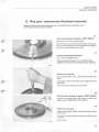
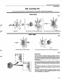
D. Timing gear chains, checking for wear
D1
A quick method of checking the timing gear chains is to remove the left-hand valve cover and check the position of
the chain tensioner. If in any doubt whatsoever, remove
the timing gear case and inspect carefully.
If the tensioner pin protrudes by 4 or more notches (8 mm)
(0.31 5 in) the chains should be renewed.
Note! Excessively worn chains can cause low oil pressures, and engine damage may result.
55
Group 21 Engine
Timing gear chains, replacement
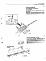
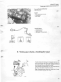
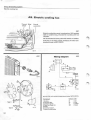
D. Timing gear chains, replacement
Special tools:
5103.5112
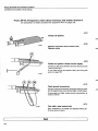
D2
The sprockets and also the strainers behind the belt tensioners must be replaced if the chains are nenewed.
The following parts should be changed from early to late
types:
- chain tensioners
- straight chain dampers
- bent chain dampers
Late type chain tensioners may only be used with late type
chain dampers.
1 Bent chain damper —
2 Chain tensioner
3 Straight chain damper.
Early type
mm (in)
Late type
mm (in)
without oilway
0 = 0.4
0.016
L = 174
6.85
with oilway
0 = 1.2
0.0472
L = 220
8.66
Note! On early manufactured B27 engines (up to middle
of 1976) a bent chain damper with a small mounting was
used.
When replacing an early type bent chain damper with a late
type, the bolts, washers and spacers must be replaced
with late types as well.
In addition the two support faces in the timing gear case
must be ground down, see fig. This is to provide room for
the new wider dampers.
Grind down 5 mm (0.2 in)
Grind level
135076
56
Group 21 Engine
Timing gear chains, replacement
D3
Disconnect battery earth lead
Both at the battery and the timing gear case.
B 27/28A
D4
Remove carburettor baseplate retaining screws
from intake manifold
Place the carburettor plus baseplate and the air filter on the
intake manifold.
Plug the hole in the intake manifold.B 27/28E
F
D5
Remove air filter and preheating hose (where
fitted)
D6
Drain coolant
Open the drain tap on the left-hand side of the cylinder
block. A hose can be connected to the drain tap to assist
collecting the coolant.
D7
Remove:
- radiator and hoses
- fan shroud.
Cars with automatic transmission: counterhold the nipples
on the oil cooler to prevent damage.
57
Group 21 Engine
Timing gear chains, replacement
Cars with air conditioning
Operation D8
D8
Detach and move aside compressor.
Remove rear compressor mounting bracket.
Attach the compressor to the right bonnet/hood hinge.
Mote! Do not slacken any of the refrigerant hoses otherwise the complete system will have to be evacuated and
filled with new refrigerant.
D9
Remove valve covers
It may be necessary to remove the air and vacuum pumps
from the left-hand valve cover.
D10
Remove:
-
cooling fan
splash guard
drive belt for power pump and alternator
power pump and mounting bracket. Hang up pump with
a wire so that it is not in the way.
D11
Turn crankshaft to overlap position for No. 1
cylinder
The mark " 1" on the pulley should align with the zero-mark
on the timing scale. The rocker arms for No. 1 cylinder
should not have clearance.
Note! There are two notches, 1 = TDC cylinder 1 and 2
= TDC cylinder 6.
58
Group 21 Engine
Timing gear chains, replacement
D12
Lock flywheel
Remove the cover plate on the left-hand side of the flywheel casing (RHD vehicles = right side).
Fit locking sector 5112 to the upper bolt (RHD vehicles =
lower bolt).
D13
Remove crankshaft pulley
36 mm socket
Take care that the key on the crankshaft does not fall out.
Remove locking sector 5112.
D14
Remove timing gear case
Plug the hole in the oil sump with paper.
D15
Slacken camshaft centre bolts
Allen key 10 mm.
If necessary use a screwdriver as a counterhold.
D16
Slacken timing gear chains
Turn each lock 1 / 4 turn anticlockwise and push in the piston.
D17
Remove:
-
oil pump sprocket and chain
chain tensioners and oil strainers
bent and straight chain dampers.
camshaft sprockets and chains.
132 589
59
.
Group 21 Engine
Timing gear chains, replacement
D18
Remove from crankshaft:
- outer sprocket
- spacer sleeve (early type) and key
- inner sprocket and key.
If necessary use a puller to remove the sprocket.
132 590
D19
Clean and check condition of chain tensioners and
dampers
Mote! Do not disassemble the tensioners. If the lock falls
out it will be necessary to renew the tensioner.
Make sure that the oil passages in the tensioners are not
blocked, and that the dampers are not worn or damaged.
If necessary install new parts.
Note! Chain tensioners and dampers should be changed to
later types, see page 56.
D20
Tap out timing gear case seal
D21
Clean gasket surfaces on:
- cylinder block
- timing gear case
- valve covers.
Use a wooden scraper.
132 592
D22
Oil crankshaft, sprockets and spacer sleeve
D23
Install:
- inner key
- inner sprocket. Note! The line on the sprocket should
face outwards
- spacer sleeve (early type)
- outer key
- outer sprocket.
132 593
60
Group 2 7 Er/a/'ne
r/m/rTfif #ear c/73/>?s, replacement
D24
Install:
-
new strainers in cylinder block
chain tensioners
straight chain dampers
bent chain dampers. Apply locking fluid
(P/N 116 1053-2) to bolts.
D25
lb!
Set crankshaft and left-hand camshaft
':--:-.
/^»
&3
lr
Ill
The key in the crankshaft should point towards the lefthand camshaft.
The groove in the camshaft should point upwards and the
rocker arms for No. 1 cylinder should not have clearance.
:;;:.., "hi^d--;
132 595
D26
Install left-hand camshaft chain and sprocket
Place the chain on the camshaft sprocket, with the mark
on the sprocket between the two marks on the chain.
Place the chain on the inner crankshaft sprocket, with the
mark on the chain opposite the mark on the sprocket.
Stretch the chain on the pulling side (the side against the
straight chain damper).
Position the camshaft sprocket. Make sure that the
sprocket fits in the groove in the camshaft.
Install the centre bolt.
•iJiiaa
m
m
^
D27
Set crankshaft and right-hand camshaft
Install the crankshaft nut. Turn the crankshaft clockwise so
that the key points directly downwards.
mm
m
w
I
The groove in the camshaft should point outwards, see
fig., and the rocker arms for No. 6 cylinder should not have
clearance.
%
-*•"""'
61
Group 21 Engine
Timing gear chains, replacement
D2S
Install right-hand camshaft chain and sprocket
Place the chain on the camshaft sprocket, with the mark
on the sprocket between the two marks on the chain.
Place the chain on the crankshaft sprocket, with the mark
on the chain opposite the mark on the sprocket.
Stretch the chain on the pulling (the side against the
straight chain damper.)
Install the camshaft sprocket. Make sure that the sprocket
fits in the groove in the camshaft. If necessary rotate the
crankshaft slightly.
Install the centre bolt.
D29
Tighten both camshaft centre bolts
Tighten to a torque of 70-90 Nm (52-66 ft. lbs.). Use a
screwdriver as a counterhold, placing it between two cogs
on the sprocket without holes.
I;
B 132 599
D30
Turn locks 1 / 4 turn clockwise
D31
Set chain tension
Turn the crankshaft round twice.
Remove the crankshaft nut.
Mote! The key in the crankshaft should point upwards to
prevent it from falling out of its groove.
When the crankshaft has been rotated the marks for the
chains and sprockets do not coincide. It is necessary to rotate the crankshaft a large number of turns to obtain the correct position.
D32
Install chain and sprocket for oil pump
Apply locking fluid (P/N 116 1053-2) to the bolts.
62
Group 21 Engine
Timing gear chains, replacement
D33
Remove protective paper. Install
timing gear case
Use new gaskets.
Smear the four lower bolts with locking fluid P/N
116 1056-5.
Tightening torque 10-1 5 Nm (7-11 ft. lbs.).
Clamp the wiring harness to the side of the timing gear
case.
D34
Install new seal in timing gear case
Grease the seal. Use drift 5103.
D35
Install crankshaft pulley
Fit locking sector 5112 to the flywheel casing at the lower
bolt (RHD-vehicles = upper bolt.)
Make sure that the key does not fall out.
36 mm socket.
Tighten the nut to the correct torque, see left.
Note! There are two different types of nuts.
D36
Install cover plate on flywheel casing
Remove locking sector 5112.
45 mm
If necessary adjust valve clearance, see B7-10, page 30.
160-180 Nm 2 4 0 - 2 8 0 Nm
(118-133 ft. lbs.)
(177-206 ft. lbs.)
D37
Cut gasket for timing gear case
Cut flush to the cylinder block.
.
D38
Install valve covers
Use new gaskets. Apply sealing agent (P/N 116 1026-8)
to a few places to secure the gaskets.
Tighten to a torque of 10-15 Nm (7-11 ft. lbs.)
To ensure that the junction between the valve cover, cylinder block and timing gear case is fully leak-proof, a thin coat
of silicone (P/N 116 1048-2) can be applied to the joint.
Note! Do not use too much silicone otherwise it may enter
the lubrication system and block the oil channels.
63
Group 21 Engine
Timing gear chains, replacement
D39
Close drain tap in left-hand side of cylinder block
D40
Install:
-
power pump bracket
power pump
cooling fan
drive belts for alternator and power pump
splash guard.
D41
Install parts on valve covers
Reconnect any hoses and wires which have been disconnected.
Use a new O-ring (gasket) for the vacuum pump (if removed). Make sure that the pump shaft meshes on top
of the camshaft.
Cars with air conditioning
Operation D42
D42
Install:
- compressor rear bracket
- compressor
- drive belt, to correct torque
D43
Install fan shroud and radiator
Reconnect all hoses and wiring.
Cars with auto-gearbox: connect oil tubes to oil cooler.
Counterhold the nipples on the cooler to prevent damage.
64
Group 21 Engine
Timing gear chains, replacement
B
27/28A
D44
Install carburettor + baseplate, and air filter
Use a new O-ring. Tightening torque 10-15 Nm
(7-11 ft. lbs.).
Reconnect hoses, linkages and wiring.
B27/28E, F
D45
Install air filter and pre-heating hose
(if equipped).
D46
Reconnect battery
Reconnect earth lead to timing gear case as well.
D47
Fill with coolant. Warm-up engine and check
Top-up if necessary.
D 48
D48
Check/adjust:
- ignition timing
- idle speed and CO-content.
CO
rpm
^
65
Group 21 Engine
Camshaft/rocker
arms,
replacement
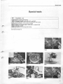
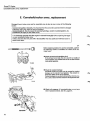
E. Camshaft/rocker arms, replacement
Damaged (worn) rocker arms and/or camshafts may be due to one or more of the following
causes:
- Incorrect oil quality or viscosity. It is important that the correct oil is used and that it is changed
sufficiently often with regard to driving conditions.
- Contaminated oil. May be caused by camshaft grindings, coolant or petrol/gasoline, etc.
- Insufficient oil supply to the rocker arms.
It is absolutely essential that the engine is cleaned thoroughly before replacing damaged
or worn camshafts/rocker arms.
If this is not done the new parts will in all probability wear out quickly and will have to be replaced once again.
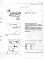
E1
Before replacing rocker arms and/or camshafts, perform
the following checks to establish the cause of the damage/wear:
• Check oil level and condition of oil
If the oil level is too high, the oil is too thin or smells of
petrol/gasoline, it is possible that the oil has been diluted
with petrol/gasoline.
114 922
• Check for coolant leakage
Camshaft/rocker arm wear may be caused by coolant
leakage via the cylinder head gaskets. The coolant reduces the ability of the oil to lubricate.
Coolant leakage can usually be detected by oil in the coolant. Look at and smell the coolant in the expansion tank.
114 923
Check oil pressure (if camshaft/rocker arms have
been replaced before). See N1, page 87.
66
Group 27 Engine
Camshaft/rocker
arms, replacement
Working procedure
E2
Flush engine clean
Change the engine oil and filter.
Warm-up the engine approx. 10 minutes.
Drain the oil and remove the filter.
E3
Replace camshafts/rocker arms
Remove the cylinder heads, see C1-25, page 32.
Replace necessery parts. Lubricate the parts well before
installation.
Install the cylinder heads, see C53-92, page 46.
Note! If there is a coating of carbon waste deposits on
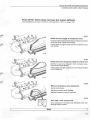
the valve casing or timing gear case, or if it is a repeat replacement, the valve casing, timing gear case, oil
sump/pan and oil strainer must be removed and thoroughly cleaned.
r
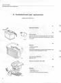
Different types of camshafts. Part number stamped
on end.
E4
Early type
Late type
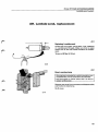
Check overflow/relief valve
If an early type valve (without filter) is fitted, replace it
with a new type, (with filter). See 01-5, page 90.
Late type valves introduced on:
Engine type
B27A
B28A
B27E
B28E
B27F
B28F
Engine number
None
1143 — •
76992 — *
All
None
11169 — •
E5
Install N E W oil filter and fill with N E W engine oil
67
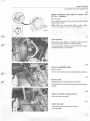
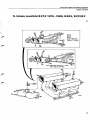
Group 21 Engine
Crankshaft pilot bearing,
replacement
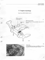
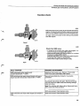
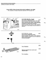
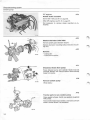
F. Crankshaft pilot bearing, replacement (gearbox removed)
Pilot bearings are fitted only on vehicles with manual gearboxes
Special tools: 4090
1426 or 1801 +5101 (depending on diameter of bearing)
5113 or 2484 or 5111 (depending on type of gearbox)
F1
Remove clutch pressure plate and driven plate
Inhex 6 mm.
Slacken the pressure plate retaining bolts crosswise, a few
turns at a time, to avoid distorting the plate.
F2
Remove bearing
Use extractor 4090. Clean the hearing seat.
F3
Install bearing
Tap in the bearing until it abuts the crankshaft.
There are two types of bearings:
Early type = inner diameter 17 mm (0.669 in). Use standard handle 1801 and drift 5 1 0 1 .
Late type = inner diameter 1 5 mm (0.590 in). Use drift
1426.
F4
Install driven plate
Turn the plate so that the hub faces outwards, away from
the flywheel.
There are different centering drifts for the different types of
gearboxes:
M 50/51 = drift 5113
M 4 5 / 4 6 early type = drift 2484
M 4 5 / 4 6 late type = drift 5111
F5
Install pressure plate
34 981
Tighten the retaining screws crosswise, a few turns at a
time, to avoid straining the plate.
Inhex 6 mm.
68
Group 21 Engine
Ring gear, replacement
G. Ring gear, replacement (flywheel removed)
Applies to vehicles with manual gearboxes only. On automatic drive vehicles the carrier
plate is replaced along with the ring gear.
G1
Heat new ring gear to approx. 2 3 0 ° C (450°F)
Use an oven or an oxy-acetylene flame.
r
If you intend to use an oven begin heating the new ring gear
now. If you are going to use oxy-acetylene the ring gear
should be heated just before it is fitted.
G2
Drill a hole between t w o cogs
Use a 10 mm (0.394 in) drill.
The hole should be approx. 9 mm (0.394 in) deep.
Caution! Do not drill into the flywheel (causes imbalance).
G3
Remove old ring gear
Set up the flywheel in a vice, use soft jaws to prevent damage.
If necessary crack the ring gear with a chisel above the
drilled hole.
Clean the contact surfaces on the flywheel.
G4
Heat up new ring gear to approx. 2 3 0 ° C (450°F)
Check the temperature with solder (40% tin, 60% lead).
Solder melts at 220-230°C. (430-450°F).
G5
Install new ring gear
Position the ring gear. Note! The bevelled side must face
the flywheel.
If necessary use a brass drift to tap down the ring gear until
it bottoms.
Leave to cool.
69
Group 21 Engine
Crankshaft front seal, replacement
H. Crankshaft front seal, replacement
Special tools: 5103, 5112
H1
Disconnect battery
H2
Drain coolant
Open the drain tap on the left-hand side of the cylinder
block. A hose can be connected to the drain tap to collect
the coolant.
H3
Remove:
- radiator and hoses
- fan shroud
Cars with auto-gearboxes: counterhold the nipples on the
oil cooler to prevent damage to the pipes.
Cars with air-conditioning
Operation H4
H4
Remove compressor drive belt
H5
Remove:
- cooling fan
- engine splash guard
- drive belts for power pump and alternator.
70
Group 21 Engine
Crankshaft front seal, replacement
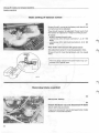
H6
Rotate crankshaft until engine is approx. 20°
B . T . D . C . , cylinder 1
36 mm socket.
This is done to prevent the key on the crankshaft falling
down into the sump.
Note! There are two timing marks on the pulley,
1 = T.D.C. cylinder 1 and 2 = T.D.C. cylinder 6.
r
H7
Lock flywheel
Remove the cover plate on the left-hand side of the flywheel cover (RHD-vehicles = right-hand side).
Lock the flywheel with locking sector 5112 at the upper
bolt (RHD-vehicles = lower bolt).
H8
Remove crankshaft pulley
36 mm socket.
Take care that the key on the crankshaft does not fall out.
H9
Remove seal
Carefully lever out the seal with a screwdriver.
The mating surface of the timing gear case must not be damaged.
H10
Clean and check mating surfaces
Both the pulley and casing
H11
Install new seal
Pack grease between the lips of the seal
Use drift 5103.
71
Group 21 Engine
Crankshaft front seal, replacement
H12
Install crankshaft pulley
Take care that the key on the crankshaft does not fall out.
Transfer locking sector 5112 to the lower hole (RHDvehicles = upper hole).
Install the nut and tighten to the specified torque. See left.
Note! There are two different types of nuts.
36 mm socket.
H13
g
Install cover plate on flywheel casing
40mm I
Remove locking sector 5112.
45mm II
H14
/ /
/ /
123 099
Close drain tap in left-hand side of cylinder block
160-180 IMm 2 4 0 - 2 8 0 Nm
(118-133 ft. lbs.)
(177-206 ft. lbs.)
H15
Install:
- cooling fan
- drive belts for the power pump and alternator. Set to the
correct tension.
- cars with AC: compressor drive belt to correct tension
- engine splash guard.
H16
Install fan shroud and radiator
Reconnect hoses and wiring for electric cooling fan (where
fitted).
Cars with auto-gearbox: reconnect all tubes to the oil cooler. Counterhold the nipples to prevent damage.
H17
Reconnect battery.
Fill with coolant
H18
135 041
Warm-up engine and check
Top-up with coolant if necessary.
72
Group 21 Engine
Crankshaft rear seal, replacement
H. Crankshaft rear seal, replacement (gearbox removed)
Special tools: 1801,5112, 5953
5113 or 2484 or 5111 (depending on type of gearbox)
"*
Manual gearboxes
Operation HI9
H19
Remove pressure plate and driven plate
Inhex 6 mm.
Slacken the pressure plate retaining bolts crosswise
to avoid distorting the plate.
H20
Remove flywheel and carrier plate
Lock the flywheel with locking sector 5112.
H21
Remove crankshaft rear seal
Lever out the seal with a screwdriver. Take care not to damage the sealing surfaces in the holder and crankshaft.
H22
Clean and check sealing surfaces
Both in the holder and crankshaft.
H23
Install new seal
Assemble standard handle 1801 and drift 5953.
Lubricate the seal and groove. Pack grease between the
sealing lips.
Place the seal on the drift, see fig.
Tap in the seal until the drift abuts the crankshaft.
73
Group 21 Engine
Crankshaft rear seal, replacement
H24
Install flywheel and carrier plate
The flywheel can only be fitted in one position. The screw
holes are assymetrically located.
Use new bolts.
Tighten to a torque of 45-50 Nm (33-37 ft. lbs.). Use
locking sector 5112 to lock the flywheel.
Automatic
gearboxes
Note the position of the support plates. The inner plate
must be turned so that the bevel edge faces forwards.
_
-G
y
I
Manual gearboxes
Operation H25
r 'j
• ' i
-ij
Install driven plate and pressure plate
-
•J . /
(
\
H25
^7%H
Turn the driven plate so that the hub faces outwards, away
from the flywheel.
/ H ,151131 p>]H
M 50/51 = drift 5113
M 4 5 / 4 6 early type = drift 2484
M 4 5 / 4 6 late type = drift 5111
3
- L .'1
There are different centering drifts for the different types of
gearboxes:
* j
| ^ ^ H
|
134 981
Tighten the pressure plate retaining bolts crosswise, a few
turns at a time, to avoid distorting the plate.
Inhex 6 mm.
74
Group 21 Engine
Engine mountings
K. Engine mountings
Special tools: 5006, 2x5033,
2x5115
Pad
(early manufactured
vehicles only)
K1
Removing/installing
Right-hand
drive
The mountings are removed/installed along with the
brackets.
135 047
K2
Lifting tool
Use beam 5 0 0 6 , two support rails 5033 and two lifting
hooks 511 5 to off-load the engine mountings.
77
Group 21 Engine
Replacement of engine
L Replacement of engine
Operations L1-4
Special tools: 2810, 2x5100
The engine is removed and installed with the gearbox attached
s .
134 983
LI
Preparing engine for removal
Remove:
-
bonnet/hood
lead from battery
air filter + preheating hose
radiator and fan shroud
- AC compressor.
Hang the compressor from the right-hand bonnet/hood
hinge. Caution! Do not disconnect any refrigerant
hoses.
- front exhaust pipe from branch pipe (not vehicles with
coupled exhaust system)
- disconnect wiring, water hoses, vacuum hoses and
cables.
$1P
135 048
78
Group 27 Engine
Replacement of engine
L2
From beneath engine
Remove:
- splash guard
- power steering pump. Note! Do not'disconnect any of
the hoses. Hang the pump from the body with a wire
- engine mounting retaining bolts in the front crossmember.
L3
Remove parts from gearbox
Remove:
- mounting clamps for the front exhaust pipe
- (cars with coupled exhaust system): uncouple
- (manual gearboxes): clutch master cylinder and gear
lever
- (auto gearboxes): selector control linkage from gearbox
- speedometer drive cable
- propeller shaft
- gearbox crossmember. Off-load the gearbox with a garage jack
- disconnect wiring.
Manual gearb
Auto gearbox
L4
Lift out engine
Use lifting cradle (2x5100 and 1 X2810).
Working procedures after repositioning the engine, see
L5-13, page 80.
«,->
134 984
79
Group 2 7 Engine
Replacement of engine
Working procedures after repositioning engine
Operations L5-13
Special tool: 5098
Manual gearboxes
L5
Adjust bracket for reverse gear detent. Install rubber gaiter/bellows.
Engage 1st gear.
Adjust the clearance between the bracket and gear lever.
Correct clearance = 0.5-1.5 mm. (0.02-0.06 in)
Use a feeler gauge.
Re-tighten the retaining screws.
Engage 2nd gear and re-check the clearance.
Install the rubber gaiter/bellows.
Automatic
gearboxes
L6
Check/adjust gear selector linkage
1. Make sure that the clearance from position " D " to the
stop is approximately the same as from position " 2 " to
the stop.
2. Adjust the length of the selector rod if necessary.
Rough adjustment: turn the adjuster at the rear of the
selector rod.
Fine adjustment: turn the serrated sleeve (max. visible
thread length = 35 mm = 1.377 in)
Extending the rod reduces the clearance in position " D"
and increases the clearance in position " 2 " .
After adjustment: move the selector lever to position
" 1 " and then back to "?". Re-check according to
item 1.
Automatic
gearbox
L7
Fill engine oil and coolant
Engine oil capacity 6.5 litres (6.9 US qts) (including oil filter). Add an additional 0.5 litre (0.5 US qts) if the engine
has been disassembled and the crankcase is completely
dry.
Cooling system capacity 10.9 litres (11.5 US qts). Set the
dashboard heater control to max. heat.
Automatic
gearboxes
L8
Check oil level, top-up if necessary
The engine must be running. Engage either " N " or " P " .
117 996
80
Group 21 Engine
Replacement of engine
L9
Check engine
Start the engine and warm-up.
Check for oil and coolant leakages.
Top-up if necessary.
L10
Adjust throttle cable
The drum must strike the stop on return. The cable must
be taut but must not affect the position of the drum.
At full throttle the drum must strike the other stop.
Automatic
gearboxes
L11
Adjust throttle cable
Press the accelerator pedal to the floor. Note! Do not adjust the linkage by hand otherwise the setting will be incorrect.
At full throttle the distance from the cable sleeve to the clip
must be 50.4-52.6 mm (1.98-2.07 in)
L12
Check/adjust:
- ignition setting
- idle speed and CO-content
if engine has been disassembled
L13
Re-tighten cylinder head bolts
Note! The engine must have been warmed-up and allowed to cool for 30 minutes before re-tightening the
bolts.
Follow the procedure below, one bolt at a time.
A. Slacken the bolt
B. Tighten to a torque of 1 5-20 Nm (11-15 ft. lbs.).
C. Angle-tighten to 113-117°. Use protractor 5098.
132 578
81
Group 21 Engine
Removing parts
Removing parts from engine
Operations L14-17
Special tools: 2520, 2903, 5099
L14
Remove:
- starter motor
-gearbox. Note! Auto: do not forget the torque converter
bolts
- oil filter. Use wrench 2903
- drain taps for coolant.
L15
Attach fixture 5 0 9 9 to engine
The engine is held in position by means of two bolts
screwed into the flywheel casing, and one bolt in each of
the drain tap screw holes.
L16
Place engine on stand 2 5 2 0
Remove the lifting cradle.
L17
Remove remaining parts
82
Group 21 Engine
Installing parts
Installing parts on engine
Operations
LI8-24
Special tools: 1426 or 1801 + 5101 (depending on diameter of pilot bearing)
5113 or 2484 or 5111 (depending on type of gearbox)
5112
Only operations where special care must be exercised are dealt with in this section.
LI 8
Always use:
- new gaskets and seals
- new bolts for flywheel/carrier plate
- new crankshaft pilot bearing (manual gearboxes).
^355ny
L19
Check, replace if necessary:
13S0S2
- (E/F-engines) rubber seals at the injectors. The seals
may have become oval and cause: air leakage, erratic idling, etc.
- water and vacuum hoses
- clutch + release bearing
L20
Flywheel (manual), carrier plate (auto)
45-50Nm
New bolts. Tighten to a torque of 4 5 - 5 0 Nm (33-37).
/ ^
Use locking sector 5112 to secure flywheel.
Automatic
5112
Automatic: Note position of support plates. The inner
plate must be turned, bevel side forwards.
: -csfj
j f ^
I
I
135053
1426
1801+5101
L21
Crankshaft pilot bearing
Tap in the bearing until it abuts the crankshaft.
There are two types of bearings:
Early type = inner diameter 17 mm (0.669 in) Use standard handle 1801 and drift 5 1 0 1 .
Late type = inner diameter 15 mm (0.590 in). Use drift
1426.
83
Group 21 Engine
Installing parts
122
Driven plate, pressure plate
Turn driven plate so that the hub faces outwards, away
from the flywheel.
There are different centering drifts for the different gearbox
types:
M 5 0 / 5 1 = drift 5113
M 4 5 / 4 6 early type = drift 2484
M 4 5 / 4 6 late type = drift 5111
135055
Tighten the pressure plate retaining screws crosswise, a
few turns at a time, to avoid distorting the plate.
r
123
Distributor
Set engine to T.D.C. cylinder 1 firing position. Make sure
that cylinder 1 intake valves are at the firing position and
not the overlap position.
Turn the rotor so that it points towards the clip for the distributor cap.
Install the distributor. When installed, the rotor should
point towards the mark on the distributor body.
A Before installation
B After installation
124
Gearbox
Check that the guide pins in the cylinder block protrude by
10-12 mm. (0.4-0.47 in)
If tubular pins are installed replace with solid opes (P/N
1232544-5). Apply locking fluid.
135057
Automatic
gearboxes
Lightly grease the torque converter guide and the equivalent hole in the crankshaft.
45 Nm
84
Tighten the torque converter retaining bolts to 45 Nm
(4 bolts) = 35 ft. lbs.
/S&*'
Group 22 Lubricating
system
Contents
Group 22 Lubricating system
Engine oil, oil filter
Oil pressure, check
check/remedial action for low pressures
Overflow valve (at oil filter),
replacement to late type
Oil pump, removal/installation
cleaning/inspection
Operation
Page
M1-2
N1
N2-8
86
87
87
01-5
P1
P2
90
92
92
85
Group 22 Lubricating
system
Engine oil oil filter
M. Engine oil, oil filter
Special tool: 2903
Ml
Engine oil
The engine should be hot when changing the oil. Replace
the drain plug washer.
Oil capacity, excl oil filter
incl oil filter
Difference, max.-min
6.0 litres (6.3 US qts)
6.5 litres (6.9 US qts)
1.0 litres (1.0 US qts)
If the engine has been disassembled and the crankcase is
completely dry add an additional 0.5 litre of oil.
Other markets
USA and Canada
Note! SE/CD-oils must not be used.
Type and grade
SF/CC
Viscosity:
Viscosity:
Type and grade
according to API Service-SF/CC
Temperature range
(stable ambient temperatures)
-30 -20
-22
i
-10
0
10
20
14
32
5068
T
SAE 1QW/30"
<
Temperature range
(stable ambient temperatures)
30
4 0 °C
30 -20
86
104 °F
-22
D
SAE 0 W 3 0 , 5W 30
SAE 15W 50
4
SAE 20W 50
<f
32
14
SAE 0 W 3 0
<
n
<^
-10
_! .
i_
SAE 10W/40
<c
.. according to API Service-SE/CC or
X
c
!>
20
30
4 0 °C
50
6,8
86
104 °F
5W 30
SAE 1QW/30
r^—i
SAE 1QW#Q:
<
z>
SAE 15W 50
<^
SAE 30
10
SAE 20W 50
^
SAE 30
c
SAE 4 0
SAE 1 5 W / 5 0 or SAE 20E/50 oils are recommended for use in extreme driving conditions
which involve high oil consumption and high oil temperatures, e.g. mountain driving with frequent decellerations or fast motorway driving. (Note however the lower temperature limits.)
I1
M2
•2903M
Oil filter
J^A
JBL\
Use strap wrench 2903 to remove the filter.
^-—J|w o\
nfl
See the installation instructions on the cartridge.
2j
j «
M l*m
w^^jj^
m&m
w
M§nSu
m% \ V V \ V \ t ' MH | 116 325
86
For replacement of filter only, add 0.5 litre (0.5 US qt) of
engine oil.
Group 22 Lubricating
system
Oil pressure, check
N. Oil pressure, check
A/7
Use the output on the left-hand side of the engine, in front
of the oil filter, to measure the oil pressure. If the pressure
is measured anywhere else, the results will be invalid.
The adapter (P/N 464592-5) can be used for B20 and
B1 7-B23 engines.
With a hot engine and new oil filter, the oil pressure should
be:
1 5 r/s (900 r/min)
50 r/s (3 000 r/min)
min
0.1 MPa (14.2 psi)
0.4 MPa (57 psi)
* Correct type, grade and viscosity
Low oil pressures
Carry out the following checks/remedies
N2
Check oil level
Cars with GT-instruments
Operation N3
N3
Check that oil pressure sender is correctly installed
The oil pressure sender for GT-instruments should be located on the port on the left-hand side of the engine (in
front of the oil filter).
The adapter (P/N 464592-5) must be used if a correct fit
is to be obtained.
Note! The standard oil pressure sender must be left installed. If this sender is replaced (by an incorrect one or a
plug) one of the oilways in the cylinder block is exposed and
the oil pressure will be too low.
N4
Check oil flow to all rocker arms
Disconnect the lead from terminal 1 5 on the ignition coil
(safety precaution).
Crank the engine and check the flow of oil from the rocker
arm jets. Ample oil should flow and no air bubbles should
be present.
Different fault symptoms:
Air bubbles, see N5-6.
Poor oil flow from all rocker arms, see N7-8.
Q
114 931
87
Group 22 Lubricating
system
Oil pressure, check
AIR BUBBLES IN OIL
Operations N5-6.
N5
Air bubbles in oil indicates that there is leakage from the intake side of the oil pump.
The reason may be leaking O-rings, either between the engine block and sump, or between the sump/pan and oil
strainer.
114 932
Guide sleeve
On early engine versions the guide sleeve between the cylinder block and sump/pan may have fallen out. In such cases the oil will leak from the upper O-ring.
New cars are fitted with a collar in the sump/pan which
prevents the sleeve from falling out.
Collar
-M
N6
If guide sleeve has fallen out:
It is possible to replace the upper O-ring and secure the
guide sleeve from below.
- remove pieces of old O-ring. Clean the oil strainer, both
internally and externally
- Carefully clean the oilway
- Install a new O-ring. Use a bent screwdriver to position
the O-ring.
- Install a new guide sleeve. Use locking fluid P/IM
1161057-3
- install a new oil strainer and a new O-ring
- install remaining parts and add engine oil.
132 834
88
Group 22 Lubricating
system
Oil pressure, check
POOR OIL FLOW AT ALL ROCKER ARMS
Operations N7-8
Indicates internal leakage or poor pump capacity
N7
Check timing gear chains for wear
If the chains are worn the chain tensioners will have
reached their outmost position. Oil will leak past the pistons in the chain tensioners and the oil pressure will be too
low.
Use a torch and assess the condition of the chain tensioners.
Replace the chains if the pin in the tensioner protrudes by
more than 4 teeth (8 mm = 0.31 5 in). See D2-48, page
56.
N8
Check:
- that oil strainer is not blocked
- oil pump and relief valve
- that oil pump shaft is firmly secured to cylinder block.
89
Group 22 Lubricating
system
Relief valve, replacement
O. Relief valve
Replacement from early to late type
(oil filter removed)
Early type
Late type
Early type = without filter
Late type = with filter
Late type valves are introduced on:
Engine type
B27A
B28A
B27E
B28E
B27F
B28F
Engine No.
None
1143—•
76992
•
All
None
11169
•
Required materials:
IHbD/ 'I M , ih114 925
Description
Qty
Part number
Valve
Seal
Filter
Washer
1
1
1
1
1218056-8
1218054-3
1218175-6
1218055-0
01
Withdraw old valve from engine block
Use a pair of pliers or a screwdriver. Take care not to damage the oil filter mating surface.
02
114 926
Clean hole
Remove dirt, etc. Use a knife or scraper.
Clean thoroughly. Caution I Do not use compressed air. Dirt,
oil deposits, can be blown into the oilways.
90
Group 22 Lubricating system
Relief valve, replacement
03
Install new parts
Install the valve, with the spring facing inwards.
114 927
04
Press on washer
Use a 11 mm (inner dia) socket.
114 928
05
Secure washer
Use a drift to make three small notches around the washer.
114 929
91
Group 22 Lubricating
system
Oil pump
P. Oil pump
PI
Removing/installing
Timing gear case,
removing, see D3-14, page 57.
installation, see D20-21, 3 3 - 4 7 , pages 60 and 62.
Clean all parts before installation. Also clean the housing in
the cylinder block.
Oil the housing, cogs and shafts.
Tightening torque retaining bolts, oil pumpcylinder block =
10-15 Nm (7-11 ft. lbs.)
Smear locking fluid (P/N 1161053-2) on the bolts for the
oil pump sprocket.
P2
Cleaning/inspection
The oil pump is supplied as a complete unit (i.e. cover, cogs
and relief valve). Spare parts are however available for the
relief valve.
132 639
Clean and inspect all parts. If in doubt, check tolerances,
see below.
Specifications m m (in)
Axial clearance
Radial clearance between tooth top and pump housing
(excluding bearing clearance)
Backlash (excluding bearing clearance)
Bearing clearance, drive shaft
idler shaft
Relief valve spring length
unloaded
under load of 88.3 N (20 lbs.)
92
0.025-0.084
0.0009-0.0033
0.110-0.185
0.17-0.27
0.015-0.053
0.015-0.051
0.0043-0.0072
0.0066-0.0106
0.0006-0.0021
0.0006-0.0020
89.5
56.5-60.5
3.52
2.22-2.38
Group 25 Intake and exhaust
systems
Contents
Group 25 Intake and exhaust systems
Intake manifold
B27/28A
B27E1975-1978
1979-1980
B 28 E,B 27/28 F
Operation
Q1-8
R 1-2
S1-9
S1-9
Page
94
96
97
97
Exhaust manifold
T 1 -2
101
Exhaust manifold a n d silencers
u 1 -2
103
Crankcase ventilation
vi
103
Catalytic converter
X1-3
104
Pump
Y1-7
105
Pulsair system
z 1 -4
107
On/off system
general
testing
fault symptoms
AA1-3
AA 4 - 5
AA 6
108
109
109
Stepless system, type 1
general
testing
fault symptoms
AB 1-3
AB 4 - 5
AB 6 - 1 2
110
111
111
Stepless system, type 2
general
testing
fault symptoms
AC 1 - 3
AC 4 - 5
AC 6 - 1 0
114
115
115
A D 1
117
AD 2
117
AE 1
118
AE 2
118
Exhaust gas recirculation (EGR)
J^*v
/•^
Cleaning of EGR system (all types)
Adjusting dashboard indicator lamp (F-engines only)
Installing new type pipe for EGR
general method
required parts
B 27 E 1979-1980
B 27 F 1976-1978
Lambda-sond system
Location of components
Connection of vacuum hoses
Wiring diagram
General instructions
Fault symptoms
Fault tracing (checking system)
Installing pressure differential switch
(B28F USA+Canada 1980-1981)
Replacement of Lambda-sond
Altitude adjustment (USA only)
AE 3 - 1 2
119
AE 13_26
121
A
F 1
F 2
A
F 3
AF 4 - 6
AF
7
A
F 8-43
124
125
125
126
127
127
AG 1-10
AH 1 - 2
AJ 1 - 4
136
139
140
A
93
Group 25 Intake and exhaust
Intake
systems
manifold
Q. Intake manifold B 27/28 A
Q1
Cover plate
Intermediate piece B 27 A1976
Replacement parts incorporate idle
channel.
On installation, solenoid valve hole
^must be plugged (P/N 1266 494-2).
Turn gasket right way.
Vent hole must not be
blocked.
Inlet funnel
B 28 only
136 322
* All right hand drive vehicles.
Only late type on left hand drive
vehicles.
Heat chamber
Intake manifold must be removed to
replace gasket or chamber (see Q8,
page 95).
Early type
Throttle housing
Q2
Checking
Ensure smooth operation of throttle and position of
lever at different engine temperatures and speeds.
Closed = cold engine and at idle.
Open = warm engine at speeds above idle. Throttle
opening depends on power output.
132 725
Q3
Replacement
Exhaust pipe
The exhaust pipe must be disconnected from branch
pipe to obtain access to throttle housing. Also necessary to unscrew mounting bracket near gearbox so
that exhaust pipe can be guided to rear.
Use new gaskets when installing throttle housing. Install gasket with reinforced metal edge facing branch
pipe and throttle housing respectively.
94
Group 25 Intake and exhaust
systems
Intake
manifold
Q4
Q5
Removing intake manifold
Installing intake manifold
Three working procedures for removing intake
manifold are described below. Choose method
which suits purpose of repair.
Use new O-rings and gaskets. Tightening torque
10-15 Nm (7-11 ft.lbs.).
As a safety precaution, always disconnect battery
before starting repair.
For connection of vacuum hoses see page 14.
After installation check/adjust:
- throttle controls
- idle speed and CO content.
Q6
Method 1 Replacing O-rings
Disconnect intake manifold and lift it up slightly to
obtain access to the O-rings.
Note! Tubes to Hot-spot must be disconnected from
rear edge of intake manifold.
Q7
Method 2 In connection w i t h removing cylinder
heads
Intake manifold must be removed complete with carburettor.
It will be necessary to drain the coolant.
Q8
Method 3 Removing intake manifold e.g. when
fitting a new Hot-spot gasket
Intake manifold can be removed without carburettor
and intermediate section.
It is not necessary to drain the coolant.
95
Group 25 Intake and exhaust
Intake
systems
manifold
R. Intake manifold B 2 7 E 1 9 7 5 - 1 9 7 8
Removing intake manifold
Intake manifold must be removed with air-fuel control
unit.
Disconnect battery prior to removal of manifold.
Clean all fuel line connections before disconnecting
pipes.
Disconnect (move to one side) wires, hoses and cables, identify if and as necessary.
Place wiring harness on panel above radiator.
Detach clips retaining distributor cap.
Remove intake manifold.
R2
Installing intake manifold
Install new O-rings.
Tightening torque 10-15 Nm (7-11 ft.lbs.).
Re-connect wires, hoses and cables.
For connection of vacuum hoses, see page 14.
After installation, check/adjust:
- throttle controls
- idle speed and CO content.
96
Group 25 Intake and exhaust systems
Intake manifold
S. Intake manifold B27E 1 9 7 9 - 1 9 8 0 , B28E, B 27/28 F
si
136 327
97
Group 25 Intake and exhaust
Intake
systems
manifold
Basic setting of balance screws
S2
Screws 2 and 3 are set at the factory and should not
normally need to be adjusted.
They should however be adjusted if lower part of air
flow sensor is replaced or if engine running is poor.
To adjust:
- screw in screws 2 and 3 fully.
- unscrew no. 2 for left bank (cylinders 1, 2, 3) 1 1/2
turns
- unscrew no. 3 for right bank (cylinders 4, 5, 6) 5.0
turns.
Note! B 28 F with constant idle speed system
Idle adjustment screw (1) must be screwed in fully.
Screws (2 and 3) must be tightened until the heads
shear.
Failure to shear adjustment screw heads may contravene USA Federal laws.
136 329
Removing intake manifold
S3
Disconnect battery
S4
Detach distributor cap and disconnect HT leads
Detach both clips (arrowed).
If cap is not removed it may be damaged when intake
manifold is removed/installed.
98
Group 25 Intake and exhaust
systems
Intake
manifold
S5
Disconnect front part of intake manifold
r
S6
Detach intake manifold w i t h air-fuel control
unit
Move hoses and cables to one side, disconnect as
necessary. Clean fuel line connections thoroughly
before disconnecting pipes.
Detach wiring and place harness on top of radiator
panel.
Remove intake manifold with air-fuel control unit.
Qgh^i
B 28 F1981
99
'
Group 25 Intake and exhaust
Intake
systems
manifold
Installing intake manifold
S7
Install intake manifold w i t h air-fuel control unit
Install new O-rings.
Tightening torque 10-15 Nm (7-11 ft.lbs.).
Connect wires, hoses and cables.
For connection of vacuum hoses, refer to page 14.
Attach distributor cap and re-connect HT leads.
S8
Install front part of intake manifold
S9
Check/adjust:
- throttle controls
- idle speed and CO content.
B 28 F1981
100
Group
25 Intake
and exhaust
Exhaust
systems
manifold
T. Exhaust manifold
Removing/installing
77
As a safety p r e c a u t i o n d i s c o n n e c t o n e of battery leads.
Exhaust s y s t e m m u s t be d i s c o n n e c t e d f r o m b o t h
b r a n c h pipes before exhaust m a n i f o l d can be
r e m o v e d . A l s o exhaust m o u n t i n g near g e a r b o x must
be r e m o v e d so t h a t t h e exhaust pipe can be m o v e d to
rear t o o b t a i n access to b r a n c h pipes.
Branch pipe s h o u l d be r e m o v e d / i n s t a l l e d w i t h air inlet
pipes or Pulsair s y s t e m pipes in p o s i t i o n (as applicable).
t, C
'CI
sn«e>—iG9
Reinforced metallic e d g e ^ —
Z~sr'
Gaskets
12
Several d i f f e r e n t t y p e s of b r a n c h pipe gaskets are in
use. Only late t y p e , s h o w n adjacent, is stocked by
Parts Dept.
Passage for air inlef
/Pulsair
136 335
Gaskets are s u p p l i e d in packs of t h r e e , a n d m u s t be
s e p a r a t e d b y c u t t i n g a n d not by f o l d i n g , or d a m a g e
may result.
Gaskets m u s t be i n s t a l l e d w i t h r e i n f o r c e d metallic
edge facing c y l i n d e r h e a d .
Gaskets b e t w e e n exhaust pipe a n d b r a n c h pipe must
be i n s t a l l e d w i t h r e i n f o r c e d m e t a l l i c edge facing
branch pipe.
t*__-£?
Branch pipe
Witt
Throttle housmcA'
t B 27/28 A
Exhaust pipe
/firs I
< ii
r^L ,'< II
Reinforced metallic
edge
'136 336
B 27/28 A Reinforced metallic edge
101
Group 25 Intake and exhaust systems
Exhaust pipe and silencer
U. Exhaust pipe and silencer
Type of exhaust system installed depends on market and model year. Shown below is the
exhaust system on B 28 F USA 1980.
>
136 337
General
Installation of complete system
U1
• Use new gaskets. Turn gasket metallic face against
manifolds. Steel face with raised edge should be
replaced only if damaged.
• Exhaust pipe should be inserted approx. 40 mm
(1.6 in.) into silencer.
• Clearance between exhaust system and body
should not be less than 20 mm (0.8 in.).
U2
Follow work sequence below to avoid tension in
system.
t-••;•>. •"-• -,
1*J2 V.
A k =
5*0 A / : .
'ANCCUY£S>, B.C. '
> J*«
102
!?-#».,
1. Unscrew retaining bolts A on mounting bracket gearbox.
2. Hang up and align complete exhaust system.
3. Tighten nuts B at front pipe - manifold.
4. Tighten catalytic converter C.
5. Tighten bolts D for mounting bracket - front pipe.
6. Tighten bolts A for mounting bracket - gearbox.
7. Tighten clamps E for silencer - pipe.
8. Tighten coupling F as applicable.
9. Check that system cannot strike body, adjust if
necessary.
Group 25 Intake and exhaust systems
Crankcase ventilation
V. Crankcase ventilation
Cleaning/checking
VI
• clean/check all hoses
• clean calibrated nipple
• clean oil filler cap and clean/replace strainer as
necessary.
B 27 E1975-1978
B 27/28 A
Calibrated
nipples
136 341
136 340
B 27 F1976-1978
Note! Modified crankcase ventilation system may
be fitted on some models, see B27F 1979.
B 27 E1979-1980
B 27 F1979
B 28 E/F
103
Group 25 Intake and exhaust systems
Catalytic converter
X. Catalytic converter
Part Number (P/N)
XI
Type of catalytic converter fitted to vehicle depends on
engine type, year model and market. Direction of flow
and part number are indicated on converter.
Direction of flow
X2
Some converters are attached to exhaust system by
pin studs and it is not necessary to replace converter if
one of studs is damaged. In such cases drill out
damaged stud and install nut and bolt.
X3
Efficiency of catalytic converter can be checked by
recording and comparing CO level before and after
converter.
136 344
104
>
Group 25 Intake and exhaust
systems
Air
z
pump
Y. Air pump
Y1
Diverter valve
J&^>
Air pump
Backfire valve
136 346
IMPORTANT
• Air pump must not be lubricated or dismantled but
instead replaced if defective.
• Never plug or obstruct the diverter valve outlet since
this can cause severe damage to air pump.
Checking air injection system
Operations
Y2-5
Y2
Check backfire valve
Disconnect hose from diverter valve and check function of backfire valve by alternately blowing and sucking on hose.
Y3
Check air pump a t t a c h m e n t and drive belt
Check drive belt for cracks, wear, etc.
Check security of air pump.
Plug end of divertervalve hose (safety precaution) and
start engine. Pump operates noisily especially when
cold.
136 348
105
Group 25 Intake and exhaust systems
Air pump
Y4
Check diverter valve
Diverter valve hose must be plugged prior to checking.
Run engine at idle and check that air is blown out of
port (A) on diverter valve.
Increase engine speed to about 50 r/s (3500 r/min) and
release throttle quickly. Air flow from (A) should stop
for a few seconds and air should be blown out of vent
holes (B) on side of valve.
If incorrect, check vacuum hose between diverter
valve and engine intake manifold before testing with a
new diverter valve.
Y5
Turn off engine and re-connect hose to diverter
valve
Replacing drive belt
Y6
If drive belt has snapped check function of backfire
valve. (A defective valve can cause belt to break off.)
128 519
Removing/installing air manifold
Y7
Air manifold should be removed/installed attached to
branch pipe.
136 334
106
Group 25 Intake and exhaust systems
Pulsair system
(Early
type
Late type
Z. Pulsair system
General
Z1
Disconnect and plug connections of Pulsair system
before checking/adjusting CO content otherwise
results will be false.
136 350
131626
Checking Pulsair system
Z2
Check:
- security of all connections
- hoses for leaks.
Z3
131 627
Check non-return valves
Disconnect hoses from upper non-return valve.
Start engine and hold hand above valve. It should be
possible to feel air being drawn into system and that
no exhaust gases are leaking.
Next check remaining two valves in same way.
Removing/installing air manifold
Z4
136 334
Air manifold should be removed/installed attached to
branch pipe.
107
Group 25 Intake and exhaust
Exhaust gas recirculation,
systems
on/off
system
AA. Exhaust gas recirculation (EGR)
ON/OFF system
Delay valve
(certain models only)
/ffiw*'
AA1
EGR system is fitted on following engines:
B 27 F 1976 automatic Canada and USA Federal
1977 automatic Canada
B 27 E1980 Sweden and Australia
B 28 E1981-1982 Sweden and Australia
Cleaning EGR system
AA2
135 o »
See instructions on page 117.
F engines: Some of vacuum hoses are connected to
components by an adapter and a short, thick hose.
Adjusting dashboard indicator lamp
AA3
F engines only
See instructions on page 117.
108
Group 25 Intake and exhaust systems
Exhaust gas recirculation, On/off system
Function check
AA4
EGR valve should only open at part throttle with warm
engine. To check function of valve, observe movement
of link rod at different engine rpm and temperatures.
An open valve will cause erratic idling and possibly
stall the engine.
J^v
128 516
Closed
AA5
Check that EGR valve:
- is closed at all engine rpm with cold engine, i.e.,
coolant temperature below 55°C (130°F)
- opens at part throttle with warm engine, i.e., coolant
temperature above 60°C (140°F).
Vehicles with delay valve: EGR valve opens approx.
2 seconds after engine is accelerated.
- closes when engine speed drops to idle.
128 708
Open
AA6
^^-
FAULT SYMPTOM
PROBABLE CAUSE/REMEDY
EGR valve opens when engine cold
(coolant below 55°C = 130°F)
Defective thermostat valve. Replace. Thermostat
valve must open at 55-60°C (130-140°F)
EGR valve does not open at part throttle with warm
engine (coolant temperature above 60°C = 140°F)
Vacuum hoses defective, kinked or incorrectly
connected.
Thermostat valve does not open. Test by removing
vacuum hose from EGR valve and blowing through
hose into valve.
Note! On vehicles with delay valve, disconnect hose
after valve and check as above.
EGR valve seized. Clean/replace valve.
EGR valve does not close when engine rpm drops to
idle
EGR valve seized. Clean/replace valve.
109
Group 25 Intake and exhaust systems
Exhaust gas recirculation, stepless system, type 1
AB. Exhaust gas recirculation (EGR)
STEPLESS system, type 1
AB1
This system is fitted to following engines:
B 27 F1976 USA California
1976-1977 Japan
Solenoid valve
Vacuum
amplifier
136 3S2
Cleaning EGR system
AB2
135 028
Notel Some of vacuum hoses are connected to components by an adapter and a short, thick hose.
See instructions on page 117.
Adjusting dashboard indicator lamp
AB3
See instructions on page 117.
110
Group 25 Intake and exhaust systems
Exhaust gas recirculation, stepless system, type 1
Function check
AB4
EGR valve should only open at part throttle with warm
engine. To check function of valve, observe movement
of link rod at different engine rpm and temperatures.
An open valve will cause erratic idling and possibly
stall the engine.
128 516
AB5
Closed
Check that EGR valve:
- is closed at all engine rpm with cold engine, coolant
temperature below 55°C (130°F).
If valve opens, thermostat is defective. Thermostat
valve should open at 55-60°C (130-140°F).
- is closed at idle with warm engine and opens at part
throttle with warm engine
coolant temperature above 60°C (140°F).
If defective, see fault tracing, AB6-12.
- closes quickly when engine rpm drops to idle. If
valve does not close or closes slowly, solenoid valve
is blocked or EGR valve has seized.
128 708
Open
Fault tracing
Defective EGR system with warm engine
Operations
AB6-12
AB6
Check all hoses and connections
Make sure that vacuum hoses are correctly connected
and not kinked, damaged, etc.
111
Group 25 Intake and exhaust
Exhaust gas recirculation,
systems
stepless system, type 7
AB7
Check microswitch and solenoid valve
Turn on ignition.
Press microswitch to make/breakcircuitto solenoid. A
click should sound from solenoid.
If incorrect, check:
- microswitch ground
- current supply to solenoid
- wire between microswitch and solenoid.
AB8
Check microswitch adjustment
Connect a test lamp between microswitch and wire to
solenoid.
Ignition should be on.
Place a 1.5 mm (0.06 in) feeler gauge between stop
screw and boss. Test lamp should light up.
Change to a 2 mm (0.08 in) feeler gauge and check that
test lamp is off.
Switch off the ignition.
136 355
Light on
Light off
Adjusting microswitch:
- place a 1.5 mm feeler gauge between stop screw and
boss.
- slacken lock nut and unscrew upper stop screw until
test lamp goes out
- screw in stop screw until lamp just lights. Tighten
lock nut
- check adjustment according to AB8.
136 356
.««*""•'"»..
AB9
Check thermostat valve
Disconnect thermostat valve hoses from 'S' on
vacuum amplifier and from solenoid valve.
Blow through valve to check that it is open. Note!
Engine must be warm, i.e., above 60CC (HOT).
Re-connect hose to solenoid valve.
*»«t,nv»
112
Group 25 Intake and exhaust systems
Exhaust gas recirculation, stepless system, type 1
AB10
Check EGR valve
Disconnect vacuum hose from valve.
Connect hose to a vacuum pump and switch pump on.
Valve should open.
Re-connect hose.
136 358
AB11
Check vacuum amplifier and solenoid valve
J^^
Start engine and run at idle.
Disconnect hose from connection 1 on vacuum
amplifier.
Connect a vacuum pump to connection 1.
Switch on pump and check function of EGR valve.
Valve should be closed when engine idles. If valve
opens solenoid valve is defective.
Check for leaks in vacuum amplifier and hoses by
checking that pump gauge reading remains stable for
at least 10 seconds.
Increase engine rpm and check that valve opens. If not,
solenoid valve or vacuum amplifier is defective.
Turn off engine.
Disconnect vacuum pump and re-connect hose to
vacuum amplifier.
( ^
AB12
/ ^
Check air filter inlet
Check that air inlet is leakproof. Leaks would cause too
low a depression at venturi end of inlet.
Check air filter, inlet hose and filter cartridge.
113
Group 25 Intake and exhaust systems
Exhaust gas recirculation, stepless system, type 2
AC. Exhaust gas recirculation (EGR)
STEPLESS system, type 2
AC1
This system is fitted to following engines:
B 27 F1977 USA Federal and California
B 27 E1979 Sweden and Australia
Thermostat
valve
To distributor
Air cleaner
intake
136 361
Cleaning EGR system
AC2
See instructions on page 117.
13S 028
Notel Some of vacuum hoses are connected to components by an adapter and a short, thick hose.
Adjusting dashboard indicator lamp
AC3
F-engines only
See instructions on page 117.
114
Group 25 Intake and exhaust
Exhaust gas recirculation,
stepless system,
system
type 2
Function check
sPBtg
AC4
EGR valve should only open at part throttle with warm
engine. To checkfunction of valve, observe movement
of link rod at different engine rpm and temperatures.
An open valve will cause erratic idling and possibly
stall the engine.
128 516
ACS
Closed
Check that EGR valve:
Open
- is closed at all engine rpm with cold engine, coolant
temperature below 55°C (130°F).
If valve opens, thermostat is defective. Thermostat
valve should open at 55-60°C (130-140°F)
- is closed at idle with warm engine and opens at part
throttle with warm engine
coolant temperature above 60°C (140°F).
If defective, see fault tracing, AC6-10.
- closes quickly when engine rpm drops to idle. If EGR
valve does not close disconnect hose from valve and
re-check. If valve still does not close vacuum
amplifier is probably defective. Re-test with a new
vacuum amplifier. If valve still does not close it has
probably seized and should be cleaned/replaced as
necessary.
J ^
128 708
^ ^
Fault tracing
Defective EGR system with warm engine
Operations
AC6-10
>^v
AC6
Check all hoses and connections
Make sure that vacuum hoses are correctly connected and not kinked, damaged, etc.
Also check vacuum hoses which are indirectly connected to system, e.g. to distributor.
115
Group 25 Intake and exhaust systems
Exhaust gas recirculation, stepless system, type 2
AC7
Check thermostat valve
Disconnect thermostat valve hoses from intake
manifold and connection 'R' on vacuum amplifier.
Blow through valve to check that it is open. Note!
Engine must be warm, i.e., above 60°C (140°F).
Re-connect hoses.
^3(p^K
AC8
Check EGR valve
Disconnect vacuum hose from valve.
Connect hose to a vacuum pump and switch pump
on. Valve should open.
Re-connect hose.
AC9
Check vacuum amplifier
Disconnect vacuum hose marked "V" from vacuum
amplifier.
Start engine and run at idle.
Connect a vacuum pump to vacuum amplifier connection 'V and start pump. EGR valve should open if
vacuum amplifier is functioning correctly.
Turn off engine and re-connect hose 'V.
S^\
AC10
Check air filter inlet
Check that air inlet is leakproof. Leaks would cause
too low a depression at venturi end of inlet.
Check air filter, inlet hose and filter cartridge.
116
Group 25 Intake and exhaust
Exhaust gas
systems
recirculation
A D . Cleaning of exhaust gas recirculation system
(Applies to all EGR systems)
. _.
EGR valve
JFK
To clean EGR system, tap all parts lightly with a soft
mallet to remove carbon deposits.
IMPORTANT
Remove dirt from channels and nipples with a
screwdriver and blow parts clean with compressed
air.
• Do not clean EGR valve in detergent since diaphragm
is easily damaged.
• Hold EGR valve in hand when cleaning and not in a
vice.
Special care should be taken to ensure that valve
seat in EGR valve is free from carbon.
F engines: dashboard indicator lamp should be adjusted after cleaning system.
( ^
^
B 27 F 1976 USA California and 1976-1977 Japan:
microswitch must be adjusted when system is
cleaned, see page 112 operation AB8.
A D . Adjusting dashboard indicator lamp
F engines only
AD2
Indicator lamp will light each time the exhaust gas
recirculation system is due for service.
Lamp is actuated by a switch connected to car odometer
and mounted on back of speedometer.
To zero switch, remove cover (shown adjacent) and
depress white push button (arrowed).
Re-fit cover after adjustment.
128 563
117
Group 25 Intake and exhaust systems
Exhaust gas recirculation,
replacing
pipe
AE. Installing new type pipes on exhaust gas recirculation
system
B 27 E 1979-1980 and B 28 F1976-1978
General
AE1
A new type of EGR pipe was introduced into production for 1980 models. It can also be fitted as a replacement part to vehicles built before 1980.
Improved distribution of recirculated exhaust gases
between cylinders is obtained with new type pipe.
This improves running at extremely low temperatures
(-30°C = -22°F).
If engine runs poorly at -30°C (-22°F), radiator blinds
should befitted. If this does not help, replace EGR pipe
with new type. Note! Crankcase ventilation system
must be modified slightly on B 27 F models when installing new type pipe.
New type
Replacing EGR pipes:
B 27 E1979-1980
B 27 F 2976-1978
page 119
page 121
VnTTnnnn/innTwrTr
AE2
Parts required to install new type EGR pipe
(fe o
No.
Description
o)—5
P/N
B27E
1
2
3
4
5
6
7
8
Pipe
Nipple
Elbow nipple
Cover plate
Seal
Plug
Nipple
Start injector pipe
1274332-4
1274334-0
1274504-8
269377-8
464517-2
952069-3
1269487-9
1269485-3
1
2
2
1*
1
Qtv
B27F
1
2
2
* Only B 27 E1980 without AC. For other models use cover plate 1306596-6 +
nipple 947559-1.
118
\
136 363
/<3r^
Group 25 Intake and exhaust systems
Exhaust gas recirculation, replacing pipe
Installing new type pipes on exhaust gas recirculation system
B 27 E1979-1980
AE3
Remove:
- air filter
- pipe between EGR valve and intake manifold.
j***-
J ^
B27E 1980 without AC
Install gasket and cover plate on intake
manifold
Install cover plate without nipple.
AE4
B27E 1980 with AC and 1979
AE5
Install gasket and cover plate on intake
manifold
Install cover plate with nipple pointing to rear.
Connect vacuum hose to new nipple.
Note! Route hose along inside of intake manifold right
bank.
AE6
Install elbow nipples in intake manifold
Remove nipple and plug from intake manifold.
Screw in elbow nipples approx. 6 turns until position
shown adjacent is obtained (finer adjustments will be
made later when EGR pipe is attached).
114 846
119
Group 25 Intake and exhaust systems
Exhaust gas recirculation, replacing pipe
AE7
Unscrew EGR valve
EGR valve must be unscrewed slightly before pipe can
be attached.
Slacken nut on pipe from exhaust manifold.
Secure hose with clips.
AE8
Assemble new pipe and elbow nipples
Tighten unions by hand.
AE9
#
#
129 609
Install pipe
Tighten unions by hand.
Check that pipe does not contact intake manifold, adjust if necessary.
Tighten all unions; EGR valve retaining nuts last.
AE10
Check that hoses do not contact pipe
Clamp hoses where necessary.
AE11
Install air filter
AE12
Check operation
Start engine and run to normal operating temperature. Check for leakage.
120
Group 25 Intake and exhaust systems
Exhaust gas recirculation, replacing pipe
Installing new type pipes on exhaust gas recirculation system
(Includes modification of crankcase ventilation system)
B 27 F1976-1978
•#^
AE13
Remove:
- air filter
- pipe between EGR valve and intake manifold
- crankcase breather pipe
- front part of intake manifold.
AEH
Clear parts, wires, etc. from air-fuel control unit
to obtain access to start injector pipe
Remove retaining screws, arrowed (2x) and link rod
from throttle pulley.
Unclamp wiring harness and place it to right of intake
manifold.
Lift up front section of air-fuel control unit slightly,
making sure that pipe from auxiliary air valve does not
detach from air-fuel control unit.
AE15
Replace pipe for start injector
Transfer parts to new pipe.
Place plug in upper hole in pipe.
Check/replace O-rings.
Note! On some vehicles a gasket has been fitted between start injector and pipe. This gasket should be
replaced with an O-ring.
121
Group 25 Intake and exhaust
Exhaust gas recirculation,
systems
replacing
pipe
AE16
Connect hose for crankcase ventilation
Connect hose to nipple on pipe for start injector.
Secure hose with clips.
AE17
Install:
- retaining screws for air-fuel control unit
- wiring harness, re-clamp
- link rod to throttle pulley.
Check that pipe from auxiliary air valve is still in position.
AE18
Install front part of intake manifold
Install new O-rings and gaskets.
AE19
Install cover plate w i t h gasket and replace
nipples/plugs
Withdraw nipples from front holes in intake manifold.
Transfer plug on right side and nipple on left side from
rear to front hole.
136 368
122
Group 25 Intake and exhaust
Exhaust gas recirculation,
systems
replacing
pipe
AE2Q
Install elbow nipples in intake manifold
Screw in elbow nipples approx. 6 turns. Check security
and position of nipples, (fine-adjust after installing
new pipe).
AE21
Unscrew EGR valve
EGR valve must be slackened slightly before pipe can
be attached.
Slacken nut on pipe from exhaust manifold.
Slacken nut securing valve to mounting bracket.
AE22
Assemble new pipe and e l b o w nipples
Tighten unions by hand.
AE23
Install new pipe
Tighten unions by hand.
*
#
129 609
Check that pipe does not contact intake manifold, adjust if necessary. Tighten all unions, EGR valve retaining nuts last.
AE24
Check that hoses do not contact pipe
Clamp hoses where necessary.
AE25
Install air filter
AE26
Check operation
Start engine and run to normal operating temperature. Check for leakage.
123
Group 25 Intake and exhaust systems
Lambda-sond system
AF. Lambda-sond system
Component location
Control unit
Thermostat valve thermal switch
located in coolant manifold
under intake manifold
AF1
Frequency valve11
136 371
Footnotes
" Location changed during 1980.
a B 28 F USA + Canada 1980-1981 models may have been equipped with switch, see page 136.
31
Only fitted to B 28 F USA + Canada 1980-1981 with pressure differential switch.
4)
On B 28 F USA 1980-1982 models designed for use at high altitudes, microswitch should be disconnected, see page 140.
124
Group 25 Intake and exhaust systems
Lambda-sond system
Connection of vacuum hoses
AF2
for pressure differential switch
Thermostat valve
Plug
Pressure differential switch
Control pressure
regulator
^v
AF3
Wiring diagram
from CI system
relay terminal
87 b
GN
SB
R
SB
^
|SBrrT)SB0
X
2©—J?
GN
[]
GN
GN
X
Components
BL
-T^Z
10
£
BLi
?
BN
BN
86|
. S B _ U _
—— —
a
87b
— -cl-o
11 ^ W - 8 7 * 5
sn" 1
0—O
I SB,'
9
*.
GN
B 28 F USA •Sca
- C a n a d a 1980-1981 with pressure differential
switch
1
2
3
4
5
6
7
Lambda-sond
Test point
Microswitch 1980-1982
Thermal switch
Control unit
Frequency valve
Pressure differential switch 1982 USA +
Canada (some B 28 F USA + Canada 19801981)
8 Relay
9 Relay
10 Ballast resistor, ignition coil
Colour codes
SB = black
GR = grey
W
= white
R
NB
BL
= red
= brown
= blue
GN = green
P
= pink
125
Group 25 Intake and exhaust
Lambda-sond
systems
system
General instructions
AF4
Removing connector from control unit
Ignition should be turned off when removing/installing connector.
Push lock spring up and fold out connector.
Do not pull connector straight out.
135 482
AF5
Checking terminals
CAUTION
Never check terminals from front of connector.
Experience has shown that terminals and circuit can be
damaged when tested from front.
Remove cover from connector.
Check terminals through holes in side of connector.
Do not use excessive force.
Terminal numbers are stamped in side of connector.
Microswitch
Intake manifold
AF6
Microswitch
B 28 F USA 1980-1982 models designed for use at high
altitudes, microswitch should be disconnected, see
page 140.
Connector
126
Group 25 Intake and exhaust
Lambda-sond
system,
fault
systems
tracing
Fault symptoms
AF7
System faults can be:
-
starting difficulties, especially with hot engine
rough running
rough idle with cold engine, below 15°C (60°F). This can result from a defective thermal switch
high fuel consumption
B 28 F 1982 USA + Canada (some B 28 F USA + Canada 1980-1981 models): poor acceleration with cold
engine, below 55°C (130°F). Can result from defective pressure differential switch
- B 28 F 1980-1982: low top speed/poor performance. Can result from defective microswitch.
The symptoms above can of course result from other
engine faults.
A rough check of the system can be performed by
starting engine and listening to (feeling) the frequency
valve. If the valve "buzzes" the Lambda-sond system
is probably OK.
B22222Z
136 375
Fault tracing (check) of Lambda-sond system
If possible, engine temperature should be below 15°C (50°F) when checking Lambda-sond
system because it is necessary to check thermal switch when installed on vehicle.
Also, temperature must be below 50°C (120°F) when checking thermostat valve on vehicles
equipped with pressure differential switch.
Thermal vacuum valve
B28F 1982 USA + Canada
some 1980-1981
models
AF8
Check vacuum hoses
Check that hoses are correctly connected and not kinked
or defective.
AF9
Plug
Check thermal vacuum valve (cold engine)
Pressure
differential switch
Control pressure
regulator
Coolant temperature below 50°C (120°F).
Disconnect hose from pressure differential switch
and blow in hose.
Valve should be open at temperatures below 55CC
(130°F).
127
Group 25 Intake and exhaust
Lambda-sond
system,
fault
systems
tracing
AF10
Check thermal switch
Disconnect yellow wire from microswitch.
Connect a test lamp between wire and a 12 V current
supply.
Test lamp should light (switch closed) at temperatures
below 15°C (60°F) and be off at temperatures above
15°C (60°F).
Reconnect wire.
In cases where valve function is suspect, remove valve
and check separately.
B 28 F 1980-1982
AF11
Check/adjust microswitch
Connect a test lamp between the microswitch green
wire and a 12 V current supply.
£2.5-1.0 mm
1(0.1-0.04 in)
Check that switch closes (test lamp lights) 2.5-1.0 mm
(0.1-0,04 in) before throttle control pulley touches full
throttle stop. Adjust if required.
AF12
Disconnect Lambda-sond
AF13
Connect a dwell meter
Connect red wire to test point.
Set meter to position for 4 cylinder engine.
Dwell meter must have a measuring range of at least
70°.
Recommended meters: Volvo Mono-Tester and later versions of SUN meters.
128
Group 25 Intake and exhaust systems
Lambda-sond system, fault tracing
AF14
As a safety precaution remove connector
from ignition control unit
It is also necessary to remove the connector to activate
the system when test relay 5170 is connected.
AF15
Connect test relay 5170. Turn on ignition
AF16
<
^
Check meter reading and listen to frequency
valve
A buzzing sound should be heard from valve and
meter should show 42-48°.
>
DWELL
Valve does not buzz and
meter shows 0
\F2
Valve does not buzz but
meter deflects
AF3.
BZ2Z2ZZ
Valve buzzes but meter-• Probably broken
shows 0
wire to test
point
Valve buzzes but
meter reading too high
J
AF3t
AF17
Check full throttle enrichment (cold engine)
Disconnect and earth wire from thermal switch.
Dwell meter reading should change to:
B 27 F1978-1979
2 " K
51 57
B 28 F 1980-1982
~
Re-connect wire.
If readings are not according to above, check wiring
before testing with a new control unit.
129
Group 25 Intake and exhaust
Lambda-sond
<
^
system,
fault
systems
tracing
>
B 28 F 1980-1982
DWELL
AF18
Check full throttle enrichment
Rotate throttle control pulley to full throttle position so
microswitch closes. Dwell meter reading should
change to 51-57°.
If not, check wiring and microswitch.
B28F 1982 USA + Canada
Some 1980-1981
models
< ^ >
AF19
Check acceleration enrichment
DWELL
Connect a vacuum pump to pressure differential
switch and start pump.
Disconnect pump. When pump is disconnected,
switch closes and dwell meter reading should change
to 82° or above for a short period, and then decrease.
If incorrect, connect a bridge wire across terminals of
connector. If meter reading now changes to 82° or
above, the wiring and control unit are OK, and switch
should be replaced.
AF20
Turn off ignition. Remove test relay 5170
Connect wiring.
AF21
Connect ignition control unit connector
Check that rubber seal is in place. Without the seal,
water can leak in and cause oxidation etc.
135 493
AF22
Connect CO meter. Start engine
Connect meter with adaptor 5151, lever should be in
mid-position.
130
Group 25 Intake and exhaust systems
Lambda-sond system, fault tracing
B28F 1982 USA + Canada
Some 1980-1981 models
AF23
Check thermal vacuum valve
Warm-up engine and disconnect hose from pressure
differential switch. Place finger over end of hose.
Thermal vacuum switch should close (i.e. no suction) at
approx. 55°C (130°F).
136 381
AF24
Warm-up engine
Wait at least 5 min after coolant thermostat has
opened before carrying out next step.
/#*^
AF25
135 496
Check idle speed and CO content
Adjust if and as necessary.
AF26
<£R>
DWELL
CO
135 497
^0^^
Check Lambda-sond function
Connect Lambda-sond to dwell meter and CO meter.
Check reading.
Dwell meter reading should change slightly, usually
drop when sond is connected. CO level should drop to
less than 1.0%.
If neither CO content nor dwell meter reading
changes:
Disconnect Lambda-sond and ground the wire. CO content and dwell angle should increase.
Wiring and control unit are OK if meter reading increases.
Re-test with a new Lambda-sond.
If meter reading does not change, either control unit or
wiring to control unit is defective.
CO content does not change, dwell meter reading
drops significantly:
This indicates a defective frequency valve. Re-test
with a new valve.
CO content and dwell meter reading increase:
This indicates a defective Lambda-sond (internal
short-circuit). Re-test with a new Lambda-sond.
135 498
End of test
131
Group 25 Intake and exhaust systems
Lambda-sond system, fault tracing
From AF16: Frequency valve does not buzz and meter shows 0
On completion of repair proceed with operation AF17 on page 129.
AF27
Switch off ignition
AF28
Remove connector from control unit
Remove cover
I 2 3 4 5 6 7te S to 111213141516 1718
pODODDnpDnDDOODDQC
AF29
_o
Switch on ignition. Check current supply
Connect a test lamp between terminal 8 and ground.
Lamp should light.
If not, check wiring and system relay, see witing diagram on page 125.
136 382
-^®&\
AF30
Check ground connections
Connect a test lamp between terminals 8 and 5, and 8
and 16 respectively. Lamp should light in both cases.
If lamp does not light, check ground connections at
intake manifold.
AF31
136 383
Test with a new control unit
(only necessary if no faults are detected when performing above checks)
End
132
Group 25 Intake and exhaust
Lambda-sond
system,
systems
fault
tracing
From AF16: Valve does not buzz but meter deflects
On completion
of repair continue
with operation
AF17 on page
129.
AF32
Check current supply to frequency valve
Connect a test lamp between the connector pin (green
wire) and earth. Lamp should light.
If lamp does not light, check function of system relay
and wiring.
AF33
Check wire from frequency valve to control unit
Connect a test lamp between both connector pins.
Lamp should light (dimly).
If lamp does not light, control unit or wiring to control
unit is defective.
AF34
Measure frequency valve resistance
Use an ohm meter.
Resistance should be 2 - 3 ohms.
Replace frequency valve if incorrect.
AF35
Test w i t h a new control unit
(only necessary if no faults are detected when performing above checks)
End
133
Group 25 Intake and exhaust systems
Lambda-sond system, fault tracing
From AF16: Valve buzzes but meter reading is too high
On completion of repair proceed with operation AF17 on page 129.
/^Hk
B28F1980-1981 USA + Canada
with pressure differential switch
AF36
Check pressure differential switch with relay
Remove connector from switch. If meter deflection
drops, switch is defective (short-circuited) and must
be replaced. Re-connect switch connector.
Remove connector from relay. If meter deflection
drops, relay or wires between relay and switch are
defective.
B28F1982 USA + Canada
AF37
Check pressure differential switch
Remove connector from switch. If meter deflection
drops, connection is defective (short-circuited) and
switch must be replaced.
Re-connect connector.
y^v
136 388
AF38
Turn off ignition
^rtrflff.
5 • !fc*'.*') O C S * ^
£&*
"700000$'$#$?
00000 Ift£
AF39
Remove connector from control unit
Remove cover
135 483
AF40
Turn on ignition
134
Group 25 Intake and exhaust systems
Lambda-sond system, fault tracing
AF41
Check wiring to:
120M1SI6I718 l\~I
- thermal switch and microswitch, as applicable
- pressure differential switch, as applicable
Connect a test lamp between terminals 8 and 11, and
between terminals 8 and 7 respectively.
Lamp should not light in both cases. If lamp lights,
wire is short-circuited.
AF42
Check wires to Lambda-sond
Notel Lambda-sond must be disconnected.
Connect an ohm meter between terminals 2 and 4 on
connector.
Resistance should be infinite. Short circuit is indicated
by small reading.
AF43
Test with a new control unit
(only necessary if no faults are detected when performing above checks)
End
135
Group 25 Intake and exhaust systems
Lambda-sond system, pressure differential
switch
AG. Installing pressure differential switch
B 28 F USA + Canada 1980-1981
Thermal vacuum valve
Intake manifold
General
J T V ^ WM4
y.
AG1
1980-1981
/
^—\
Fuel enrichment during acceleration is obtained via the
control pressure regulator on 1980-1981 models, and
via a pressure differential switch on 1982 models. The
pressure differential switch is connected to the Lambda-sond control unit.
The new system was introduced to improve engine
response especially in cold conditions.
If necessary the pressure differential switch can be
fitted to 1980-1981 models.
Control pressure regulator
Pressure
differential switch
For installation instructions, see next page.
136 390
Parts required to install pressure differential switch
AG2
<*"*^%L
Qty
Description
P/N
Wire connector
Wiring harness
Relay
1586597-5
1323529-6
1235013-8
Pressure differential switch
Nut
Screw
1269669-6
1218179-8
955276-1
Washer
Spacer
Bushing
960139-4
1269816-3
1317011-3
Bracket
Bump stop
Hose (per metre)
1269815-5
1210210-9
192055-2
1
2
300 mm
Screw
955138-3
955946-9
3711399-0
1266008-0
418646-6
948958-4
2
2
1
948702-6
2
Washer
Bracket
Connector (for vacuum hose)
Plug
Hose (per metre)
Strip clamp
136
Note! On USA and Canadian
markets these parts are supplied in
a kit P/N 75081-0.
1
1
200 mm
Group 25 Intake and exhaust systems
Lambda-sond system, pressure differential
switch
Installing pressure differential switch
B 28 F USA + Canada 1980-1981
AG3
Mount switch on bracket
AG4
Install switch on intake manifold
136 391
AG5
Control pressure
regulator
T-oiece
1P
'fe
300 m m
(12 in) hose
Disconnect control pressure regulator
Disconnect vacuum hose from T-piece.
Place a rubber plug in hose connection.
Exchange hoses connected to delay valve with a new
hose, 200 mm (8 in) in length.
AG6
Connect vacuum hose to pressure differential
switch
Hose length = 300 mm (12 in).
Connect one end of hose to pressure differential
switch and other end via a connector to manifold.
AG7
Install mounting bracket and relay
Rustproof drill holes.
Secure mounting bracket with screws and washers.
AG8
Connect wiring harness
Connect harness to switch and relay. Connect ground
wire to one of retaining screws on mounting bracket.
136 393
Connect blue wire to blue wire next to ignition coil
ballast resistance.
137
Group 25 Intake and exhaust systems
Lambda-sond system, pressure differential switch
AG9
Connect wiring to Lambda-sond control unit
IMPORTANT
Ignition must be switched off when connector on control unit is removed/installed.
Route wiring harness alongside existing wires and
through rubber grommet in firewall.
Withdraw connector from control unit and fold out
cover.
Using a connector, connect red wire to existing wire at
terminal 7.
Connect white wire to terminal 11.
Re-fit cover. Secure rubber sleeve with new strip
clamps.
Re-connect connector.
AGIO
Check function
Notel Engine should be cold, i.e. coolant temp, below
50°C (120°F). If engine is hotter, thermostat valve will
close and disconnect pressure differential switch.
Connect a dwell meter to test point.
Set meter to position for 4 cylinder engines.
Start engine and check reading. Pointer should deflect
briefly when engine is revved.
Wiring diagram
136 374
138
Components
Colour code
5= control unit
7 = pressure differential switch
9 = relay
10 = ballast resistance, ignition coil
GN
R
W
BL
SB
BN
=
=
=
=
=
=
green
red
white
blue
black
brown
Group 25 Intake and exhaust systems
Lambda-sond system
AH. Lambda-sond, replacement
AH 1
Replacing Lambda-sond
Smear bolt joint paste "Never-Seez" (P/N 1161035-9)
on Lambda-sond threads. Make sure that no paste
enters slot as this will inhibit function of Lambdasond.
Torque to 55 Nm (40 ft.lbs).
AH2
Reset warning lamp
Warning lamp is actuated by a switch mounted on rear
of speedometer, and is connected to the odometer.
The lamp lights to remind owner that it is time to
replace Lambda-sond.
Remove rear cover from connector and depress white
push button to reset lamp.
Re-fit cover.
139
Group 25 Intake and exhaust systems
Altitude adjustment (USA)
A J . Altitude adjustment (Legal requirement)
General
AJ1
Environmental Protection Agency defines:
- High altitude as altitudes above 1219 meters
(4000 feet)
- Low altitude as altitudes below or equal to 1219
meters (4000 feet)
• All vehicles which leave the factory are adjusted for low-altitude driving.
• New vehicles (1982-1983): If vehicle is to be operated mainly in high altitude areas it must be adjusted for
high altitude operation before delivery to customer. This adjustment must be caried out by dealer and
considered as a normal part of Pre-delivery service.
• Owners of vehicles manufactured before 1981 which are used predominantly in high altitude areas, ar
recommended to have vehicle adjusted for high-altitude driving.
Refer to "High Altitude adjustment manual for further information."
Note! Vehicles previously adjusted for high-altitude operation and now operating in low-altitude areas
should be re-adjusted for low-altitude use. Also the 'High Altitude' decal must be removed.
High altitude modification
AJ2
Check/adjust idle speed and CO content.
Should be checked and if necessary adjusted at the
actual altitude the vehicle is to be driven at.
135 438
140
Engines with sealed CO adjustment must be resealed
after performing the adjustment.
For further information see B27/28 CI Fuel injection,
repair manual group 2 (23).
Group 25 Intake and exhaust
Altitude
Microswitch
adjustment
systems
(USA)
Intake manifold
B28F
1980- 1982
AJ3
Disconnect full throttle enrichment
Disconnect black lead from microswitch.
Insulate connector and secure it to wiring harness.
Make sure that it does not touch microswitch.
Engines with sealed CO adjustment must be resealed
after performing the adjustment
For further information see B27/28 CI Fuel injection,
repair manual group 2 (23).
r
Connector
THIS VEHICLE IS MODIFIED
FOR HIGH ALTITUDE DRIVING
AJ4
Attach high altitude sticker
P/N 1313496-0.
Clean surface before attaching sticker.
141
Group 26 Cooling system
Contents
Group 26 Cooling system
Operation
Fault symptoms - poor cooling
Coolant
Testing cooling system
Radiator
Thermostat
Temperature sensor
Coolant (water) pump, replacement
Drive belts
Coolingfan
Electric cooling fan
142
AK 1 -5
AL 1
AM 1-3
AN 1-3
AO 1
API-IS
AQ 1
AR1-3
AS 1-5
Page
143
143
145
145
146
146
147
150
151
152
Group 26 Cooling
system
Fault symptoms,
coolant
Fault symptoms - poor cooling
Engine overheats and/or poor operation of air conditioning
POSSIBLE CAUSE
REMEDY
Operation
Coolant leakage,
opening pressure of expansion tank cap too low
Pressure-test system
AL1
Radiator blocked by e.g. insects
Clean
AMI
Air bypasses radiator
Air guide beneath radiator not fitted (not standard on 1975)
Check/adjust position
AM 3
Ignition setting too low
Retarded ignition increases engine combustion temperature
Check/adjust
-
CO content too low
Poor mixture (low CO) increases engine combustion temperature
Check/adjust
-
Idle speed too low
Too low an idle reduces cooling
Check/adjust
-
Radiator blocked with sludge
Incorrect type of coolant or aged coolant
Check radiator
Check/drain coolant
AM2
AK1-5
Incorrect type of thermostat
Note engine must not be driven for long periods without thermostat
Check/replace
AN1-3
Vehicles with AC:
Idle speed compensation defective
Check/adjust
B 27 F 1977 California: temperature
steered ignition advance defective
Check/adjust
-
1979-1983: Electric cooling fan defective
Check/adjust
AS1-5
AK. Coolant
A C
General
AK1
Since aluminium is used in the engines, active corrosion protection is necessary in the coolant to help
prevent corrosion damage.
* Use genuine Volvo coolant diluted with clean water
in proportions of 50/50. This mixture helps to prevent
corrosion and frost damage.
Vehicles manufactured before 1981 were filled with
type A (red) coolant whereas vehicles manufactured
after 1981 are filled with the improved type C (bluegreen) coolant.
* See overleaf
143
Group 26 Cooling system
Coolant
Topping-up cooling system
/ V O L V O OIKGIIUltffUATMAITP C All PifTUO KYlSTSninn M H W l A
r
ixwoAt Tiu - i r e . BTtwru JUttt ton K B a oa VATTM OCH H o a '
VOIVO WViTSM ITP C- OKI fkk EJ 6UHMS MB) AHOM KTIVATMCR.
HUB) WITH 6EKUME V O L V O COOIAHT TYK C. COOUXG IYSTEM IS
numeral TO -in. TO? UP TEM NUXO WITH KMT WATER UB tuu VOLVO
COOUUffTtKCIKmiW HOT tux WITH OTHaCOOUIITt
«iMniciu:ui:i*iiTua V O L V O TYPtc»*ueujusa^i-jr , f/-jrt
Mnni» a rani MOON M S MOITIFEUI IT usmt MTBa TWt t
V*nofnoniiiEMB*iisgw>8AYa[rAuTM*irn6a
nwny
Never add only water to the cooling system. Use genuine Volvo coolant diluted 50/50 with clean water.
Two different types of coolants are in use, type A and
type C. When topping up a cooling system filled with
type A coolant - either use type A or add type C
coolant. Note, however, that no more than 25% of the
coolant can be substituted with type C coolant. If more
coolant is required the cooling system must be
drained and filled afresh with type C coolant.
E.g. If cooling system capacity = 9.5 litres no more
than 2.4 litres of type C coolant can be used to top up
system. (2.41 refers to diluted coolant i.e. 50% water +
50% concentrated coolant).
Changing coolant
AK3
The coolant must be replaced regularly since the corrosion protection in the coolant loses effect with time.
Always fill cooling system with type C coolant.
Remember to change the decal (P/N 1 331 473-7) on
the expansion tank when changing to type C coolant.
Draining
AK4
set dashboard heater control to max.heat
disconnect battery
unscrew cap from expansion tank
open drain cocks on both sides of cylinder block.
Attach hoses to cocks to prevent spillages
- disconnect lower radiator hose from radiator
- close cocks, re-connect lower radiator hose and battery.
-
136 399
Filling coolant
AK5
Volume = 10.9 litres (11.5 US qts)
- ensure heater controls are set to max heat
- add coolant through expansion tank
- warm-up engine and top up as required
- re-fit expansion tank cap.
144
Group 26 Cooling
Pressure testing cooling
system,
system
radiator
AL. Pressure testing cooling system
AL1
Check breather hose between radiator and expansion
tank. Replace hose if worn or cracked.
Connect pressure tester between radiator and expansion tank.
Increase pressure and check opening pressure of expansion tank cap and for leaks:
r
- opening pressure = 65-85 kPa (9.2-12.0 psi)
- check that pressure does not drop noticeably during
30 seconds.
128 186
A M . Radiator
Cleaning radiator
AMI
Remove flies, etc. from radiator grille by hosing radiator from inside as illustrated. Blow clean with compressed air.
Note! Do not spray water or blow air at too high a
pressure at radiator or damage may result.
Checking radiator
AM2
Heat up engine until thermostat opens and then for a
further few minutes.
Turn off engine.
Detach fan shroud from radiator.
Check radiator with hand, warm and cold sections indicate that radiator is partly blocked.
Checking/adjusting position of radiator
AM3
Radiator must lie flush with front panel otherwise
some air will bypass radiator.
Adjust position of front panel as required.
Plastic foam can also be used to seal gap between
radiator and front panel.
- 2 strips 20x50x410 mm
- 1 strip 10x25x660 mm
145
Group 26 Cooling system
Thermostat, temperature sensor
A N . Coolant thermostat
General
AN1
It is important that the correct type of thermostat is
fitted to vehicle because it determines flow of coolant
through cooling system.
Do not run engine for long periods without thermostat
otherwise engine may overheat.
Replacement
AN2
B 27 E 1979-1980, B 28 E and B 27/B 28 F:
remove front part of intake manifold to obtain access
to thermostat. Use new O-rings and gaskets when
installing new thermostat.
136 403
Use gasket supplied with new thermostat.
Drain approx. 2 litres of coolant from drain cock on left
side of cylinder block before replacing thermostat.
Top-up cooling system after warming-up engine.
Testing
AN3
Thermostat can be tested, if required, in hot water.
After reaching opening temperature (see below) it
should not take longer than 2 minutes for thermostat
to open fully.
Three types of thermostats are in use:
Min7,5mm
136 404
Marking
Begins
opening at
Fully
open at
82
81-83°C
(178-181°F)
86-88°C
{187-190T)
91-93°C
(196-199°F)
90-94°C
(194-201°F)
95-99°C
(203-210°F)
100-104°C
(212-219°F)
87
92
AO. Coolant temperature sensor
/^$$K
Location of sensor
A01
1975-1979: in coolant (water) pump.
1980-1983: at rear of left cylinder head. (This location
is more sensitive to coolant temperature, especially if
cooling system is underfilled.)
136 406
146
Group 26 Cooling system
Coolant pump
AP. Coolant pump replacement
Pump types
- 1978: cast pulley, attached to pump shaft with a
Woodruff key.
1979-: panel-pressed pulley incorporating mounting flange.
This modification was introduced to allow attachment of different types of cooling fan with viscous
coupling drive.
136 408
AP1
Disconnect battery
AP2
Drain coolant
Open drain cock on left side of cylinder block. Connect
hose to drain cock to prevent spillages.
132 611
AP3
Discon n ect/rem ove:
- radiator with hoses
- fan shroud
Disconnect wires for thermal switch (electric cooling
fan) as required.
Cars with automatic transmission: counterhold nipples on oil cooler tubes so that they do not slacken.
135 041
147
Group 26 Cooling
Coolant
system
pump
E/F engines
AP4
Detach intake manifold
B27E 1975-1978, see R1 on page 96.
Other E/F engines, see S 1 - 6 on page 97.
Not necessary to remove intake manifold on Aengines.
% %
APS
Slacken alternator drive belts
Remove splash guard beneath engine.
Slacken alternator mounting bolts and bolt in mounting arm.
AP6
Remove:
136 407
- cooling fan
- coolant pump pulley.
AP7
Disconnect hoses from pump
Hoses between pump and cylinder heads must be
removed. Slacken the clamps before disconnecting
hoses from pump.
AP8
Remove coolant pump
(Three bolts.)
AP9
Transfer parts to new coolant pump
J&-GZ&
Clean gasket surfaces. Install new gaskets (supplied
with pump).
Also transfer temperature sender, connectors and pin
studs in pulley flange, if so equipped.
136 409
148
Group 26 Cooling
Coolant
system
pump
APW
Check coolant hoses
Replace cracked, stiff hoses. Also check radiator
hoses.
rn ' > ^
AP11
Install coolant pump and connect hoses
Tightening torque 15-20 Nm (11-15 ft.lbs.).
Note! Lower clamp screws on side hoses (arrowed)
should face intake manifold.
AP12
Install pulley and cooling fan
Position drive belts.
f*
Note! 1975-1978: ensure key in pump shaft is located
correctly.
AP13
Tension drive belts
It should be possible to depress belts 5-10 mm (0.20.4 in) midway between pulleys when correctly set.
E/F
engines
AP14
Install intake manifold
B27E 1975-1978, see R2 on page 96.
Other E/F engines, see S 7 - 9 on page 97.
APW
Install fan shroud and radiator
Position fan shroud over fan.
Install radiator and secure fan shroud.
Re-connect hoses.
Re-connect wires for thermal switch (electric cooling
fan) as required.
Cars with automatic transmission: counterhold nipples on oil cooler tubes to prevent damage.
135 041
149
Group 26 Cooling system
Coolant pump, drive belts
AP16
Close drain cock in cylinder block
AP17
Install:
- splash guard beneath engine
- battery cable.
AP18
Fill coolant. Warm-up engine and check function
136 411
Top-up cooling system if required.
AQ. Drive belts
AQ1
AC compressor
Coolant pump pulley Air pump
v**lk
136 413
Alternator
|
Crankshaft pulley
\ 136 412
Power steering
pump
When correctly tensioned belts can be depressed 5-10
mm (0.2-0.4 in) midway between pulleys.
Note! Alternator drive belts must be replaced in pairs.
150
Group 26 Cooling
system
Cooling
fan
AR. Cooling fan
Type of cooling fan fitted to vehicle depends on model year, market and engine type.
1975-1978
AR1
Fixed fan
Fan with type 1 viscous coupling drive
Fan with type 2 viscous coupling drive
1979-1983
AR2
136 416
Fan with viscous coupling drive
Thermally controlled fan with viscous coupling drive
(flP^N
AR3
IMPORTANT
iJP^.
The thermally controlled viscous coupling used on
B17-23 must not be fitted to B27/28 engines. The reason for this is that the coolant pump shaft, where the
coupling is centered, is 3 mm (0.12 in) larger on B1723 engines.
If the coupling were to be fitted, strong imbalance
would occur which would result in high repair costs to,
for instance, the engine block coolant pump mounting.
On fitting the coupling no radial play should be felt.
The coolant pump shaft should be a push fit in the
coupling.
The couplings can be identified by the flange shown
adjacent: on the B17—23 it is slightly tapered whereas
on the B 27/28 it is cylindrical.
151
Group 26 Cooling
Electric cooling
system
fan
AS. Electric cooling fan
Thermal Relay
switch
\
Ground
connection
ASl
Electric cooling fans were introduced on 1979-models
with air conditioning, intended for markets with hot
climates.
Fan is switched on/off by a thermal switch in radiator.
UE
Switches on at 100°C (212°F). Switches off when temperature drops to 95°C (203°F).
AS2
AS3
Wiring diagram
136118
,I
i
l30 {>86
5
7
R
*
SB
6
/ 87 185
SB
R
°c
136 420
1
Ignition ON and coolant temperature below 100°C (212°F).
Component
1 Battery
2 Terminal box
3 Ignition switch
4 Fuse box (fuse 13)
5 Relay
6 Thermal switch
7 Electric cooling fan
152
Colour code
R
BL
Y
SB
=
=
=
=
red
blue
yellow
black
* >
Group 26 Cooling
system
Electric cooling
fan
Check of electric cooling fan and relay
AS4
Turn on ignition.
Connect a wire between terminals on thermal switch.
Fan should start. (Do not disconnect existing wires).
If not, check function of relay and wiring.
Turn off ignition.
136 421
# ^
Check of thermal switch
AS5
If required, the thermal switch can be tested by heating it in an oil bath or oven and observing the pointer
of an ohm meter connected between the two terminals.
^ ^
The switch should switch on at 97-102°C (207-216°F)
(small deflection).
On cooling to 97-92°C (207-198°F) the switch should
break the circuit (large deflection).
H—r
EZC.
Note! If an oil bath is used to heat the switch care
should be taken to ensure that the switch does not
touch the sides or bottom of the bath. Also, the thermometer should be held near to the switch.
153
Group 27 Engine controls
Contents, general
Group 27 Engine controls
Operation
Page
General instructions
AT 1
154
Choke linkage B 27/28 A
AUI-4
155
Throttle, setting
B 27/28 A
AV1-10
156
158
160
160
160
160
160
163
163
B27E 1975-1978
AVJ~Q
* 8
AY
1979-1980
B28E1981-1983
A V I Q
B 27 F 1976-1979
B28F1980
1981 USA Federal + Canada
1981 USA California + Japan
1982
*\ ] ?
2v] in
AT i _ i S
A7i_i?
AT. General instructions
ATI
Observe the following instructions when checking/adjusting engine idle speed:
• B 27, B 28 A (carburated engines): check/adjust
• Engine should be warmed-up from cold at 25 r/s
engine rpm within 8 minutes of coolant thermostat
(1500 r/min).
opening.
• Air conditioning must be switched off, as applic•
B 27, B 28 E/F (injection engines): wait at last 5 miable.
nutes after coolant thermostat has opened before
• Ignition setting and CO content should be according
checking/adjusting engine rpm.
to specifications.
• F engines with Lambda-sond: Lambda-sond must
be connected and CO content below 1.0%.
V A N 5f
154
SG3
Group 27 Engine controls
Choke
A U . Choke, adjusting B 27/28 A
#**"•
AU1
Check choke controJ
Ensure lever makes full sweep when choke is pulled
out.
Push choke in and check that lever is in lower stop
position and fast idle adjustment screw A does not
contact lever. Adjust if necessary.
AU2
Connect tachometer - warm-up engine
AU3
Adjust fast idle
Pull out choke (approx. 25 mm = 1.0 in) until mark
(arrowed) on lever is opposite fast idle screw.
Adjust engine rpm with screw to:
B 27 1976-1977 20.0-26.7 r/s (1200-1600 r/min)
1978-1979 23.3-26.7 r/s (1400-1600 r/min)
B 28 1980-1983 20.8-22.5 r/s (1250-1350 r/min)
Push choke in again.
AU4
Switch off engine. Disconnect tachometer
155
Group 27 Engine controls
Throttle
AV. Throttle control, adjusting
Includes: basic setting of throttle valve.
See also general instructions on page 154.
B 27/28 A
AV1
Disconnect link rod from carburettor
Check throttle valve and pulley
Detach clampfrom swivel end and disconnect link rod.
Check that throttle valve and pulley move smoothly.
121 546
AV2
Check opening angle of throttle valve
Opening angle at full throttle = 85-87°, that is 3-5°
from horizontal. Deviation is small but easily seen.
Adjust angle by tapping end (arrowed) on lever.
AV3
Connect tachometer - warm-up engine
Warm-up engine at 25 r/s (1500 r/min).
B 27 A 1976
Adjust idle
(= basic setting of throttle)
Adjust to 14.2 r/s (850 r/min).
^
156
121 549
AV4
Group 27 Engine controls
Throttle
B27A 1977-1979: B 28 A 1980-1982
AV5
Basic-set throttle
Disconnect wire from solenoid valve.
Adjust idle to 8.3 r/s (500 r/min) with throttle screw,
see fig. Lock screw with lock nut and seal with paint.
AV6
Adjust idle
Re-connect wire to solenoid valve.
Turn off engine. Re-start engine in order to open
solenoid valve.
Adjust idle speed to 15 r/s (900 r/min) using mixture
adjusting screw.
113 463
AV7
Turn off engine. Disconnect tachometer
AV8
Adjust throttle cable
Pulley should contact en
end stop in idle position. Cable
must be taut.
At full throttle, pulley should contact full throttle stop.
AV9
Adjust kick-down cable (automatic)
Depress accelerator to floor.
Note! Do not operate control by hand otherwise setting will be incorrect.
At full throttle, distance between clip on cable and
cable sleeve =50.4-52.6 mm (1.98-2.07 in).
AV10
Attach/adjust link rod
Connect link rod and attach clamp.
Adjust link rod to obtain a 0.5 mm (0,02 in) clearance
between lever and throttle spindle flange.
132 646
157
Group 27 Engine
controls
Throttle
A X . Throttle control, adjusting
Includes: basic setting of throttle valve.
See also general instructions on page 154.
B 27 E 1975-1978
Throttle pulley spring
Note: two different positions for spring:
- one for vehicles with automatic transmission
- one for vehicles with manual transmission
Automatic
Manual
AX1
Connect tachometer. Warm-up engine
Warm-up engine at 25 r/s (1500 r/min).
AX2
Detach link rod from throttle pulley
Check that throttle pulley moves freely.
AX3
Basic-set throttle
Check that throttle valve operates smoothly.
Screw in idle adjustment screw to bottom.
Adjust engine rpm with screw on throttle lever to
11.7 r/s (700 r/min).
158
Group 27 Engine controls
Throttle
AX4
Adjust idle speed
15.0 r/s (900 r/min).
AX5
Turn off engine. Disconnect tachometer
AX6
Adjust throttle cable
Pulley should contact end stop in idle position. Cable
must be taut.
At full throttle pulley should contact full throttle stop.
AX7
Adjust kick-down cable (automatic)
Depress accelerator to floor.
Note! Do not operate control by hand otherwise setting will be incorrect.
At full throttle, distance between clip on cable and
cable sleeve = 50.4-52.6 mm (1.98-2.07 in).
120 406
AX8
Attach/adjust link rod
Attach link rod and place a 1 mm (0.039 in) feeler gauge
between pulley arm and end stop.
Adjust link rod so that pulley is just free from end stop.
Throttle adjustment screw should touch lever.
159
Group 27 Engine controls
Throttle
AY. Throttle control, adjusting
Includes: basic setting of throttle valve.
See also general instructions on page 154.
B 27 E1979-1980
B 28 E1981-1983
B 27 F1976-1979
B 28 F1980
B 28 F1981 USA Federal + Canada
Throttle pulley spring 1975-1979
Note: two different positions for spring:
- one for vehicles with automatic transmission
- one for vehicles with manual transmission
Manual
Automatic
AY1
Connect tachometer. Warm-up engine
Warm-up engine at 25 r/s (1500 r/min).
AY2
Detach link rod from throttle pulley
Check that throttle pulley moves freely.
132 749
AY3
Basic-set throttle
Check that throttle valve operates smoothly.
Screw in idle adjustment screw to bottom.
Adjust engine rpm with screw on throttle lever to
11.7 r/s (700 r/min).
132 750
160
Group 27 Engine controls
Throttle
AY4
Adjust idle
Adjust with idle adjustment screw (arrowed).
B27 E1979-1980
manual
automatic
15.0 r/s ( 900 r/min)
16.7 r/s (1 000 r/min)
B28 E1981-1983
manual
automatic 1981
automatic 1982 S + Aus
automatic 1982- other markets
15.0 r/s 900 r/min)
16.7 r/s (1 000 r/min)
16.7 r/s (1 000 r/min)
15.0 r/s ( 900 r/min)
B27F1976-1979
California 1977
Other markets
B28F
1980
1981
15.8 r/s { 950 r/min)
15.0 r/s ( 900 r/min)
15.8 r/s ( 950 r/min)
15.0 r/s ( 900 r/min)
AY5
Turn off engine. Disconnect tachometer
AY6
Adjust throttle cable
Pulley should contact end stop in idle position. Cable
must be taut, but must not move throttle pulley.
At full throttle, pulley should contact full throttle stop.
AY7
Attach/adjust link rod
Attach link rod to ball on throttle pulley without moving pulley or lever.
132 753
161
Group 27 Engine
controls
Throttle
1975-1979
^^y
AY8
Adjust kick-down cable (automatic)
Depress accelerator to floor. Note! Do not operate
control by hand otherwise setting will be incorrect.
1980-1983
At full throttle, distance between clip on cable and
cable sleeve = 50.4-52.6 mm (1.98-2.07 in).
B27F
1976 USA California
1976-1977 Japan
AY9
Adjust microswitch for exhaust gas recirculation system (EGR)
Connect a test lamp in series between microswitch
and wire to solenoid valve.
Turn on ignition.
Place a 1.5 mm (0.039 in) feeler gauge between throttle
adjustment screw and end stop.
Lock nut and unscrew upper adjustment screw until
test lamp goes out.
Screw in adjustment screw until test lamp just lights.
Tighten lock nut.
136 356
Check adjustment with a 2 mm (0.079 in) feeler gauge.
Lamp should be off.
Disconnect test lamp. Turn off ignition.
B 28 F 1980-1981
Check/adjust
system
microswitch
AY10
for
Lambda-sond
Connect a test lamp between the green wire on switch
and a 12V power supply.
Check that microswitch is on (lamp lights) 2.5-1.0 mm
(0.1-0.04 in) before throttle pulley contacts full throttle
stop.
5—1.0 mm
j{0.1-0.04in)
Adjust if necessary.
IMPORTANT!
B 28 F vehicles for high altitude use: disconnect
microswitch before carrying out above test. See page
140.
162
Group 27 Engine controls
Throttle
AZ. Throttle control, adjusting
Includes: basic setting of throttle valve.
See also general instructions on page 154.
B 28 F 1981 USA California + Japan
B 28 F1982 all
AZ1
Connect tachometer. Warm-up engine
AZ2
135 446
Detach link rod from throttle pulley
Check that throttle pulley moves freely.
AZ3
Check idle
15.0 /s (900 r/min)
Tolerance:
1981
1982
rpm
14.2-15.8 r/s (850-950 r/min)
14.7-15.3 r/s (800-920 r/min)
Correct idle, proceed to
135 445
Incorrect idle, basic-set throttle according to AZ4-8.
Basic setting of throttle
Operations AZ4-8
1981
AZ4
Disconnect control unit for constant idle speed
system
Air control valve should move to rest position.
1981:
Turn off ignition.
136 428
Disconnect the white-red wire (terminal 12) from the
blue connector on the control unit.
Turn on engine.
163
.^J
Group 27 Engine controls
Throttle
1982:
Ground blue-white wire (test point).
(The red wire is connected to Lambda-sond system).
AZ5
Connect a test lamp to microswitch
1982 version shown adjacent.
1981 version is slightly different.
-***m
Connect test lamp between 12V power supply and:
1981
yellow wire on microswitch
1982
terminal 4 on microswitch
Lamp should be on when carrying out following adjustment otherwise throttle setting will be incorrect.
If lamp is not on turn upper adjustment screw until it
comes on.
136 430
AZ6
Basic-set throttle
Ensure idle adjustment screw is screwed in fully i.e.
bottoms. The screw is designed for engines without
CIS system.
Adjust idle speed with lower adjustment screw on
lever to 14.2 r/s (850 r/min).
Notel Test lamp must be on.
136 431
1982
AZ7
Connect control unit
1981:
Turn on ignition.
Connect white-red wire (terminal 12) to control unit.
Turn on engine.
1982:
Disconnect ground from test point.
164
Group 27 Engine
controls
Throttle
AZ8
Check idle
Idle = 15.0 r/s (900 r/min) when control unit is connected.
rpm
Tolerance:
1981
1982
14.2-15.8 r/s (850-950 r/min)
14.7-15.3 r/s (880-920 r/min)
135 445
Turn off engine. Disconnect tachometer
Adjust throttle cable
Pulley should contact end stop in idle position. Cable
must be taut but must not move throttle pulley.
At full throttle, pulley should contact full throttle stop.
AZW
Attach/adjust link rod
Place a 2 mm (0.080 in) feeler gauge between pulley
and idle stop.
Adjust link rod to obtain a 0.1 mm (0,004 in) clearance
between lower adjustment screw and end stop.
Remove feeler gauge.
AZ11
Adjust kick-down cable (automatic)
Depress accelerator to floor.
Note! Do not operate control by hand otherwise setting will be incorrect.
/T©>
)0
At full throttle, distance between clip on cable and
cable sleeve = 50.4-52.6 mm (1.98-2.07 in).
M^-
< •
x'
165
Group 27 Engine
controls
Throttle
AZ12
Adjust microswitch at throttle lever
1982 version shown adjacent.
1981 version is slightly different.
Connect test lamp between 12 V power supply and:
1981
1982
yellow wire on microswitch
terminal 4 on microswitch
Place a 0.3 mm (0.012 in) feeler gauge between lower
adjustment screw and stop.
Unscrew upper adjustment screw until lamp goes out.
Then turn in screw until lamp just lights.
136 434
Check adjustment with a 0.2 mm (0.008 in) and a 0.6
mm (0,024 in) feeler gauge.
0.2 mm = lamp on
0.6 mm = lamp off
AZ13
Adjust microswitch at throttle pulley
Connect a test lamp between the 12V power supply
and the green wire on switch.
Adjust switch to close (lamp on) 2.5-1.0 mm (0.1-0,04
in) before pulley touches full throttle stop.
IMPORTANT!
B 28 F vehicles for high altitude use: disconnect
microswitch before carrying out above test. See page
140.
~
166
Index
Index
Operation
Adjustments
Balance screws (CO),
basic-set
microswitch
EGR
Lambda-sond system . . .
CIS system
altitude adjustment USA
choke B 27/28 A
S2
AB 8
AF 11
AZ 12
AJ 1-4
AU 1-4
Page
98
112
128
166
140
155
Air pump
important information ..
testing
drive belt, replacement .
air manifold
Y1
Y2-5
Y6
Y7
105
105
106
106
Altitude adjustment, USA
general
adjustment
AJ 1
AJ 2 - 4
140
140
Balance screws (CO)
B27E 1979-1980, B28E, B 27/28 F
basic setting
S2
98
Camshaft
end float
replacement
C30
E 1-5
41
66
Carrier plate (auto)
removal
installation
H 20
H 24
73
74
Catalytic converter ..
X 1-3
104
Choke
B 27/28 A, installing
AU 1-4
155
Clutch disc
removal
installation
F1
F4
68
68
Clutch
removal
installation
H 19-20
H 24-25
73
74
Compression test . . .
A 1-2
27
Coolant
general
topping-up
replacing
draining/filling
AK 1
AK 2
AK 3
A K 4 - -5
143
144
144
144
Cooling fan
types
AR 1-2
151
Operation
Page
Coolant pump
types
replacement
AP 1-18
147
147
Cooling system
fault symptoms - poor cooling
testing
AL 1
143
145
Crankshaft pulley
removal
installation
D12-13
D 35-36
59
63
Crankshaft seals
front, removal
installation
rear, removal
installation
H9
H 11
H 21
H 23
71
71
73
73
Crankcase ventilation
cleaning/checking
V1
Cylinder head
bolts, removal
different types
torque
103
C 15
C 60
C 6 1 , 67,
85-88
C 1-24
C25
C 26-52
C 53-92
37
47
48
Distributor
removal
installation
C 11
C74
36
50
Drive belts
AQ 1
150
Electric cooling fan
general
wiring diagram
testing fan and relay
testing thermal switch
AS
AS
AS
AS
152
152
153
153
Engine
installation/removal
removal of parts
installation of parts
L1-4
L14-17
L 18-24
78
82
83
Engine mounts
removal/installation
lifting tools
K1
K2
77
77
removal
warp
reconditioning
installation
32
39
40
46
EGR system
see Gas Recirculation (EGR)
1-2
3
4
5
167
Index
Operation
Engine oil
M 1
86
Engine replacement
L 1-24
78
Exhaust manifold
removing/installaing
gaskets
T1
T2
101
101
Exhaust system
general
installing
U1
U2
Flywheel
removal
installation
ring gear replacement
H 20
H 24
G 1-5
Operation Page
Page
102
102
73
74
69
Microswitch
checking/adjusting EGR, steplesstypel
Lambda-sond system
constant idle speed system
(CIS)
AB 7 - 8
AF 11
112
128
AZ12
166
Oilfilter
M 2
86
Oil pressure
check
insufficient pressure
Oilpump
N 1
N 2-8
P1-2
87
87
92
Operation
Gas Recirculation (EGR)
cleaning
adjusting dashboard lamp
installing new type pipes
ON/OFF system
connection
inspection
fault symptoms
STEPLESS system, type 1
connection
inspection
faulttracing
microswitch, check/adjust
STEPLESS system, type 2
connection
inspection
faulttracing
Indicator lamps, F-engines
exhaust gas recirculation (EGR)
and Lambda-sond system
Intake manifold
B 27/28 A
B27E1975-1978
1979-1980
B28E1981-1983
B 27/28 F
Lambda-sond
replacement
Lambda-sond system
component location
vacuum hoses
wiring diagram
general instructions
fault symptoms
faulttracing
microswitch (1980-82)
pressure differential switch . . . .
altitude adjustment (USA)
168
AD 1
AD 2
AE1-26
117
117
118
AA 1
AA 4 - 5
AA 6
108
109
109
AB
AB
AB
AB
1
4-5
6-12
7-8
110
111
111
111
AC 1
AC 4 - 5
AC 6-10
114
115
115
AD 2
117
Q 1-8
R1-2
S 1-9
S1-9
S 1-9
AH 1-2
AF 1
AF 2
AF 3
AF 4 - 6
AF 7
AF 8-43
AF11
AG 1-10
AJ 1-4
94
96
97
97
97
139
124
125
125
126
127
127
128
136
140
Pilot bearing (crankshaft)
removal
installation
.
F2
F3
Pressure differential switch
B 27 F USA + Canada 1980-1981
installing
AG 1-10
Page
68
68
136
Pressure plate
removal
installation
H 19
H 25
73
74
Pressure testing
cooling system
AL 1
145
Pulsair system
general
cheking
airmanifold
Z1
Z 2-3
Z4
107
107
107
Radiator
cleaning
checking
adjusting position
AM 1
AM 1
AM 3
145
145
145
Removal of engine
L1-4
78
Ring gear
replacement
G 1 -5
69
Rocker arms
check
replacement
C 52
E 1 -5
45
66
Special tools
11
Specifications
3
Thermostat (coolant)
general
replacement
testing
AN 1
AN 2
AN 3
146
146
146
Index
Operation Page
Operation Page
Throttle control
general
B 27/28 A
B27E 1975-1978
1979-1980
B28E1981-1983
B 27 F1976-1979
B28F 1980
1981 USA Fed + Can . . . .
1981 USA Calif + Japan
1982
Throttle housing, hot spot
B 27/28 A, checking
B 27/28 A, replacement
AT 1
AV 1-10
AX 1-8
AY 1-8
AY 1-8
AY 1-9
AY 1-10
AY 1-10
AZ 1-13
AZ 1-13
Q2
Q3
Tightening torques
important information
154
156
158
160
160
160
160
160
163
163
94
94
2
Timing gear chains
check
d/fferenttypes
replacement
D1
D2
D 2-48
55
56
56
Tim/ng scale
J 1-9
75
Transmission
installation
L24
84
Vacuum hoses
B27/28A
B27E 1975-1977
1978
1979SandAus
1980 Sand Aus
1979-1980 Other markets
15
15
16
17
18
16
B28El981-1982SandAus. ..
1981-1983 Other markets
B 27 F1976-1977 type 1
type 2
type 3
1978
1979
B28F1980-1981
1981-1982
18
16
19
20
21
22
23
24
25
Valves
adjustment
clearance, guide-valve
grinding
B 1-13
C31
C 48-52
28
41
43
Valve adjustment
B 1-13
28
Valve guides
clearance, guide-valve
replacement
installing seals
C31
C 33-39
C 51
41
41
45
Valve seats
check
replacement
grinding
C 27-28
C 40-47
C 49-50
40
43
44
Valve springs
check
C32
41
AS 3
A F3
152
125
Water pump
see coolant pump
Wiring diagrams
electriccoolingfan
Lambda sond system
169
^
v
~>
1
, 1
VA:
WUPHC.
•3
r
r
VOLVO SUPPORTS VOLUNTARY
MECHANIC CERTIFICATION
BY THE N.I.A.S.E.
-~
(USA ONLY)
Service literature
Your
most important
spec/a/ tool
i
VANfCOUV
M 3G3
**>
#
^
*
r,P30430/
4500.10.83
Printed in U.S.A