1
Service manual
Repairs
and maintenance
Section 2(23)
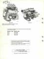
CI Fuel System
B27, B28E/F
260 1975-1983
book$4car$.com
4850 37th Avenue South
Seatjj^4flfly£y.SA^
109 423
B27 1976
B27E 1975
Note: new inlet manifold introduced in 1979 same type as fitted to B 27 F models.
The information included in this manual concernsthe CI fuel system fitted
to the following engines:
Engine Type
Model year
B27E
B28E
1975-1980
1981-1983
B27F
B28 F
1976-1979
1980-1982
Volvos are sold in versions adapted for different markets.
These adaptions depend on many factors including legal,
taxation and market requirements.
This manual may therefore show illustrations and text
which do not apply to cars in your country.
Order number: TP 30592/1
Supersedes TP 11122/3 (USA, Canada)
TP 11543/1 (Other markets)
We reserve the right to make alterations.
Group 23 Fuel
System
Contents
Contents
Operation
Page
2
12
Specifications
Special tools
Cl-System
Brief description
Location of components
Important information
Flushing system
Inspection of system
Faults detected
Adjusting line and rest pressures
Fault Tracing
Components, checking and replacement etc
Tank pump
Fuel pump + non-return (check) valve
Fuel accumulator
Fuel filter
Air-fuel control unit
Injectors
Control pressure regulator
Start injector, thermal time switch, impulse relay
Auxiliary air valve
Relays
Wiring diagram
A
B
B
B
C
1-18
1 -45
46-63
64
1-2
14
16
18
19
24
40
47
48
D
D
D
D
D
D
D
D
D
D
E
1-10
11-18
11 — 18
19-21
22-65
66-75
76-79
80-92
93-95
96-98
1-5
50
55
55
60
61
73
76
77
81
82
83
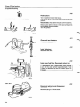
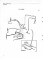
Constant Idle Speed System (cis-system)
Location of components
Idle speed
Fault symptoms
Basic setting and inspection of system
Faulttracing
Wiring diagram
F 1-14
G 1-11
H1
86
87
87
88
92
95
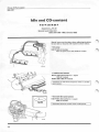
Idle speed & CO content,
checking/adjusting
General
B 27 E 1975-1978
1979-1980
B28E
B 27 F
B 28 F
J
J
J
J
J
J
1-2
3-7
8-15
8-15
16-30
16-30
96
97
98
98
100
100
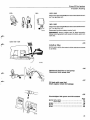
Air filter, air preheating
Fuel lines, replacing nipples
replacing lines
connections
Fuel tank 1975-1978, types
replacement
1978-1983
K 1-4
K5
K 6-14
K 15-19
K 20-22
K 23-43
K 44
Evaporative system
K 45-54
105
107
107
110
114
116
122
123
Miscellaneous
Index page 130
Group 23 Fuel
system
Specifications
Specifications
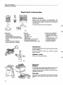
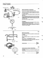
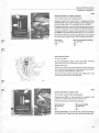
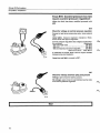
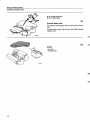
PLATES AND DECALS
Only those plates which contain information concerning the Cl-system are included in this section.
Model plate
Located on front right inner wing/fender.
Also includes type designation.
Note! Type of plate depends on model year. 1981 plate
shown adjacent.
<*^\
Vehicle identification number
USA and Canadian vehicles only. Visible from outside
of vehicle.
134 732
- 1979: left windscreen/windshield pillar
1980-: top of dashboard.
USA/Canada
-1980:
VC 2 6 4 65
1981-:
YV1 RX 6 9 4 X B 1 0 0 0 0 0 0
Vehicle identification
(type designation)
L1 000000
Note! Number coding varies with model year and
market. Numbers shown adjacent are only intended
as examples.
Ovriga
-1980:
2 6 5 61
1981-: YV1 2 6 4 68
k1 000000
1B 1 000000
"T~
T"
Engine type
J
136 604
Chassis number
Model year
designation
Engine type
61 = B 27 A
62 = B 28 A
64 = B 27 E
65 = B 27 F
68 = B 28 E
69 = B 28 F
Model year designation
B = 1975
A = 1980
E
H
L
M
B = 1981
C = 1982
D = 1983
= 1976
= 1977
= 1978
= 1979
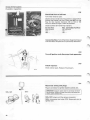
Engine serial number and part
number
Located on a plate in front of oil filter. B 28 E/F 1981-: a
decal on rear right end of cylinder head shows last
three digits of part number.
Exhaust emmissions plate
Fitted only to vehicles for Sweden, Australia, USA and
Canada.
uMr|wi»« an MMtnNrttu
TiUmtAt*
*t W(KM»«»»t^*
33ST"'" * wcn*xnw WK
5XJ»L" ^Z^ZZZ—**.
ox*
•iKtvr* KintwiMf
oSi^.^Tr'
VOLVO
Located on front left inner wing/fender.
Contains information on idle speed, valve clearance,
timing, CO-content etc.
Note!
„,„ „„,
- idle speed not stated on vehicles equipped with constant idle speed system (CIS)
- CO-content not stated on vehicles which have a
sealed CO-adjustment screw.
f,i*Qr-:.\
Group 23 Fuel
System
Specifications
CO-CONTENT & IDLE SPEED
General
• When checking/adjusting CO-content and idle speed on vehicles with automatic transmission always engage
neutral " N " and apply the parking brake
• CO-content should be checked/adjusted when engine is warm and idling
• If CO-content is not according to specifications ie. check values, it must be adjusted to setting value
• If CO is according to specifications it is not necessary to adjust the engine providing that it runs satisfactorily.
E-engines
Engine
type
Model year
Market
CO-content
setting value
(check value)
Idle Speed
r/s (r/min)
B27E
1975-1977
Sweden + Australia
Other markets
1.5
2.0
2.0
2.0
15.0 (900)
15.0 (900)
15.0 (900)
15.0(900)"
1978
1979-1980
B28E
(1.0-4.0)
(1.0-4.0)
(1.0-3.0)
(1.0-3.0)
2.0 (1.0-3.0) 2 '
2.0 (1.0-3.0) 2 '
2.0 (1.0-3.0)
15.0(900)"
15.0(900)"
15.0 (900)
CO-content
setting value
(check value)
Idle Speed
r/s (r/min)
1979
1.7(1.4-2.0)"
0.7 (0.4-1.0)"
1.0 (0.7-1.3)
1.7(1.4-2.0)"
1.0 (0.7-1.3)
1.0(0.7-1.3) 2)
1.0 (0.7-1.3) 2 '
15.0
15.8
15.0
15.0
15.0
15.0
15.0
1980
1981-1982
1.0(0.7-1.3)2>
1.0{0.7-1.3) 2,3 >
15.8 (950)
15.0{900)4>
1981
1982
1982-1983
Sweden + Australia
Other markets
Remarks
Automatic transmission 16.7 r/s (1000 r/min)
2)
Pulsair-system disconnected and plugged
11
F-engines
Engine
type
Model year
B27F
1976
1977
1978
B28F
Market
USA California
USA Federal
Canada + Japan
USA Federal + Canada
USA Calf. + Japan
(900)
(950)
(900)
(900)
(900)
(900)
(900)
Remarks
" Air pump must be disconnected and plugged
2)
Lambda-sond disconnected. When Lambda-sond is connected the CO-content must drop to less than 1.0%
31
Sealed CO-adjustment screw, excluding Japan + Canada 1981
*» CIS-system not fitted to USA Federal + Canada 1981
Group 23 Fuel system
Specifications
Cl-system
PRESSURES
Line pressure
Rest pressure, min
450-530 kPa (64-75 psi)
150-240 kPa (21-34 psi)
Control pressure, see below
CONTROL PRESSURE REGULATOR
Type of control pressure regulator fitted to vehicle
depends on engine type and model year. Identification
number is stamped in top of regulator (last three numbers).
0438 140
E-engines
Control
pressure
regulator
Bosch number . . . 005
Volvo number 269291-1
Engine
type
Model year
B27E
Early type
Late type Sweden + Australia
Other markets
. . . 018
269531-0
. . . 038
269837-0
X
X
X
X
B28E
/"^"N
F-engines
Bosch number . . . 004
Volvo number 463971-2
Control
pressure
regulator
Engine
type
Model year
B27F
1976
1977 USA
Other markets
1976-1977 special version USA
X
1978 USA California + Japan
Other markets
X
1979
B28F
1980-82
. . . 018
269531-0
. . . 021
1219952-7
. . . 029
269777-9
. . . 066
1269315-6
X
X
X
X
X
X
X
Groep 23 Fuel system
Specifications
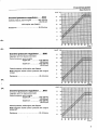
kp/cm 2 kPa
Control pressure regulator . . . 004
Control pressure, warm engine
345-375 kPa
(49-53 psi)
cold engine, see diagram
Resistance
20-30 ohms
1.5
150
1.0
100
0
32
kp/cm
10
50
20
68
30
86
40
104
50
122
10
50
20
68
30
86
40
104
50
122
60
140
70
158
80
°C
176
"F
132 943-2
kPa
Control pressure regulator . . . 005
(regulator with full load enrichment)
Control pressure, warm engine
engine off
engine on
3.0
300
275-305 kPa
(39-43 psi)
345-375 kPa
(49-53 psi)
Control pressure, cold engine, see diagram
Note! Diagram shows control pressure with engine
turned.
Resistance
20-24 ohms
0
32
kp/cm*
kPa
-r
,1
. 1
Control pressure regulator . . . 018
(regulator with full load enrichment)
Control pressure, warm engine
engine off
engine on
i
i
. !
1 !
• 4 II
i
- i4
l 11 I
1
'1
i
ii
r f ~ ~~ 1—i~
1
' '
. -(_L i
j_u-
1!
j i: 1
'•-j f\yi / /••
\ i
l ~ "1" ! i i
i 1 ! Ax,Ml 4
ISO T ^ "
- — n p - 7 ^ - ^ . - 0 - + - " i f l+^^-F
i
15
80
C
176 F°
132 943-6
i/f
,. 1 j
i / \ \ 1/ \
''
\ /i M -L
1 '
'
!/ ••;-/, I i
I N JC / \
Mi
T^ y i ;
M M
" " ' ' h i'
i'\ i{A\A"X t •
i i ; i
- - X\ J '- I ' M
i in J Jr \y
1 !
305-335 kPa
(43-48 psi)
345-375 kPa
(49-53 psi)
20-24 ohms
ir
J, J- - i il~i "1
f
-4-f-H
\-+—
x
•4fr
~
4
f
! --H4- :
M-JIII
1 ' 1
1
II
]
300
l
-,
iE~"Ai~zlli\r±
7\ f
i'
1
1
Resistance
_| i
1 i
I{
3.0
Control pressure, cold engine, see diagram
Note! Diagram shows control pressure with engine
turned off.
_ '
60
70
140 158
1
1
r
A\
AW/
/
J_VL''..:j/i
' .]/\
n\
0
32
/Ml
ill
.1
\V•
1
1 i
10
50
20.68
'
"
hII
i.j.!i l1.l
ill
,i
-- - •
r•1
30
86
j JJ_.jM
iI • • M r r r
!
- •
JJJ_
!
1 ~~I
1 1:::±::::::#
-tr
i i
±
40
50
104 122
60
140
70
158
1
80
*C
176 °F
132 943-3
Group 23 Fuel
system
Specifications
Control pressure regulator . . . 021
Altitude compensating device incorporated in regulator. Special versions for some B 27 F USA Federal 1976 and
1977.
Resistance
kp/cm
2
20-30 ohms
kPa.
kp/cm 2 kPa
±::::
J,
3,0
5.0
500 '
4.5
450
""-"3HEEEE
'
_-L_X-X
/ ^rFv~i~TT^
\\
| j i
::: ::::::::::::: /-;/fjf-fff"-
300
1
1/f „ j / ' 1 '
i
2,5
2,0
1
!
4.0
400^-!
.
35
JX
350 X
-1 „ I-4--T,
,!
X T
T
/
no
200
j* /
/
_ .J/ /, .
E ; _J_
'Ml
"
X M
j
i ;
TOO ——I—i—i—!— -
o.u
JUU
i
/ Jis-.
i v"f_
jA'\
"/
1
250
...:
,/ „ L L j
1
- J —T
. j
—L
-T
_J—
|
1,5
800
750
1067
1000
700
933
650
867
600
800
mm hg (Torr)
mbar
550
733
150
Control pressure, hot engine at different altitudes
1,0
100
10
50
20
68
30
86
40° C
The above graphs apply to air pressure at sea level and
up to altitudes of approx 600 m = 2 000 ft (947 mbar or
higher). For higher altitudes it is necessary to know the
prevailing air pressure to be able to calculate the correct
control pressure.
104° F
134 735
Control pressure, hot engine at different altitudes
Tolerance: ±25 kPa (0.25 kp/cm 2 = 3.6 psi).
Control pressure regulator . . . 0 2 9
(regulator with full load enrichment)
engine on
305-335
(43-48
345-375
(49-53
kPa
psi)
kPa
psi)
11
M
:
OCrt
30
3UU 4-
EJi
SCO
20
20
'-': ::
- _ -
^
::"".: pfr IJI ,M 1.
/ ^ /
....
A 1/1
. JlAL A\LCv/1
\J \ ' ;
.t . .
U3.*C
'
y nn
j _ ^c:T"i"4i
°
,/
/
\
II
"i
1 !
.
¥ / \\ : 1 t '
" J ^ l ^
:
, I
1
.; jJLil! liZzS
°° —~cy^r\y--r\\ -!•••-•
Control pressure cold engine, see dia.
Note! Diagram shows control pressure with engine
turned off.
Resistance
kPa
. i
T C
Note! B 27 F 1977 California: the full load enrichment
system is disconnected. Therefore specifications for
control pressure apply both with engine off and engine
running.
Control pressure warm engine
engine off
kp/cm2
20-24 ohms
Iff Jri\
O.J
jO
yr
- l / .
TTT 1 1" t 11 I
10 . :2 0 "! ; 30
40
0
32
50
68
86
104
T
50
122
60
140
I T
70
158
80
"C
176
°F
132 9 4 3 - 3
^
Group 23 Fuel
system
Specifications
Control pressure regulator . . . 038
kp/cm 2 kPa
(regulator with full load enrichment)
Control pressure, warm engine
engine off
305-335 kPa
(43-48 psi)
345-375 kPa
(49-53 psi)
engine on
Control pressure cold engine see diagram.
Note! Diagram shows control pressure with engine
turned off.
Resistance
20-24 ohms
0
32
10
50
20
68
30
86
40
104
50
122
60
140
70
158
80
176
°C
°F
132 943-5
Control pressure regulator . . . 066
Thermostat
valve
Intake
manifold
(regulator with cold engine acceleration enrichment)
hfrfrti
Note! B 28 F USA & Canada with pressure differential
switch: acceleration enrichment system is disconnected via control pressure regolator.
Thermostat closes at
Delay valve
delay time
colour
DIST
approx. 53°C (125°F)
Control pressure
hot engine
during acceleration (cold engine
but regulator warmed-up)
approx. 1 sec.
Grey
345-375 kPa
(49-53 psi)
145-175 kPa
(21-25 psi)
Delay valve
Control pressure regulator
kp/cm 2
kPa
1
1
J
!
PI
-
_M
1
1
1
~/. :-?5£
j rj jj?ly
1 1
I
A I
A;t::v
Jt : »B7
;
/
Am ipi L
1 1 i
111
J
I
J
I
_|
'
68
1 '
P
I
1
'
'
'
I '
'
IT
•
I I
j
1
'
1 1 1
'
|1 ! ]
\ l
I 1
i• 1
1
'>i 1
1
30
86
1
I
1
I
.
10 1 .20
SO
i l l
'
'
! 1
I
1
'
;
- ' 'S'/^
1 ( 11 1
j1
r' I
]
'
ffiW'n
1I
1
0
32
J1
1
1
1
jfi.i •• f 1 i
Mf
twi
lap- --.
fii 1
1
50
j
I
L.
1 / £• j
' \J ":;-: Ik '
L Ja" % 7
, jjjjjip -h
200
I 1
05
,:
J. •::• ••;:*
'
11
' [
I I
i
20
-TTT::
••-*:-/
1 t iT i
l i 1i 1 "J£•;•
.;1jT
i 11 1s.jS%g .:•. /1 • [ 1 T
11
1
.
i j (• ..j*' ri $p -. ^ >.. $-',£. % "1
-fefe Sp r
ppr
• ' • -1—|
Resistance below 12°C (54°F)
32-38 ohms
above 18°C (64°F). . . 16.5-19.5 ohms
j----
T
1 , ,
140
104
i
i
so
122
eo
140
70
158
'
80 1 1*C
176
*F
132 343-8
Group 23 Fuel
system
Specifications
START INJECTOR
Type of start injector fitted to vehicle depends on
model year and engine type. Identification number
(last 3 digits) is stamped on side of injector.
Injection time is controlled by the thermal time switch
(see graph below).
1981-1983: start injector is also controlled by an impulse relay so that engine receives additional fuel during warm starts. Impulse relay engages start injector
after approx. 1.5 sees, which is then followed by injectionforO.1 sees., pausefor0.3secs., injectionO.1 sees.,
pause 0.3 sees . . .
0 2 8 0 170 . -
* Impulse relay can also be fitted to B 27 E 1979-1980,
B 27 F 1978-1979 and B 28 F 1980. See page 78.
Start injector
. . . 400
. . . 404
269292-2
462865-7
165 cm 3 /min 115 cm 3 /min
Bosch number
Volvo number
Injected quantity
Engine
type
Model
year
B27E
1975-1978
1979-1980
B28 E
1981-1983
B27 F
1976-1979
B28F
1980-1982
X
X
X
X
X
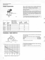
THERMAL TIME SWITCH
Type of thermal time switch fitted to vehicle depends
on engine type.
<fm
Temperature at which start injector is disengaged
B 27/28 E
35°C (95°F)
B 27 F
15°C (59°F)*
B 28 F
35°C (95°F)
-20°C 7,5 sec
Engagement time
35°C
Cut-out point
* Replacement part 35°C (95°F)
134 738
Cut-out point and engagement time at-20°C (-4°F) are
stamped on side of switch.
Sec
Tolerances: engagement time ± 2 sees. Cut-out point
± 4°C.
N
sN
x
V
>X
s. s
"***
V
1 '
20
-4
-10
14
0
32
1
k
—3
10
50
20
68
°C
°F
30
86
136 606
Engagement time at different temperatures
Group 23 Fuel
system
Specifications
INJECTORS
of
Type of injector fitted to vehicle depends on engine
type. Identification number is stamped on side of injector (three last numbers).
IT
0437502005*
K375Q23!
0437502013
Spare p a r t . . . 013 (1269274-5)
127 182
Injector, Bosch number
Volvo number
Opening pressure
no leakage permitted below
1975-1978
1979-1983
005*
269184-8
300-360 kPa
43-51 psi
240 kPa
34 psi
. . . 013
1269274-5
320-380 kPa
46-54 psi
260 kPa
37 psi
1975-1979
1980-1983
100 l/h
(0.8 I/30 sec.)
9.5 A
120 l/h
(1.0 I/30 sec.)
9.5 A
FUEL PUMP
Capacity at 500 kPa (71 psi),
12V and 20°C (68°F)
Current consumption max
TANK PUMP
Introduced in 1977 but may have been fitted to earlier vehicles.
Current consumption
1-2 A
Group 23 Fuel
system
Specifications
AUXILIARY AIR VALVE
Not fitted to vehicles with CIS-system
Type of auxiliary air valve fitted to vehicle depends on
model year and engine type. Identification number is
stamped on end of valve.
Valve fully open at
fully closed at
-30°C = -22°F
+17°C = +158°F
Valve is electrically controlled and should be fully
closed after 5 minutes engagement at an ambienttemperature of +20°C = 68°F.
0 280 140 . . .
134 740
Auxil ary air valv e
Engine
type
Model
year
B27E
1975
1976-1978
1979
1980
B28E
1981-1983
B27F
1976-1979
B28F
1980-1981
Bosch number . . . 200*
Volvo number 269309-1
Resistance
15-21 ft
. . . 202
269532-8
15-21 ft
. . . 114
. . . 213
. . . 110
. . . 100
1269193-7 1269319-8 1266910-7 460833-7
15-21 ft
40-60 ft
40-60 ft
40-60 ft
Man/Auto
Man/Auto
Man/Auto
Man
Auto
Man
Auto
Man/Auto
Man**
Auto**
* Spare part replacement. . . 202 (269532-8)
** Auxiliary air valve not fitted to vehicles with CIS-system.
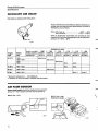
AIR FLOW SENSOR
/^E^fr^
Sensor plate height should be checked at max control
pressure = warm engine and fuel pump operating.
B27E 1975-1978
10
B27E 1979-1980
B28EB27FB28
\
Group 23 Fuel system
Specifications
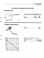
Constant idle speed system (CIS)
CONTROL UNIT
0 280 220..
Type of control unit fitted to vehicle depends on model
year. Identification number stamped on side of unit.
Bosch No
Volvo No
1981
1982
001
. . . 008
1274293-8 1274452-8
THERMAL TIME SWITCH
Bosch No
028
Volvo No
1306024-9
0280130...
136 608
ohoa
10000O
60000
Resistance at different temperatures see graph.
Suitable test temperatures
-10°C
32000-53000 fl
+20°C
8500-11500 n
+80°C
770- 1320 n
1
40000
30000
10000
8000
4000
3000
1000
800
-10
0
20
40
60
BO
100
•c
2ia »r
133 374
11
Group 23 CI system
Special tools
Special tools
999
Description - use
0976-4
0977-2
Flow differential gauge (USA and Canada): flow measurements used with 0977
Gauge (USA and Canada): setting the air-flow sensor plate. Used with 0976
2901-0
5011-5
5012-3
Clamping pliers
Pressure gauge: used with 5032 + 5116
Pliers: fitting hose nipples. 0 5 & 8 mm
5013-1
5014-9
5032-1
Pliers: fitting hose nipples. 0 1 0 mm
Flow metering unit: checking fuel flow and distribution
Nipple: connecting pressure gauge 5011
5102-2
5116-2
5151-9
Wrench: Adjusting CO content
Hose: connecting pressure gauge 5011
Adapter: CO meter (F engines)
5169-1
5170-9
5232-7
Spanner: removing/fitting fuel tank pump/gauge unit
Test relay: connecting fuel pump 1978Sealing tool: applying seal (steel ball) to the air-fuel control unit after CO adjustment
9934-4
Injector tester
Note: The 0 sign symbolizes diameter.
<
•• ^m&
j
>
12
Group 23 Fuel system
Special tools
5102
5116
oo L
Qi\
M
V
<&j£y.\
--^~~~~\
JL
5151
p
J
\\
5 1 7 0 ^ <%
S^TX15
B r ^
r#
^ ^
/w/R
/jSb
^ /
ITTTI
134 742
135 494
5151
5169
5232
9934
5170
13
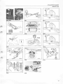
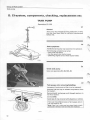
Group 23 Fuel system
Components
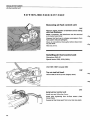
Cl-system
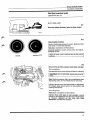
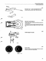
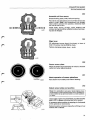
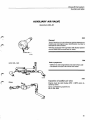
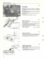
CI System components
For more detailed information refer to the design (construction) and function service manual
11 Injector
10 Start injector
9 Idle adjustment screw
8 Auxiliary air valve
/
12 Thermal time
switch
6 Fuel filter
7 Control pressure regulator
1 Air flow sensor
13 Air filter
5 Fuel accumulator
4 Fuel pump
3 Tank pump
14
121 949
Group 23 CI system
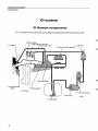
Function
The CI system is a mechanically operating fuel injection system with one injector per cylinder.
CI is short for "Continuous injection". The name is derived from the fact that the injectors
continuously spray fuel i.e. are open all the time the engine is operating. The amount of fuel
injected is therefore not controlled by variations of the injection time but instead by regulating
the supply of fuel to the injectors.
In principle the system operates by measuring continuously the amount of air flowing into the
engine, and adjusting accordingly the amount of fuel to be supplied. The air flow sensor (1)
measures the amount of incoming air, and the fuel is regulated by the fuel distributor (2).
1. Air-flow-sensor
7. Control pressure regulator
Continuously measures the amount of incoming air is an integral part of the fuel distributor.
Regulates control pressure.
2. Fuel distributor
Decreases control pressure during cold start and
warm-up resulting in a richer mixture.
It controls and distributes fuel to injectors. A pressure
regulator regulates both line and rest pressures.
There are different versions of regulators (which, for
example, give a richer mixture during accelerationcold engine), see specifications, page 4.
NOTE: A new type of pressure regulator was introduced in 1978. This new regulator blocks the fuel
return line when the engine is switched off.
8. Auxiliary air valve
3. Tank pump
A tank pump was introduced in 1977 to improve fuel
delivery- also installed on some earlier models.
It supplies fuel to the main fuel pump under constant
pressure and incorporates a non-return check valve
which minimizes the risk of vapour-lock.
Increases the quantity of air-fuel supplied to the
engine during cold start and warm-up (fast idle).
Note! Auxiliary air valve and idle adjustment screw not
fitted to engines with CIS-system. These engines have
instead an air control valve.
9. Idle adjustment screw
10. Start injector (previously called cold start injector)
4. Fuel pump
Main fuel supply to the system, incorporates a fuel
check valve to retain (rest) pressure into the system
when engine is shut down.
5. Fuel accumulator
Dampens fuel pump pulsations and maintains (rest)
pressure in the system after engine shuts down.
6. Fuel filter
Supplies extra fuel during cold engine starting. It is
controlled by a thermal time switch (12).
NOTE: On 1981-1983* models the start injector is
controlled by an impulse relay.
* Impulse relay may have been fitted to vehicles manufactured before 1981, see page 78.
11. Injectors
Atomizes injected fuel.
12. Thermal time switch
Senses coolant temperature and controls injection
time of start injector during cold starts.
15
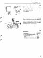
Group 23 CI system
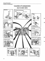
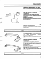
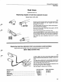
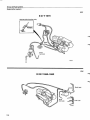
Location of components
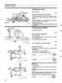
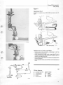
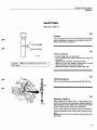
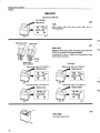
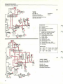
Location of components
B 27 E 1975-1978
Tank pump
Fuel pump, fuel accumulator
1978-
1975-1977
is
Relays
1975
1976-
Electronic relay
introduced in 1978
Fuel filter
Control pressure regulator
Air - fuel control unit
Thermal time switch
1976-1978^:
16
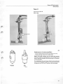
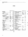
Group 23 CI system
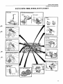
Location of components
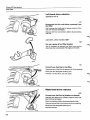
B 27 E 1979-1980; B 28 E; B 27 F; B 28 F
Tank pump
Fuel pump, fuel accumulator
1975-1977
Air- • fuel control unit
XI
c&y*
^SK^g^^
17
Group 23 CI system
Important
information
Important information
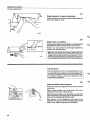
Before starting
Ensure that the vehicle is mechanically and
electrically sound before checking the CI system. Correct octane fuel supplied by well known companies
must be used.
The following points should be checked:
123 264
Mechanical
Electrical
Exhaust gas purification
-
-
- crankcase ventilation
- exhaust gas recirculation
(EGR)
- air pump/Pulsair system
- evaporative system
- Lambda-sond system
- catalytic converter
compression
valve clearance
vacuum hoses and connections
throttle control and kickdown cable
(auto)
- air filter
- intake manifold (air leakage)
- exhaust gas system (leakage)
spark plugs
HT leads
distributor cap
ignition coil
ignition setting, incl. advance
all electrical connections
constant idle speed system (CIS)
Cleanliness
Utmost cleanliness should be observed when working
on the CI system.
All fuel connections should be carefully cleaned
before removal.
Gaskets, seals
Always use new gaskets/seals.
136 611
Warning!
Battery
It is important when testing the different components
to ensure that the battery voltage is not too low.
A battery charger can be connected if necessary. Max.
charging current 15 A.
Fire risk
Extreme care should be taken to avoid causing sparks
especially when testing the start injector and injectors.
134 731
18
Group 23 CI system
Flushing
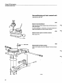
A. Flushing fuel system
Fuel tank should be flushed if water has (or is believed
to have) .condensed in fuel system.
Presence of water in fuel system is indicated by
-
engine stoppage
difficult cold starting
erratic idling
low output (poor performance).
The following equipment is necessary to flush fuel
system:
- fuel tank drainer or a large container for collecting
fuel
- approx. 6 litres (6 US qts) white spirit (Shell Minera
Spirits 135, Shell K30, Esso-Versol or equivalent)
- two drain pans approx. 1.5 litres (1.5 US qts) each
- two hoses approx. 1 metre (3 ft) long, to fit to the
return line and the fuel pump
- clamping pliers 2901
- t e s t relay 5170(1978-).
A1
Clean fuel tank
Drain fuel and fill tank with approx. 4 litres (4 US qts) of
white spirit.
Rock car so that white spirit mixes with any water
present in tank.
Drain tank and refill with clean petrol (gasoline).
A2
Fit a new tank p u mp filter
If necessary see page 50.
A3
Disconnect tank p u m p
Disconnect plug in boot (trunk).
19
Group 23 Fuel
Cl-system,
system
flushing
A4
Connect fuel pump to a vessel containing white
spirit
(at least 2 litres = 2 US qts)
Block fuel line between pump and tank. Use clamping
pliers 2901.
Disconnect line from pump inlet.
Connect one end of hose (approx. 1 m = 3 ft) to pump
and submerge other end in a jar containing white
spirit.
A5
Connect return line to an empty vessel
Separate return line on firewall. Connect one end of a
hose (approx. 1 m = 3 ft) to return line and submerge
other end in an empty vessel (capacity approx. 1.5
litres = 1.5 qts).
A6
Install new fuel filter
If necessary see page 60.
A7
Remove injectors
Place ends of fuel lines in empty vessel (capacity approx. 1.5 litres = 1.5 US qts).
20
Group 23 Fuel system
Cl-system, flushing
B 27 E 1975-1978
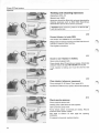
A8
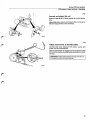
Remove air filter
B 27 E1975-1978: Also detach hose from air filter and
rubber bellows.
1975-1977
A9
Prepare start of fuel pump
7975-7977
Withdraw plug from air flow sensor.
134 753
1978-1980
1978-1980
Connect test relay 5170.
134 742
1981-1983
7987-7983
Connect test relay 5170.
Withdraw plug from ignition system control unit.
E
]
[
Take care not to lose rubber seal in connector.
&=
134 754
21
Group 23 Fuel system
Cl-system, flushing
A10
B 27 E1975-1978
Other models
u.
Flush system
Turn on ignition to start fuel pump.
B 27 E1975-1978: Lift air-flow sensor plate to topmost
position.
Other models: Push down the plate until it bottoms.
Release plate after 1.5 litres (1.5 US qts) white spirits
have flushed through system.
Turn off ignition.
\
All
Clean and test injectors
If necessary see page 74.
A12
Install injectors
Reconnect fuel lines.
135 431
A13
Install new fuel filter. Reconnect return line
It is necessary to fit a second new filter because
some of the water which has condensed in fuel
system is absorbed by the filter when system is
flushed.
134 757
1975-1977
A14
Reconnect wiring to air-flow sensor
1975-1977 models
Reconnect plug to air flow sensor.
22
Group 23 Fuel system
Cl-system, flushing
1978-
1978-1980
1981-
Disconnect test relay 5170 and reconnect lead to terminal 1 on ignition coil.
7987-7983
Disconnect test relay 5170 and reconnect lead to terminal 1 on ignition coil.
Reconnect ignition system control unit.
IMPORTANT! Ensure rubber seal is fitted correctly.
Water entering system will cause corrosion, poor contacts etc.
B27E 1975-1978
A15
Install air filter
B 27 E1975-1978: also attach rubber belows and hose
to air filter.
120 402
\
. /
A16
Reconnect fuel line to fuel pump
Reconnect tank pump lead
A17
Fill tank with new fuel
Start engine. Check for leakage
A18
Check/adjust idle speed and CO-content
B 27 E 1975-1978
1979-1980
B 28 E
B 27 F
B 28 F
Page
97
98
98
100
100
23
Group 23 Fuel
Cl-system,
system
inspection
B. Inspection of Cl-system
Special tools: 2901,5011,5014,
5116, 5170 (1978-)
(alt 0976+0977
for USA & Canada), 5032,
Engine must be cold (below +30°C = 86°F) at start of inspection as it is
necessary to check control pressure, auxiliary air valve and start injector in
a cold state.
Note! B 27 F: temperature must be (below 15°C = 60°F) to be able to check
thermal time switch in car.
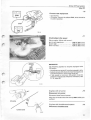
B 27 E1975-1978
Other models
Preparatory w o r k
Operations
B1-3
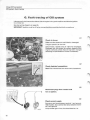
B1
Remove air filter
B2
Disconnect plug from ignition system control
unit
Safety precaution: This is also necessary on some
models to enable fuel pump to be started.
B3
Disconnect connectors f r o m :
- control pressure regulator
- auxiliary air valve (not fitted on vehicles with CIS)
These components must be disconnected or they will
heat up during inspection and results will be invalid.
(It can take as long as an hour for a component to cool
down again.)
24
Group 23 Fuel
Cl-system,
system
inspection
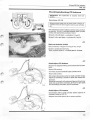
Inlet system
B 27 E1975-1978
Operation
B4
B4
Check that inlet system does not leak
Air must not leak between air-flow sensor and engine.
Repair as required.
Check:
- B 27 E 1975-1978: rubber bellows between air-flow
sensor and intake manifold.
- hose connections at auxiliary air valve (air control
valve) and start injector
- all vacuum hoses
- O-rings
- if all screw joints are tight
- that injectors are fitted correctly and that rubber
seals are intact.
Start injector
Impulse relay
Operations
B5-10
B5
Remove injector
Allen key 5 mm.
B6
Check start injector and t h e r m a l t i m e switch
IMPORTANT! Withdraw connector from impulse relay
during following check.
136 616
Hold injector above a suitable container.
Sec
Run starter motor and observe injector.
—"s-**sT
,
>
_,
Sr
^^
A
S_
%
v
]
Fuel should be injected continuously when starter
motor is cranked. Engagement time does however
depend on engine temperature, see graph adjacent.
—r
p-
Note! Some B 27 F engines may have been fitted with a
thermal time switch with a 15°C (59°F) cut-out point.
—+:-:-::±t::::
IT
-20
-4
-10
14
I .
1
1—
0
32
Incorrect injection time: remove connector from start
injector. If injection is interrupted then thermal time
switch is defective. If injection is still not interrupted,
start injector is defective.
\l
r~"'
10 .5_.
50
20
68
30
86
°C
°F
Incorrect injection time: test with a new thermal time
switch.
Injection time at different temperatures
Tolerances: injection time ±2 sees. Cut-out temperature
±4°C (8°F)
No injection
\B46.
25
Group 23 Fuel system
Cl-system, inspection
Engines with impulse relay
B7
Check impulse relay
Connect plug to relay.
Hold start injector above a suitable container.
Run starter motor and observe injectors.
Fuel should be injected after approx. 1.5 sees, with
subsequent injection for 0.1 sees. - pause 0.3 sees. injection 0.1 sees. - pause 0.3 sees . . .
136 617
Incorrect timing: test with a new impulse relay.
No injection: defective relay or wiring.
1975-1977
B8
Start fuel pump
Place hand on fuel filter to check that pump is operating (filter vibrates slightly).
1975-1977: Withdraw connector from air-flow sensor.
1978-: Connect test relay 5170.
Turn on ignition to start fuel pump.
1978-
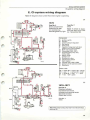
Fuel pump does not start: Check fuses, wires and
relay. See Wiring diagrams on pages 83-85.
****T'$V
134 768
B9
Make sure that start injector does not leak
Max. rate = 1 drop per minute.
If greater, replace injector.
B10
123 304
26
Turn off ignition
Install injector
Group 23 Fuel
Cl-system,
system
inspection
Air-fuel control unit
Operations
B 27 E
B11-13
1975-1978
B11
Remove rubber bellows f r o m air-flow sensor
B12
Check plate position
No part of plate may touch air venturi. Make sure that
plate does not have any side play.
J^*\
Side play: recondition air-flow sensor.
Incorrect position: loosen centre screw and adjust.
Retighten screw.
Correct
Incorrect 108604
Height of sensor plate is checked later at max control
pressure.
B13
Ensure t h a t air-flow sensor plate does not j a m
Turn on ignition.
Depress plate for a short while and listen to injectors.
IMPORTANT! B 27 E 1975-1978: sensor plate must be
lifted.
Note! Control pressure offers some resistance when
depressing plate, do not mistake this for jamming.
Injectors should only buzz when plate is depressed.
On release, plate should return to rest position and
buzzing should stop.
Turn off ignition.
Plate jams: recondition air-flow sensor.
Injectors buzz with plate in rest position: control
plunger in fuel distributor has jammed, clean/replace
as required. Injectors do not buzz with plate
depressed: incorrect line pressure.
27
Group 23 Fuel
Cl-system,
system
inspection
Auxiliary air valve
Operation
B14
B14
Check that auxiliary air valve opens
Valve should be partly open at room temperature and:
Fully open at -30°C (-22T) fully closed at +70°C
(158°F).
Use a penlight to illuminate valve when checking
operation. Replace valve if defective.
Connect plug to valve.
Closing operation of auxiliary air valve is checked at a
later stage.
Checking all pressures
Operations
B15-24
875
Connect pressure gauge 5011
Turn off ignition.
Connect gauge between control pressure regulator
and fuel distributor.
Use hose 5116 and nipple 5032.
B16
Turn on ignition to start fuel p u mp
B17
Check line pressure
Turn gauge cock on 5011 to position 1 (ie. towards fuel
distributor).
Record pressure when it is stable.
Line pressure = 450-530 kPa (64-75 psi).
Too low
-IB4^
Too high
B53
B18
Check control pressure (cold control pressure
regulator)
Turn off engine.
Turn gauge cock on 5011 to position 2 (at right angles
to hoses).
Control pressure regulator should be at room temperature.
Correct control pressures at different temperatures
are shown in graphs on pages 29 and 30.
Too low: test with a new control pressure regulator.
Too high
28
B55
Group 23 CI system
Cl-system,
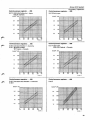
Control pressure regulator... 005
Control pressure regulator. . . 004
B 27 F1978 USA California + Japan
1979 All markets
kp/cm2
2.5
B 27 E Early type
kp/cm2
kPa
kPa
— -^
250
Ail
-A~~2-
__ __
2.0
4 - - ? ?
200
:: :: _z
1.5
150
1.0
100
_:
„?__2-_:
^ " 2
S~ 7'
zz.Z7
Z~2
z
z?
0
32
20
68
10
50
30
86
40
104
°C
°F
0
32
10
50
30
86
20
68
132 342 - 2
Control pressure regulator. . . 018
Control pressure regulator.. . 029
B 27 E Late type Sweden + Australia
B 27 F1976 All markets
1977 Japan + Canada
B 27 F 1977 USA
1978 USA Federal + Canada
kp/cm2
kp/cm2
kPa
2.0
200
1.5
1.0
0.5
_
_
150
100
"
A
^t-Z
*Z-S
S---*
<ttZZ2.
-_<_-.,*
, 2 _„ ?
JL -S
//
_tt.^dZ
2ZZZ7
- /zy
2
50
0
32
10
50
2.0
1.5
J_
0.5
__
30
86
«d
/
>
!
_
150
J/
£
100
j? .
. j?
.^
?
y
_i
I
0
32
10
50
20
68
30
86
B28F
kp/cm 2
kPa
kPa
—:-::-:
I
3.0
J
0
32
10
50
20
68
_ -
7 $ ••"•: V
ZMW
J- £ § 3
- -
£"£<'
2.5
_ _
250
7--1/ 5a s ^
2.0
Zv s-:. ;;• 7
200
~~
_-
———— —
30
86
_ ~zi
4ii-
/ :i|: ittj jfi
^ ii; it ^
— S S
50
:
40
104
*. •:"•; i-i f
300
x
^--Z7
±
i | 1 gj *
;
„2_rzf
0 •>
J
£
Control pressure regulator. . . 066
, 2 - :_ :^^ : "
^
/
^ •"• -*
r ^
B 27 E Late types excl Sweden + Australia
B28E
j,-
^
^
50
40
104
^~
+z?z
Z7
_l
2 /• tk
.?*
>
±
20
68
~ ~> s
200
__
1.0
40
°C
104
°F
132 942-6
kPa
Control pressure regulator. . . 038
kp/cm2
inspection
40
°C
104
°F
132 942-3
1.5
150
0
32
^ %%%%
^-2
:
*;??r
7,
-
^S
— 2iz _ : :
10
50
20
68
::
Z"~-~~~
: :__
z "_~ ~ _ __ _
30
86
40
104
°l
132 942-7
29
Group 23 Fuel
Cl-system,
kp/cm2
system
inspection
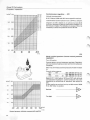
Control pressure regulator . . . 021
kPa
Altitude compensated.
B 27 F Federal 1976 and 1977 some special versions.
Tolerances for control pressure are ±25 kPa (± 3.6 psi).
3,0
300
2,5
250
2,0
200
1,5
150
1,0
100
Diagram on left is based on air pressure at sea level
and up to altitudes of approx. 600 meters (2000 ft) i.e.
947 mbars or higher. For altitudes in excess of this it is
necessary to know air pressure at time of test.
B19
Check control pressure (warm control pressure
regulator)
Turn off engine.
Connect plug to control pressure regulator. Regulator
will now receive heating current and control pressure
increases.
After max. 5 minutes control pressure should increase
to:
Control valve pressure
. . . 004 + . . . 066
345-375 kPa (49-53 psi)
. . . 005
275-305 kPa (39-43 psi)
. . . 018 + . . . 029+ . . . 38 .. 305-335 kPa (43-48 psi)
kp/cm2
kPa
—
5.0
500
4.5
450
3.5
3.0
400
i^i^
:::::: :::=::+:::::il::S:
/•
H
y
4.0
+—HT
-
!/
£
y(/
.- - -y/.
".• j" ' t
350
/
J
y
/
/\
/
vs
Jr
/
Y
J
700
933
i
ii
650
867
600
800
550
733
mm hg (Torr)
mbar
Control pressure, altitude compensated regulator
30
B56
Too high
B55
! •
...
750
1000
Too low
y
300
800
1067
Note! B 27 F USA Federal 1976 and 1977 with altitude
compensated regulators: control pressure may vary
depending on prevailing air pressure, see graph on
left.
Graph applies at sea level and up to 600 meters (2000
ft) ie. 947 mbar or greater.
Group
23 Fuel
Cl-system,
B27E,
B28E
B27 F 1976 all
types
1977 not
California
1978 USA Federal +
B27 F 1977 California
system
inspection
Canada
IMPORTANT! B 27 F 1977 California: full load enrichment system is not connected.
r
Plug
136 619
B20
Check e n r i c h m e n t at full load
Check v a c u u m hose f o r leaks a n d m a k e sure t h a t it is
correctly c o n n e c t e d .
Evacuate hose c o n n e c t e d t o c o n t r o l pressure regulator. C o n t r o l pressure s h o u l d increase.
IMPORTANT! System must be evacuated carefully or
regulator may be damaged.
At a d e p r e s s i o n ( v a c u u m ) of 50 kPa (7 psi) c o n t r o l
pressure s h o u l d be 3 4 5 - 3 7 5 kPa ( 4 9 - 5 3 psi).
C o n t r o l pressure s h o u l d r e t u r n t o the initial valve
w h e n p u m p is r e m o v e d .
Reconnect v a c u u m hose.
Note! This test can also be performed with engine running by comparing the gauge values with the vacuum
hose connected and then disconnected.
Thermostat valve
B28F
Operation B 21 on next page applies only for engines
w i t h o u t a pressure differential switch. On engines with
a pressure differential switch the acceleration enrichment system via the control pressure regulator must
always be disconneted.
Plug
Pressure differential
switch
Control
pressure regulator
31
Group 23 Fuel
Cl-system,
system
inspection
Thermostat valve
B21
Check acceleration enrichment
B 28 F without pressure differential switch.
Check vacuum hoses for leaks and correct connection.
Disconnect hose from intake manifold and connect it
to a vacuum pump.
Evacuate system until pressure drops to approx. 50
kPa (7 psi).
Disconnect pump quickly and record control pressure
on gauge 5011. Control pressure should drop to 145175 kPa (21-25 psi) for one second and then return to
the initial valve.
Reconnect hose to intake manifold.
If incorrect:
Check that delay valve is connected correctly, see fig.,
and that thermostat valve is open.
Thermostat valve should be open at temperatures
below 55°C (131°F). (Closing operation of valve is
checked at a later stage.)
2
131 608
B22
Check rest pressure
Turn gauge cock on 5011 to position 2 (at right angles
to hoses).
Turn off ignition.
Record pressure when it is stable and for a further
minute.
Rest pressure = 150-240 kPa (21-34 psi).
Pressure does not drop but is incorrect: adjust line
and rest pressures, see page 47.
Pressure drops
B58
B23
Check pressure drop for 20 minutes
Especially important if hot starting problems are encountered.
Pressure after 20 minutes should be at 150 kPa (21 psi).
Too low
120 393
32
B58
Group 23 Fuel system
Cl-system, inspection
B24
Disconnect pressure gauge 5011 and nipples
(hose)
Turn off engine.
Reconnect hose from control pressure regulator to
fuel distributor.
120 399
Air-flow sensor
Operation B25
B25
Check air-flow sensor plate rest position
Fuel pump must be operating for this test and control pressure at max. value.
B 27 E1975-1978
B 27 E 1975-1978
Turn on ignition.
Upper edge of plate should lie flush or at most 0.3 mm
(0.012 in) below cylindrical part of air venturi, see fig.
Turn off ignition.
Incorrect position: adjust by bending/straightening
spring beneath plate.
Other models
Other models
Turn on ignition.
Upper edge of plate should lie flush or at most 0.3
mm (0.012 in) above cylindrical part of air centuri,
see fig.
Turn off ignition.
Incorrect position: adjust by tapping pin upwards/
downwards. It is necessary to remove upper part of
air-flow sensor to obtain access to pin.
33
Group 23 Fuel system
Cl-system, inspection
Auxiliary air valve
Operation B26
B26
Check that auxiliary air-valve closes
Turn on ignition.
Valve should be completely closed after approx. 5
minutes at 20°C (68°F).
Turn off ignition.
Does not close: tap lightly on valve. If it closes now it is
not defective (engine vibrations usually cause valve to
close).
If valve still does not close
Injectors
Fuel distributor
Operations B27-40
B27
Remove injectors from cylinder heads
B28
Make sure that fuel distributor does not leak
internally
Turn on ignition to start fuel pump.
Observe injectors, they may become moist but
must not start to drip.
Turn off ignition.
Injectors drip: internal leakage in fuel distributor.
Replace.
B29
Check injectors for leakage at rest pressure
Depress* sensor plate until slits in control plunger
are open and observe injectors.
B 27 E 1975-1978: sensor plate must be lifted.
Injectors may become moist but must not drip in a
15 second period.
One or more injectors leak: clean injectors and
test with test apparatus described on page 74.
34
Group 23 Fuel
Cl-system,
system
inspection
B30
Check difference b e t w e en fuel delivered from
each injector
This test should only be carried out in cases of obvious
engine malfunction. Otherwise continue with operation B40 on page 38.
There are two types of measuring equipment in use:
- meter 0976 (USA + Canada), see operation B34 on
page 36.
- fuel metering unit 5014, see operation B31 below.
Fuel metering unit 5014
Operations
B31-33
B31
Connect fuel metering unit 5014
To obtain correct readings all hoses should be either
empty or full at start of test.
B32
Check fuel deviation
Turn on ignition to start fuel pump.
Depress* sensor plate halfway. Keep it depressed in
this position until 100 cm 3 of fuel is collected in one of
measuring cylinders. Then release plate.
B 27 E 1975-1978 sensor plate must be lifted.
Injectors should start delivering fuel at same time.
Max fuel deviation must not exceed 20%.
Turn off ignition.
Greater than 20%: repeat test to be exactly sure.
If deviation is still greater than 20%, swap hoses between two injectors (one correct and one faulty) and
repeat test.
If results are still same, injector or hose is defective.
Clean injector and test in test equipment described on
page 74.
If other injector malfunctions, fuel distributor is defective and will have to be replaced.
35
Group 23 Fuel
Cl-system,
system
inspection
B33
Disconnect fuel metering unit
Pour fuel back into tank.
B40>
Proceed to
Test meter
Operations
0976
B34-40
USA and Canada only
Note! Fuel pump must be running during test. A battery
charger (max. charge 15A) can be connected to prevent
battery from discharging.
Low battery voltage will decrease fuel pump capacity
and test results will be invalid.
B34
Connect meter 0976
Support meter on a flat surface, next to car, and make
sure that it is horizontal by checking built-in spirit
(bubble) level.
Connect injectors to hoses from meter, injector No. 1
to hose No. 1 etc.
Insert meter return line in fuel tank.
B35
Evacuate meter and lines
Turn on ignition.
Depress air-flow sensor plate to its max. position. Insert tool 0977 so that plate does not move.
Depress meter switches one at a time, and open meter
knob. Continue until both tubes in meter are evacuated and free from air bubbles.
Remove 0977 and release air-flow sensor plate.
36
Group 23 Fuel system
Cl-system,
inspection
B36
Check fuel flow at idle position
Turn meter knob to left (white spot).
Depress switch for injector No. 1. Depress air-flow
sensor plate until a flow of approx. 6 cm 3 /min is obtained. Keep plate in this position with tool 0977.
Depress switches for remaining injectors one at a time
in ordertofind out which injector has lowest fuel flow.
Depress switch for injector with lowest flow. Position
tool 0977 so that flow becomes 6.0,6.6 or 7.2 cm 3 /min.
Check fuel flow for remaining injectors. Flow values
for remaining injectors can only lie above set value.
Set
6.0
6.6
7.2
value
cm 3 /min
"
"
Max permissible fuel flow
7.2 cm 3 /min
7.9 "
8.6 "
Incorrect fuel flow:
Turn off ignition.
At fuel distributor, swap a fuel line (with incorrect
flow) with a fuel line having a correct flow.
Repeat flow test.
If fault still remains on same injector, either the injector or fuel line is defective. Clean injector and test in
test apparatus described on page 74.
If fault moves to other injector, fuel distributor is defective and will have to be replaced.
-of
B37
J
'MM
Check fuel flow at part load
Turn meter knob to right (white spot).
Position tool 0977 so that fuel flow for injector with
lowest flow becomes 40, 50 or 60 cm 3 /min.
'fC-
Check fuel flow for remaining injectors.
£ ^•—
8^
-^
'•
M :
/' .
&
>
%
Set fuel flow
40 cm 3 /min
50 "
60 "
Max permissible
46 cm 3 /min
57 "
68 "
Incorrect fuel flow: Turn off ignition. Swap fuel lines'at
fuel distributor. Repeat test as previously described.
135 139
37
Group 23 Fuel
Cl-system,
system
inspection
B38
Check fuel flow at full load
Turn meter knob to right.
Depress sensor plate to its max position. Check which
injector has lowest fuel flow. Place tool 0977 so that
flow for this injector becomes 120 or 140 or 160
cm 3 /min. Select as high a value as possible.
Check fuel flow for remaining injectors.
Set fuel flow
120 cm 3 /min
140 "
160 "
Max. permissible fuel flow
131 cm 3 /min
153 "
175 "
Incorrect fuel flow: Turn off ignition. Swapfuel lines at
fuel distributor. Repeat test as previously described.
B39
Turn off ignition and disconnect test apparatus
B40
Install injectors
Check rubber seals. Replace if hard/worn.
~
I
B41
F
Reconnect wiring and plugs
Plug in connector to ignition system control unit.
1975-1977
1978-
IMPORTANT! Ensure rubber seal in connector is installed correctly. Without it water can enter and cause corrosion, poor contacts etc.
1975-1977: plug in air-flow sensor connector.
1978-: disconnect test relay 5170. Reconnect wire to
ignition coil.
38
Group 23 Fuel system
Cl-system, inspection
B42
Check/adjust throttle cable
Throttle pulley should strike stop at idle position. Cable should be taut but should not move pulley. Adjust
using cable sleeve.
At full throttle, pulley should strike other stop.
B43
Check/adjust kick-down cable (auto)
Depress accelerator to floor.
IMPORTANT! Do not adjust throttle by hand otherwise
setting will be incorrect.
At full throttle distance from cable sleeve to clip
should be 50.4-52.6 mm (1.98-2.07 in).
Adjust using cable sleeve.
B 27 E 1975-1978
B44
Install air filter
B 27 E1975-1978: also attach rubber bellows and hose
to air filter.
B45
Check/adjust idle and CO-content
B 27 E 1975-1978
1979-1980
B 28 E
B 27 F
B 28 F
Page
97
98
98
100
100
131 621
End of inspection
39
Group 23 Fuel
Cl-system,
system
inspection
Different faults discovered during inspection
Operations
B46-63
From B6: No fuel injected from start
injector
When fault has been rectified
proceed
from B7
B46
Check for voltage at start injector w h e n starter
motor is operating
Measure voltage across both pins.
Voltage: test using a new start injector.
120 374
B47
Check for voltage between plug and ground
when starter motor is operating
Voltage: indicates a defective thermal time switch or
an open circuit in the lead between it and the start
injector.
No voltage: open circuit in lead between starter motor
and start injector.
123 273
End
40
Group 23 Fuel system
Cl-system, inspection
From B17: Line pressure too low
When the fault has been rectified proceed from
818
B48
Fuel leakage?
Check for fuel leakage between fuel pump and fuel
distributor.
Cars equipped with a fuel leakage return line between
fuel accumulator and fuel tank: remove tank cap to
release overpressure from fuel system and disconnect
hose from fuel accumulator. Check thatfuel accumulator does not leak. Reconnect hose.
B49
Check tank pump
Tank pump was introduced in 1977 but may have been
fitted to some models before this.
Unscrew fuel tank cap and listen for sound of pump.
A defective tank pump often causes a noisy main fuel
pump.
Tank pump does not work: check fuse in boot/trunk
(1975-1978) or fuse No. 5 in fusebox (1979^).
134 787
B50
Check tank pump current consumption
Connect an ammeter as illustrated.
Current should be 1-2A.
Incorrect: Check tank pump and filter for blockages. If
correct, retest with a new tank pump.
No current: Check for voltage at pump. If correct test
with a new pump.
113 631
41
Group 23 Fuel
Cl-system,
system
inspection
B51
Check fuel pump capacity
Turn off ignition.
Unscrew fuel tank cap to release overpressure from
fuel system.
Disconnect return line at connection in engine compartment and hold end above a measuring cylinder.
Turn on ignition for 30 seconds.
Min. volume of fuel should be:
1975-1979
1980-
0.8 litres (0.75 US qts)
1.0 litres (1.0 US qts)
Reconnect return line.
Incorrect pump capacity: Retest with a new fuel
pump. If this does not help, fault may be due to a
blocked fuel filter, fuel line or fuel distributor.
B52
Adjust line and rest pressures
See page 47. Clean line pressure regulator and check/
replace O-rings.
End
42
Group 23 Fuel system
Cl-system, inspection
From B17: Line pressure too high
When the fault has been rectified proceed with B18
B53
Check that return line is not blocked
Turn off ignition.
Unscrew fuel tank cap to release overpressure.
Disconnect return line from fuel distributor and blow
through line.
Blocked line: clean/replace.
OK: check that fuel fitting screw holes are not blocked.
Reconnect return line.
B54
Adjust line and rest pressures
See page 47. Check line pressure regulator and check/
replace O-rings.
End
From B18 and B19: Control pressure
too
high
(cold/warm
control
pressure regulator)
When the fault has been rectified proceed with B19
(B20)
B55
Check that return line is not blocked
Turn off ignition.
Unscrew fuel tank cap to release overpressure.
Disconnect return line from control pressure regulator. 1978-: also disconnect line from fuel distributor.
Blow through line.
Blocked line: clean/replace.
OK: check that fuel fitting screw holes are not blocked.
Retest with a new control pressure regulator.
Note! 1978-: fault may be due to a blocked line
pressure regulator.
134 788
End
43
Group 23 Fuel system
Cl-system, inspection
From B19: Control pressure too low
(warm control pressure regulator)
When the fault has been rectified proceed with
B20
B56
Check for voltage at control pressure regulator
Connect a test lamp across plug pins. Lamp should
light.
Lamp lights: measure regulator resistance. Resistance varies with type of regulator.
Control pressure regulator (last 3 digits of identification number)
Resistance
005+018+029+038
20-24 ft
004+021
20-30 ft
066 at temperatures below 12°C 54°F
32-38 ft
above 18°C (64°F) . 16.5-19.5 ft
If resistance is correct, fault is due to a poor contact
between plug and regulator.
132 777
Lamp does not light: proceed to B57.
B57
Check for voltage between plug and ground
Voltage: open circuit in lead to ground.
No voltage: open circuit in lead between pump relay
and control pressure regulator.
132 778
End
44
Group 23 Fuel system
Cl-system, inspection
From B22 and B23: Rest pressure
drops
When the fault has been rectified proceed with
B23 (B24)
B58
Check rest pressure. Gauge cock in position 1
Turn on ignition to build up pressure in fuel system.
Turn off ignition.
Turn gauge cock on 5011 to position 1 (towards fuel
distributor).
/0*\
1975-1977
Wait and record pressure after 5 minutes, (this is
necessary because fuel accumulator compensates for
any leakage as long as it contains fuel under pressure).
Pressure does not drop in position 1: fault is due to one
or more of the following:
- fuel line leak
-1975-1977: fuel flow through control pressure
regulator too great. Test with a new regulator.
- 1978-: needle valve in line pressure regulator does
not close. Clean/replace needle valve and fitting.
B59
Fuel leakage? Check for fuel leakage between
fuel pump and fuel distributor
Cars equipped with a fuel leakage return line between
fuel accumulator and fuel tank: remove tank cap to
release overpressure from fuel system and disconnect
hose from fuel accumulator. Check thatfuel accumulator does not leak.
Reconnect hose.
B60
Make sure that line pressure regulator does not
leak
Unscrew fuel tank cap to release overpressure.
Switch on ignition to build up pressure in fuel system.
Switch off ignition.
Disconnect return line (junction nextto filter) and hold
end of hose up. If fuel flows out of hose, line pressure
regulator is leaking.
123 291
Reconnect return line.
Line pressure regulator leaking: Replace O-ring. If this
does not help, replace fuel distributor.
45
Group 23 Fuel system
Cl-system, inspection
B61
Check fuel pump non-return valve
Switch on ignition to build up pressure in fuel system.
Switch off ignition.
Block line between tank pump and fuel pump using
pliers 2901.
Record rest pressure for 5 minutes.
Rest pressure drops: start injector or line to it, leaking.
Rest pressure does not drop: non-return valve is leaking, replace.
End
From B26: Auxiliary air valve does
not close
When the fault has been rectified proceed with
B27
B62
Check for voltage at auxiliary air valve
Connect a test lamp across pins. Lamp should light.
Lamp does not light: check ground connections. Connect lamp across yellow wire (1975) or blue wire
(1976-) and ground.
B63
Check auxiliary air valve resistance
Connect an ohmmeter across auxiliary air valve plug.
Model year
1975-1979
1980-1983
Correct: indicates poor plug contact.
Incorrect: replace auxiliary air valve.
End
46
Resistance
15-21 ft
40-6011
Group 23 Fuel system
Cl-system, adjusting pressures
Adjusting line and rest pressures
B64
Add or remove shims from line pressure regulator as
required.
1975-1977
Line and rest pressures are effected to a similar extent
by shims. Both increase by addition of shims and viceversa.
Shims are available in following thicknesses:
1978-
1975-1977
1978-
Line pressure
Rest pressure
132 691
Thickness
0.1 mm
0.5 mm
Pressure change
6 kPa (0.85 psi)
30 kPa (4.3 psi)
0.1 mm
0.15 mm
0.6 mm
15 kPa (2.13 psi)
22 kPa (3.2 psi)
90kPa(13psi)
450-530 kPa
(64-75 psi)
150-240 kPa
(21-34 psi)
47
Group 23 CI system
Cl-system, Fault tracing
C. Fault tracing, CI system
(V...!.'.U.!<-1
lOeU.jiM.''
iHMIWIintlllM W
*f I I
1
»
II I MlMilllH
CI
II
General
The instructions in this section apply only if the engine
is free from any mechanical or electrical faults. Correct
octane fuel supplied by well known companies must
be used.
The following points should always be checked before
following the fault tracing procedures.
123 264
( -^™$^
Mechanical
- compression
- valve clearances
- vacuum hoses and connections
- throttle control, kick-down control
(auto gearbox)
- air cleaner
- intake manifold (leakage).
- exhaust system (leakage).
Electrical
- spark plugs and HT leads.
- distributor cap
- ignition coil
- timing (incl. ignition advance)
- all electrical connections.
- constant idle speed system (CIS)
Emission controls
- crankcase ventilation
- exhaust gas recirculation
(EGR)
- evaporate control
system
- airpump/Pulsair system
- Lambda-sond system
- catalytic converter
C2
Description:
Only the most common and easily detected fault
symptoms are included in this section.
Perform a complete inspection of the CI system (see
page 24):
- if no faults are found when fault tracing
- if no easily detected symptoms are found
- if several components malfunction.
The fold-out section overleaf contains a list of the
most common symptoms and related checks.
The letter and number (e.g. B2) after each check refer
to operations in the "Inspection of the CI system".
Refer also to the wiring diagram on pages 83-85.
132 692
48
Group 23 CI system
Cl-system, Fault tracing
Fault symptoms and causes
Symptoms, probable faults/remedies
Fold out this section while performing the fault tracing procedures.
Group 23 CI system
Fault tracing
FAULT SYMPTOM
Engine does not start
Cold engine difficult to start
Hot engine difficult to start
Erratic running, cold + during warming-up
CAUSE
Erratic running, hot
Erratic idle
Occasional stalling
Low top speed, poor performance
1
Excessive fuel consumption
*
X
X
X
X
X
X
X
X
X
X
X
X
X
X
X
X
X
X
X
X
X
X
X
X X
X
X X
X
X
X
X
X
X
X
X
X
X
X
X
X
X
X
X
X
Air-fuel control unit
Air flow sensor plate, incorrect position
Sensor plate-lever-control plunger jamming
Fuel distributor blocked
X
Start injector
Does not open
Thermal timer switch shorted
Impulse relay defect
Does not close
X X X
X
X
X
X
X
X
X
X
X
X
X
X
X
X
X
X
X
X
X
X
X
X
X
X
X
X
X
X
X
Lines, filters
Fuel lines/filters for tank pump, blocked
X
Auxiliary air valve, injectors
Auxiliary air valve, does not open
Auxiliary air valve does not close (fast idle)
Injectors blocked (fuel not atomized)
Injectors leaking
X
X
X
X
X
X
X
X
X
X
X
X
X
Pressure (line, control and rest)
One or more of the pressures incorrect
Line pressure incorrect
Control pressure, cold, too high
Control pressure, cold, too low
Control pressure, warm, too high
Control pressure, warm, too low
Control pressure, B28F: acceleration enrichment, cold eng ine defective
Control pressure, B27E, B28E, B27F 1976-78 full load en richment defective
Rest pressure, too low (vapour locks)
Rest pressure, too high (injectors leaking)
Fuel pump, tank pump
Fuel pump does not start (relay, fuses)
Fuel pump, low capacity, poor connections
Tank pump faulty
X
X
Leakage, fuel/air
Inlet system, air leakage
Fuel system, external leakage
Fuel distributor, leakage
Air leakage, injector holder
X
X
X
CO, throttle valve, controls
CO content, incorrect
Throttle valve, loose
Throttle valve incorrectly set
|
49
Group 23 CI system
Cl-system, Fault tracing
Engine does not start
Erratic running, cold + hot engine
Probable cause
Operation
Probable cause
Operation
Air inlet system, leakage
Fuel pump, defective
Air-fuel control unit (control plunger)
seizes
Incorrect pressure
Sensor plate height, incorrect
B1,4
B2,8
Air inlet system, leakage
Control pressure, incorrect
B11-13
B15-24
B25
CO content, incorrect
Throttle valve, loose
B1,4
B2, 8, 15-16,
18-20
-
Cold engine difficult to start
Erratic running + excessive fuel
consumption
Probable cause
Operation
Probable cause
Operation
Start injector, defective
Auxiliary air valve, defective
B3, 5-6
B14
Start injector leakage
Control pressure, incorrect
B2-3, 5, 8-10
B15-16,
B18-20
Hot engine difficult to start
CO content, incorrect
Probable cause
Operation
Low top speed + poor performance
Impulse relay, defective
Start injector leaking
Rest pressure too low
B5-7
B2, 8-10
B15-16,
22-23
Probable cause
Operation
Throttle control setting,
incorrect, throttle valve does
not open fully
Incorrect control pressure
when engine warm
Tank pump, defective
Fuel pump capacity, too low
CO content, incorrect
B2, 8, 15-16,
18-21
B49-50
B51
-
Engine difficult t o start cold + hot
Probable cause
Operation
Air inlet system, leakage
Start injector, impulse,
relay defective
Sensor plate position, incorrect
Line pressure, incorrect
Sensor plate height, incorrect
B1,4
B2, 5-7
B11-12
B8, 15-17
B24-25
Erratic running, cold + during
warming-up
Probable cause
Operation
Control pressure, cold, incorrect
B2-3, 8
B 15-16, 18
Acceleration enrichment,
cold engine, defective B 28 F
B19, 21
Erratic running, hot engine
Probable cause
Operation
Control pressure warm, incorrect
B2, 8, 15-16,
19-20
Erratic idle
Probable cause
Operation
Engine does not run on all cylinders
Air inlet system, leakage
Air-fuel control unit seizes
Throttle valve, loose
Injectors leaking, poor spray pattern
_
B1.4
B2, 8, 11-13
B27-40
Group 23 Fuel
Tank
system
pump
D. C l - s y s t e m , c o m p o n e n t s , c h e c k i n g , r e p l a c e m e n t e t c
TANK PUMP
Operations
D1-D10
Dl
General
Tank pump was introduced into production in 1977,
but may have been fitted to vehicles manufactured
before this.
D2
Fault symptoms
A defective tank pump may cause low line pressure.
The following symptoms can arise:
- noisy main fuel pump
- low top speed, poor performance
- juddering, engine cut-out (fuel vapour locks).
D3
Check tank pump
Carry out operations B2, B8, B49-50.
D4
Tank gauge unit, removing/installing
(necessary if tank pump or filter is to be replaced).
Unscrew fuel tank cap to release overpressure from
fuel system.
Remove/install tank gauge unit through aperture in
rear floor section.
Use tool 5169.
Install new O-ring smeared with glycerine or similar.
There are three different types of tank gauge units in
use, see pages 51-53.
Note! Type 2 or 3 units may have been fitted to early
production vehicles if fuel tank has been replaced.
50
Group 23 Fuel
system
Tank
pump
Type 1
Operations
D5-6
Applies to models from 1975-1976 and early part of
1977.
134 794
Plug
With tank pump
D5
Replacement of tank pump/filter:
- locate upper clip as shown, otherwise it will be
difficult to fit unit in tank
- route earth/ground lead under hose clips. If this is
not done movement of float will be inhibited. Do not
stretch earth/ground lead
- return hose must be fitted on vehicles equipped with
parking heaters
- check that filter does not interfere with movement of
float
D6
Wiring diagram
A
B
C
D
E
=
=
=
•
=
wiring harness
tank pump
suppressor
fuse
fuel pump
Colour codes
GR = grey
Y
= yellow
SB = black
BR = brown
134 797
51
Group 23 Fuel
Tank
system
pump
Type 2
Operations
D7-8
1977-1978
~
plug
... • .
D7
Replacement of tank pump/filter:
267271mm
- connect leads to the pump
- check height, see left, adjust if necessary
- check that filter does not contact float.
267-271 mm = 10.5-10.6 in.
113 766
D8
Wiring diagram
A
B
C
D
E
113 761
52
=
=
=
=
=
wiring harness
tank pump
suppressor
fuse
fuel pump
Colour codes
GR = grey
Y
= yellow
SB = black
BR - brown
Group 23 Fuel
system
Tank pump
Type 3
Operations
D9-10
1978-1983
r
ppressor
134 800
D9
Replacement of tank pump/filter:
- connect leads (earth/ground junction) to pump
- check that filter does not contact float.
r
Note! 1978-1981 models may be fitted with pumps
from two different manufacturers. AC and VDO. Only
the AC pump is stocked, the two pumps are however
interchangeable.
VDO
v^
If a suppressor has not been fitted to the fuel level
sensor unit a separate suppressor must befitted when
changing from VDO to AC pumps. See next page.
AC
132 022
53
Group 23 Fuel system
Tank pump
D10
Parts required when changing from VDO to AC
tank pump
Part
1 - pump
2 - bracket
3 - nut
4 - washer
If necessary
5 - suppressor
6 - plug insulator
7 - sleeve insulator
8-filter
P/N
1276330-6
1235444-5
1266390-2
940121-7
Qty
1
1
2
2
1235204-3
958207-3
958208-1
1266822-4
1
1
1
1
The earth/ground strap (9) must be transferred to the
new pump, and where applicable the suppressor must
be connected in series with the positive terminal of the
pump.
132 024
132 023
54
Group 23 Fuel
Fuel pump,
fuel
system
accumulator
FUEL PUMP WITH NON-RETURN (CHECK) VALVE
FUEL ACCUMULATOR
Operations
1975-1977
D11-18
D11
Fault symptom s
Fuel pump: a faulty fuel pump will cause low line
pressure. The following symptoms may arise:
-
engine difficult to start or does not start
engine misfires during driving, under heavy load
poor acceleration
engine starts but stops immediately
poor engine performance
pump noise. Note! May also be due to a defective
tank pump or vapour locks in the fuel system.
Fuel pump non-return valve, fuel accumulator: if
these components are defective, the rest pressure will
be below the specified value.
Location of fuel pump and
fuel accumulator, 1975-1977
Symptoms:
- difficult to start warm engine.
1978-1983
D12
Inspection
Fuel pump
Record the pressure. Carry out the following operations B2, 8,15-17.
Fuel pump non-return valve/fuel accumulator
Measure the rest pressure. Carry out the following
operations B2, 8,15-17, 22-23.
D13
Replacement
Location of fuel pump and
fuel accumulator, 1978-1983
Fuel pump: never fit an old non-return valve to a new
pump (a new non-return valve and seal is supplied
with the new pump).
On replacing the pump, check that all pressures are
correct, check also the idle speed and CO content.
Fuel pump non-return valve or fuel accumulator:
check the rest pressure after replacement.
55
i
s
Group 23 Fuel system
Fuel pump, fuel accumulator
Fuel pump, fuel accumulator 1975-1977 without tank pump
Operations D14-15
Type 1
Typel
Type 2
134 804
D14
Fuel hose, tank-pump
Only type 2 hoses are stocked.
When fitting hose, tighten nipple to 70 Nm (52 ft.lb).
Then turn until nipple points 35° backwards and upwards.
D15
Connecting fuel line to pump (non return valve)
- connect hose by hand (length of hose 45 mm = 1.75
in)
- fit nut and sleeve by hand
- hold pump (pump must not be supported on a bench
otherwise it may be damaged)
- carefully tap in hose and sleeve. Use a clean hammer.
134 805
56
Group 23 Fuel system
Fuel pump, fuel accumulator
Fuel pump, fuel accumulator 1975-1977 with tank pump
Operation D16
Type 2
134 806
D16
Connecting fuel line to pump (non-return valve)
- connect hose by hand (length of hose 45 mm = 1.75
in)
- fit nut and sleeve by hand
- hold pump (pump must not be supported on a bench
otherwise it may be damaged)
- carefully tap in hose and sleeve. Use a clean hammer.
57
Group 23 Fuel system
Fuel pump, fuel accumulator
Fuel pump, fuel accumulator 1 9 7 8 Operations D17-18
1978-1979
1980-1983
Fuel leakage hose
(certain models only)
136 623
For hose installation/replacement of non-return
valve, see over leaf.
58
Group 23 Fuel system
Fuel pump, fuel accumulator
D17
Connecting fuel line to pump (non-return valve)
&
1978-1979:
- connect hose by hand
- hold the pump (pump must not be supported on a
bench otherwise it may be damaged)
- carefully tap in hose. Use a clean hammer.
D18
Replacement of fuel pump/non-return valve
1980-1983
A ground, bevelled, 17 mm open-ended spanner
(wrench) is needed for this operation.
132 080
Remove pump, fuel accumulator and bracket in one
unit.
Use open-ended spanner described above to counterhold pump when disconnecting fuel line. Take care
not to damage electrical connections on pump.
132 092
Use a long 17 mm socket spanner (wrench) to remove/
install non-return valve.
59
Group 23 Fuel system
Fuel filter
FUEL FILTER
Operations D19-21
D19
Fault symptoms
A blocked fuel filter causes line pressure to drop
(reduced fuel supply). This can cause:
-
difficult to start engine
misfiring while driving under heavy loads
erratic acceleration
poor performance
D20
Fuel filter USA 1980-, other markets 1981-
Checking fuel filter
Measure line pressure. Perform following operations
B2, 8,15-17.
D21
Replacement of fuel filter:
134 809
USA - 1979, other markets - 1980
For ecnomical reasons, only one type of fuel filter
(P/N 1276050-0) is stocked by the Parts Department.
When replacing a fuel filter with the above filter, additional nipples and seals are required.
.005! !)]
4
021
Example: When replacing a fuel filter marked. . . 006,
an additional nipple (P/N 1276068-2) and a seal (P/N
947621-9) are required.
..001
.006
I
4
..021
947282-0
1276069-0
947621-9
1276068-2
60
- turn nipples so that tapered side faces outwards,
away from filter
- note flow indicating arrows on filter.
..010
\
J}
..021
947621-9
1276068
9472820
1276069-0
134 810
Group 23 Fuel system
Air-fuel control unit
AIR-FUEL CONTROL UNIT
Operations D22-65
D22
Fault symptoms
A defective air-fuel control unit can cause:
- difficult to start engine
- erratic operation
- erratic acceleration
- excessive fuel consumption
- variable CO-content
- dieselling (running-on).
D23
Checking air-fuel control unit
A thorough inspection of Cl-system should be carried
out before replacing/reconditioning the air-fuel control unit (air-flow sensor of fuel distributor). See page
24.
D24
Type of air-fuel control unit
Two main types of air-fuel control unit are in use:
B27E 1979-1980, B28E. B 27/28 F
B 27 E1975-1978 removing
installing
reconditioning
Other models, removing
installing
reconditioning
Page
62
62
64
68
68
70
61
Group 23 Fuel system
Air-fuel
control
unit
B 2 7 E 1975-1978
Removing air-fuel control unit
Operations
D25-27
D25
Remove air-fuel
manifold
control
unit
with
intake
First unscrew fuel tank cap to release overpressure
from fuel system (reduces spillages).
Clean all connections carefully before disconnecting
fuel lines.
D26
Detach air-fuel
manifold
control
unit
from
intake
D27
Disconnect fuel lines
Clean all connections thoroughly before disconnecting fuel lines.
Installing air-fuel control unit
Operations
D28-33
Special tools: 5102, 5170 (1978)
D28
Connect fuel lines
Install new seals.
It is important that fuel lines are routed as shown
adjacent. Fuel lines for injectors 2, 3, 5 and 6 are of
same length.
62
Group 23 Fuel
Air-fuel
system
control
unit
D29
Attach air-fuel control unit to intake manifold
IMPORTANT! There are two types of fuel lines, one
with a rubber sleeve and one without.
Fuel lines with rubber sleeves: check to see that a
bracket (P/N 1269051/7) (see below) has been fitted to
prevent fuel lines from interfering with throttle control. This bracket must not be used for other type fuel
lines.
D30
Install intake manifold w i t h air-fuel control unit
Connect all fuel lines.
136 624
D31
re-*
Start fuel pump
1975-1977
Disconnect plug from ignition system control unit.
1975-1977: withdraw plug from air-flow sensor.
1978
1978-: connect test relay 5170.
Turn on ignition.
As
134 762
©
D32
134 768
Basic-set air-fuel control unit (CO adjustment
screw)
Disconnect fuel line from fuel distributor.
Turn CO screw clockwise until fuel is supplied from
outlet. Then tighten screw by half a turn, using wrench
5102.
Turn off ignition and reconnect fuel lines.
D33
Check/adjust:
Operation
- all pressures
B3, 15-24
- rest position of air-flow sensor plate . B25
- idle speed and CO-content
J3-7
63
Group 23 Fuel system
Air-fuel control unit
Reconditioning air fuel control unit
Operations D34-46
D34
Remove fuel distributor
Take care that control plunger does not fall out as it is
easily damaged.
If control plunger is removed, it must be cleaned in
clean petrol/gasoline before being refitted.
D35
Remove lower part of air-flow sensor
Allen key 5 mm.
136 626
c^
1975-1977
D36
Disassemble air-flow sensor
Clean and inspect all parts. Replace if and as necessary.
134 816
64
Group 23 Fuel system
Air-fuel control unit
D37
Reinstall lever + plate and adjustment arm
Grease bearing surfaces, shaft, balls and spring.
D38
Reinstall counterbalance
Centre lever before tightening retaining screws for
counterbalance.
CO adjustment screw should be opposite drilled hole
in housing. Key/wrench 5015 can be used to check
this.
120 444
D39
Install stopper for plate
108 969
D40
Centre plate
Adjust to obtain an equal space all the way round.
Unscrew centre bolt to adjust plate.
Right
Wrong
™8 604
65
Group 23 CI system
Air-fuel
control
unit
D41
Check operation of sensor plate/lever
Check throughout complete travel that plate does not
stick, and is easy to move.
108 605
D42
Adjust plate rest position
Upper edge of plate should be flush, or at the most 0.3
mm (0.012 in) below cylindrical part of air venturi.
Position can be adjusted by bending/straightening
spring clamp beneath plate.
134771
Note! The rest position of the sensor plate should be
checked before fitting the air-fuel control unit. It is advisable to set the plate as near flush as possible. This is
because the plate takes up a low rest position when the
unit is installed and is affected by the control pressure.
Fuel
distributor
The fuel distributor must not be disassembled. If any
part is defective, the complete unit must be replaced. It
is however possible to clean the control plunger. The
line pressure regulator can also be cleaned. O-rings
seals should be replaced.
D43
Clean and check control plunger
Always use clean petrol/gasoline and observe utmost
cleanliness.
Wash control plunger and blow clean with compressed air. Also clean metering slits.
Make sure that plunger is not damaged or coated with
carbon deposits. Use finger nails to remove dirt particles, on no account may tools be used.
Refit plunger in fuel distributor and check in-out
operation, turning at same time. Plunger should move
freely, if not replace complete fuel distributor.
66
Group 23 Fuel
Air-fuel
system
control
unit
D44
Clean and inspect line pressure regulator
Use clean gasoline/petrol and observe the utmost
cleanliness.
Disassemble and clean regulator.
Replace worn and damaged parts.
IMPORTANT! Piston must not be replaced separately.
If piston is defective the complete fuel distributor
must be replaced.
Reassemble and install regulator, using new O-rings
and seals.
Shim
1975-1977
Shim
D45
Install fuel distributor on air-fuel sensor
Install new O-ring and make sure that it sits correctly.
Take care that control plunger does not fall out. If
damaged it must be replaced.
Qe==£f^J
Tighten screws evenly. Tightening torque 3.6 Nm (2.6
ft lbs).
D46
Assemble upper and lower parts of air-flow sensor
Install new seal.
Allen key 5 mm.
Check after tightening that lever moves freely.
67
Group 23 Fuel system
Air-fuel control unit
B 27 E 1979-1980: B 28 E: B 27 F: B 28 F
Removing air-fuel control unit
D47
Remove upper section of air-flow sensor along
with fuel distributor
Note! If necessary, fuel distributor can be removed
and checked separately.
Unscrew fuel tank cap to release overpressure from
fuel system (reduces spillages).
Clean all connections thoroughly before disconnecting fuel lines.
Allen key 5 mm.
Installing air-fuel control unit
Operations D48-52
Special tools: 5102, 5170 (1978-)
USA 1981-1982: Canada 1982
D48
Tap out steel ball (seal)
Use a 3 mm (0.125 in) punch (slightly bent).
130 951
D49
Install air-fuel control unit
Install new seal. Allen key 5 mm.
Check after tightening that air-flow sensor plate
moves freely.
Connect all fuel lines apart from one. Use new seals.
68
Group 23 Fuel system
Air-fuel control unit
D50
1975-1977
Start fuel pump
Disconnect plug from ignition system control unit.
1978-
1975-1977: withdraw connector from air-flow sensor.
1978-: connect test relay 5170.
Turn on ignition.
134 762
%
134 768
D51
Basic-set air-fuel control unit CO-adjustment
screw
Disconnect fuel line from fuel distributor. Turn CO
screw clockwise until fuel is supplied from outlet.
Then tighten screw by half a turn, using wrench 5102.
Turn off ignition and reconnect fuel line.
136 628
D52
Check/adjust:
- all pressures
- air-flow sensor plate rest position . . .
- idle speed and CO-content
B 27 E 1979-1980
B28E
B27F
B28F
Operation
B3, 15-24
B25
J8-15
J8-15
J16-30
J16-30
69
Group 23 Fuel system
Air-fuel control unit
Reconditioning air-fuel control unit
Operations D53-65
D53
Remove fuel distributor
This should be done carefully to prevent control
plunger from falling out and becoming damaged.
A control plunger which has been removed must always be cleaned in clean gasoline before reinstalling.
D54
Remove lever and adjustment arm
Slacken clamping screws, lever-shaft.
Remove snap-rings, cover washers, O-rings, spring
(one side) and balls. It may be necessary to tap lightly
on side to free balls.
Press out shaft and lift out lever and adjustment arm.
dO®<wo
O@0D
114 218
D55
Clean and inspect all parts
Replace worn or damaged parts.
Make sure that spring and pin (for adjusting height of
sensor plate) are not loose.
1976-1977: Check connector on air flow sensor.
1976-1977
f
• -
USA 1981-1982: Canada 1982
4
D56
Remove seal (steel ball) from air flow sensor
3 mm drift (0.125 in).
136 629
D57
Assemble lever and adjustment arm
Install counterbalance (if removed).
Place adjustment arm in lever.
If sensor plate has been removed: plate should be
positioned so that bevelled edge faces lever.
114 220
70
Group 23 Fuel
Air-fuel
system
control
unit
D58
Assemble air flow sensor
Grease bearing seats, shaft, balls and spring.
Place lever and adjustment arm in airflow sensor and
press in shaft. Note! Hold adjustment arm straight
when shaft is pressed into position, otherwise shaft
will not be free to turn.
®0®omo
wood
114 221
Install balls, spring, O-rings, cover washers and
circlips. Spring should be installed in side where bearing seat is deepest.
D59
Align lever
CO adjustment screw should lie directly in front of
hole in housing. Use key 5102 to check.
Tighten clamping screws, l e v e r - shaft.
114 222
D60
Center sensor plate
Adjust to obtain equal clearance all around. Unscrew
center bolt when adjusting plate.
D61
Check operation of sensor plate/lever
Correct
Incorrect
Parts should move easily and without binding.
D62
Adjust sensor plate rest position
Note! It is advisable to set sensor plate slightly above
flush position. This is because when unit is installed it is
only possible to tap pin downwards i.e. lower position
of plate.
Upper edge of plate should lie flush, or at the most 0.3
mm (0.012 in) above cylindrical part of air venturi.
If necessary adjust position by tapping pin (indicated)
either upwards or downwards.
Recheck position of sensor plate after refitting air-fuel
control unit in vehicle.
71
Group 23 Fuel
system
Air-fuel control
unit
Fuel
distributor
Fuel distributor must not be disassembled. If any part is
defective, complete unit must be replaced. It is however
possible to clean control plunger.
Line pressure regulator can also be cleaned, O-rings
and seals should be replaced.
D63
Clean and check control plunger
Always use clean gasoline and observe
cleanliness.
utmost
Wash control plunger and blow clean with compressed air. Also clean metering slits.
Make sure that plunger is not damaged, use nonmetallic brush to remove dirt particles (on no account
use metal tools).
108 987
1978-1983
Install plunger in fuel distributor and check that it
moves freely. If it binds, replace complete fuel
distributor.
D64
/-y
Clean and check line pressure r e g u l a t o r
Use clean gasoline and observe utmost cleanliness.
Disassemble and clean regulator.
Replace worn or damaged parts.
Caution! Pistons must not be replaced separately. If
defective complete fuel distributor must be replaced.
Assemble regulator and install, using new O-rings and
seals.
Shim
1978-1983
1975-1977
Shim
^HflSfflD-§fH
Shim
ft
108 978
D65
Install fuel distributor on air-fuel sensor
Use a new O-ring and make sure that it sits correctly.
^*S^
72
V
Take care that control plunger does not fall out and
become damaged.
Tighten screws evenly. Tightening torque 3.6 Nm (2.6
ft. lb.).
Group 23 Fuel system
Injectors
INJECTORS
Operations D66-75
D66
General
Type of injector fitted to vehicle depends on engine
type. Identification number is stamped on side of injectors. See table on page 75.
H
0 437 502 005*
34375023!
0 437 502 013
D67
Fault symptoms:
*lnjector... 005 is not available as a spare part. Use.
013 instead.
- erratic idling (fuel not atomised)
- low top speed/poor engine performance (fuel not
atomised)
- misfiring while driving under heavy load
- difficult to start hot engine (injectors do not seal
which causes too low a rest pressure)
- dieselling (injector opening pressure too low).
D68
Checking injectors
Carry out the following operations B2, B8, B27-40.
D69
Replacing injectors
136 630
New injectors are filled with a rustproofing compound. On storing, the compound hardens which is
why injectors should always be cleaned and tested
before installing (see method on next page).
Check rubber seals and replace wherever necessary.
Check idle speed and CO-content after replacing injectors.
Note! Engine must be run at above idle speed to vent
fuel lines.
73
Group 23 Fuel
system
Injectors
Testing and cleaning injectors
Operations
Special tool:
D70-75
9934
Apparatus should be filled with solvents intended for
cleaning purposes such as Shell K30, Esso-Versol,
Shell Mineral spirits 135 or similar products.
WARNING! Never exceed a pressure of 600 kPa (85
psi) during the test.
D70
Connect injector to tester 9934
Use adapter P/N 243895-0. Do not tighten.
Bleed pressure line by pumping until fuel free from air
bubbles is supplied from fuel line.
Then tighten connection.
D71
Check to see if injector is leaking
Open pressure gauge cock.
Pump slowly, about 2 seconds per sweep. Check that
pressure rises to at least 100-150 kPa (14-21 psi).
If not, injector is leaking and must be cleaned. See
D72.
D72
Clean injector (whenever necessary)
Pump strongly 15-20 times. Then repeat D71.
If pressure is still too low, injector should be replaced.
D73
Check opening pressure
Close pressure gauge cock.
Quickly pump a few times to vent injector.
Open pressure gauge cock.
Pump slowly, about 2 seconds per sweep. Record
pressure when injector opens.
See table at bottom of next page for
pressures.
If pressure is incorrect, replace injector.
74
opening
Group 23 Fuel
system
Injectors
D74
Check injector
Open pressure gauge cock.
Increase pressure slowly to value indicated in table
below.
Keep pressure constant at this value.
In a 15 second period injector must not drip.
If injector drips, clean injector according to D72.
132 709
D75
Check injector function, spray pattern etc.
Close pressure gauge cock.
Pump at approx. 1 sweep per second for at least 10
seconds and observe injectors.
Correct injectors buzzand nodropsform atthetip.The
correct spray pattern is shown adjacent.
III I
Correct spray pattern
Acceptable spray pattern
If incorrect, clean injector according to D72.
Examples of poor spray patterns (injector should be
replaced)
Injector, Bosch number
Volvo number
opening pressure
no leakage permitted below
1975-1978
1979-1983
. . . 005*
269184-8
300-360 kPa
(42-50 psi)
240 kPa
(34 psi)
. . . 013
1269274-5
320-380 kPa
(45-53 psi)
260 kPa
(36 psi)
•replacement part . . . 013
75
Group 23 Fuel
system
Control pressure
regulator
CONTROL PRESSURE REGULATOR
Operations
D76-79
D76
General
Type of control pressure regulator fitted to vehicles
depends on engine type. They are identified by the last
3 digits of the number stamped on top of regulator.
0438 140
D77
Fault symptoms
A defective control pressure regulator causes incorrect control pressure which in turn causes an incorrect
fuel-air mixture.
The following symptoms can arise:
-
difficult to start engine
erratic running, possibly stalling
excessive fuel consumption (low control pressure)
poor engine performance/low top speed
rough acceleration, backfiring
misfiring while driving under heavy load.
D78
Checking control pressure regulator
Control pressure should be measured when engine is
cold ie. below 30°C (86°F).
Follow operations B1-3, B8, B15-21.
D79
Replacing control pressure regulator
136 632
Illustration shows a control pressure regulator incorporating acceleration enrichment system for cold engine
(B 28 F).
Note! B 28 F USA and Canada with pressure differential
switch: acceleration enrichment system via control
pressure regulator is disconnected.
76
Allen key 5 mm.
After replacing regulator, check control pressure, idle
speed and CO-content.
Group 23 Fuel
Start injector, thermal
time switch,
impulse
system
relay
START INJECTOR, THERMAL TIME SWITCH, IMPULSE RELAY
Operations
D80-92
D80
General
Type of start injector fitted to vehicle depends upon
model year and engine type. Identification number is
stamped on side of injector.
CP
Thermal time switch controls start injector when startingwith acold engine. Engagementtime of start injector at -20°C (-4°F) is stamped on collar of injector.
B 27 F engines are equipped with a switch with a 15°C
(59°F) cut-out temperature. Replacement part for this
switch has a cut-out temperature of 35°C (95°F).
0 2 8 0 170
r
Impulse relay is fitted to 1981-1982 *models. It controls start injector during warm starts.
136 633
•Impulse relay may have been fitted to some B27 E
1979-1980, B 27 F 1978-1979 and B 28 F 1980 models.
See page 78.
35 °C
20°C 7.5 sec
D81
Fault s y m p t o m s :
- difficult to start engine/does not start when cold
- difficult to start when warm.
A leaking start injector can cause excessively high fuel
consumption, rough running and dieselling.
Impulse relay
Cold start problems B 27 F 1978-1979
Replace thermal time switch with one with a cut-out
temperature of 35°C (95°F). This improves cold starting
in temperature range 15°C - 35°C.
Warm start problems B 27 E 1979-1980, B 27 F 19781979 and B 28 F 1980
Installation of an impulse relay improves warm starting, see page 78.
D82
Checking p a r t s
Start injector function should be checked when the
engine is cold (below 30°C = 86°F).
Carry out operations B2, B5-10.
77
Group 23 Fuel
Installing
system
impulse
relay
Installing impulse relay
Operations
D83-92
Applies t o : B 27 E1979-1980, B 27 F1978-1979, B 28 F1980
D83
General
Injection time of start injector is controlled by a thermal time switch.
1981-1983 models also have an impulse relay to operate start injector.
Impulse relay engages start injector after approx. 1.5
seconds with subsequent injection for 0.1 sees-pause
0.3 sees- injection 0.1 sees etc.
Additional fuel is therefore supplied during warm
starts.
Impulse relay can, if required, be fitted to vehicles
manufactured before 1981.
IMPORTANT! B 27 E 1979 Australia and B 27 F 19781979: evaporative system must be modified slightly
before installing impulse relay.
D84
Wiring diagram
D85
Required parts
Qty
Description
Wire 1.5 mm 2
white
blue
PVC sheath
Cable terminal
Cable terminal
Clamp
Plug
Impulse relay
2250 mm
1700+150
mm
1600 mm
3
1
2
1
1
P/N
954450-3
954448-7
192598-1
949489-9
956925-2
944306-0
1234066-7
1274396-9
Note! B 27 E Australia and B 27 F1978-1979: a delay valve
(P/N 1276311-6) is also required.
Component
A Impulse relay
B Thermal time switch
C Start injector
78
Colour
BL = blue
W = white
Y
= yellow
150 mm =
1600 mm =
1700 mm =
2250 mm =
6 in
63 in
67 in
89 in
Group 23 Fuel
Installing
system
impulse
relay
D86
Assemble w i r i n g harness
Do not attach clamps at this stage.
15 cm = 6 in
170 cm = 63 in
225 cm = 89 in
W 225 on
D87
Disconnect/remove
- ground lead from battery
- air filter.
131 239
D88
Detach wiring harness from intake manifold.
Disconnect plug next to bulkhead.
1980- models: also disconnect wire from thermal time
switch.
D89
Connect wiring harness for impulse relay
Pull apart plastic covering on existing wiring harness.
Connect new wiring harness.
Slide cover back into position.
D90
Connect wiring harness
Install impulse relay
Reconnect plugs on existing wiring harness.
Route wiring harness for impulse relay along existing
wiring harness, to ignition system control unit.
Secure wiring harness with clamps.
Install impulse relay and connect wires.
Do not forget the ground wire.
IMPORTANTI Impulse relay must not be mounted on
bulkhead/firewall because heat radiation from exhaust
system can interfere with relay function.
131 237
79
Group 23 Fuel system
Installing impulse relay
B 27 E 1979 Australia
B 27 F1978-1979
D91
Connect delay valve
Cut vacuum hose approx. 50 mm (2in) from vacuum
unit.
Connect delay valve with yellow side (DIST) facing
vacuum unit.
D92
Install:
- air filter
- battery lead.
80
Group 23 Fuel system
Auxiliary air valve
AUXILIARY AIR VALVE
Operations D93-95
D93
General
Type of auxiliary air valve fitted to vehicle depends on
model year and engine type. Identification number is
stamped on end of valve.
Vehicles equipped with Constant Idle Speed system
are not fitted with an auxiliary air valve.
0 280 140 . . .
134 740
D94
B 27 E 1975-1978
Fault symptoms:
- difficult to start engine/does not start when cold
- idle speed too high (valve does not close)
^ N
D95
Inspection of auxiliary air valve
j ^ * ^
Others
Engine must be cold (below 30°C = 86°F) when inspecting valve.
Carry out following operations:
B2-3, B14, B26.
81
Group 23 CI system
Relays
RELAYS
Operations
D96-98
P/N 1214764-1
D96
0332 204 125
1975
Main pump relay and tank pump relay are interchangeable.
Main fuel pump
Ta
.
pump
D97
1976-1977
Caution! Main pump relay and tank pump relay are
different and must not be interchanged.
A yellow ( 0 1.5 mm = 0.006 in) is connected to tank
pump relay connector.
—Y1,5
134 823
Early type
(Not stocked)
Late type
Main pump relay, P/N 1235134-2
Main pump relay, P/N 1234750-6
0332 204102
86
85
87A
0332 204110
R_
30
Tank pump relay. P/N 1234751-4
Tank pump relay, P/N 1235020-3
0332 015009
0332 014114
134 824
D98
1978-1983
One relay (electronic).
134 823
82
Group 23 Fuel
Cl-system,
wiring
system
diagram
E. Cl-system wiring diagram
Note! All diagrams show current flow when engine is operating
El
1975
Fuse No. 4
Glove compartment
Heated driver seat
Air conditioning
Reversing/back-up light
Fuse No. 7
Clock
Note! If vehicle is equipped with tank pump, fuse
no. 7 should be 16A.
Coinponent
A
B
C
D
E
F
G
H
J
K
L
N
0
P
Q
R
S
Ignition switch
Fusebox
Control pressure regulator
Fuel pump
Tank pump
Capacitor (integrated with tank
gauge unit on some models)
Main relay (1975-1977)
Pump relay (1975-1977)
Transistorized pump relay
(1978-1983)
Starter motor
Ignition coil
Auxiliary air valve
Thermal time switch
Start injector
Impulse relay (1981-1983)
Control unit for ignition system
Distributor
Colour code
SB
GR
W
R
=
=»
=
=
black
grey
white
red
BN •
Y =
BL =
GN =
brown OR= orange
yellow VO = violet
blue
P = pink
green
E2
1976-1977
Fuse No. 5
Direction indicator
Combined instrument
Indicator and warning lamps
Seat belt reminder
Power door mirror
Fuse No. 7
Clock
Note! Main relay G and pump relay H are not same type,
see page 82.
83
Group 23 Fuel
Cl-system
wiring
system
diagram
E3
1978
Fuse No. 5
Direction indicator
Combined instrument
Indicator and warning lamps
Seat belt reminder
Fuse No. 7
Clock
Component
A
B
C
D
E
F
G
H
J
K
L
N
0
P
Q
R
S
Ignition switch
Fusebox
Control pressure regulator
Fuel pump
Tank pump
Capacitor (integrated with tank
gauge unit on some models)
Main relay (1975-1977)
Pump relay (1975-1977)
Transistorized pump relay
(1978-1983)
Starter motor
Ignition coil
Auxiliary air valve
Thermal time switch
Start injector
Impulse relay (1981-1983)
Control unit for ignition system
Distributor
Colour code
SB
GR
W
R
=
=
=
=
black
grey
white
red
BN =
Y =
BL =
GN =
brown 0 R = orange
yellow VO = violet
blue
P = pink
green
J
E4
1979-1980
Fuse No. 5 and No. 7
No other functions
Fuse No. 13
Direction indicator
Seat belt reminder
Combined instrument
7 GN
84
Group 23 Fuel
Cl-system
wiring
system
diagram
E5
1981-1983
Fuses No. 5 & 7
No other functions
Fuse No. 13
Direction indicator
Seat belt reminder
Combined instrument
Component
A
B
C
D
E
F
G
H
J
K
L
N
0
P
Q
R
S
Ignition switch
Fusebox
Control pressure regulator
Fuel pump
Tank pump
Capacitor (integrated with tank
gauge unit on some models)
Main relay (1975-1977)
Pump relay (1975-1977)
Transistorized pump relay
(1978-1983)
Starter motor
Ignition coil
Auxiliary air valve
Thermal time switch
Start injector
Impulse relay (1981-1983)
Control unit for ignition system
Distributor
Co our code
SB
GR
W
R
=
=
=
=
black BN =
grey Y =
white BL =
red
GN =
brown 0 R = orange
yellow V O = violet
blue
P = pink
green
85
Group 23 Fuel system
CIS system, component
location
Constant Idle Speed system
(CIS-system)
CIS s y s t e m is fitte d t o f o l l o w i n g engine t y p e s :
- B 28 F 1981 USA California a n d Japan
- B 28 F 1982 All m o d e l s
Location of components
Control unit
Located in water distribution
tube (Y) below intake manifold
Test connections
Service connection
1982 models only
Blue-white wire is sevice connection for CIS-system
Red wire is for Lambda-sond
system
*1982 version shown above
1981 version is slightly different
IMPORTANT! " I d l e a d j u s t m e n t " screw and balance
screws m u s t a l w a y s be screwed in f u l l y on e n g i n e s
w i t h constant idle speed s y s t e m .
Balance screws are of s h e a r h e a d t y p e a n d m u s t be
t i g h t e n e d until heads break off.
86
Group 23 Fuel system
CIS system, idle speed - fault symptoms
Idle speed
Cold engine (-20°C = 4°F) approx. 18 r/s (1100 r/min)
Idle speed reduces as engine heats up and stabilizes at
approx. 15°C (59°F)
Warm engine
15 r/s (900 r/min)
TolsrsncGS"
1981
1982
14.2-15.8 r/s (850-950 r/min)
14.7-15.3 r/s (880-920 r/min)
135 445
Fault symptoms
Fault symptoms in system may be caused by external faults, see list below.
Note! All symptoms can be caused by poor electrical contacts (e.g. oxide formation)
FAULT SYMPTOM
POSSIBLE CAUSE
Idle speed fluctuates
- ignition setting
- CO-content
- air leakage
Idle speed too high
- incorrectly adjusted microswitch
- temperature sensor defective
or not connected
- throttle valve incorrectly set
Idle speed too low
- blocked air hoses
- blocked crankcase ventilation
No control
- throttle valve incorrectly set
- microswitch incorrectly set
Engine stalls when braking to stop
- ignition setting
- CO-content
- air leakage
No fast idle, cold engine
- temperature sensor defective
or damaged cable.
87
Group 23 Fuel system
CIS system, basic-setting - checking
F. Basic setting and inspection of CIS system
Engine should be warmed-up to normal operating temperature.
F1
Disconnect link rod from throttle pulley
Ensure that pulley moves smoothly and does not bind.
135 446
1981
B28 F 1981
F2
Disconnect control unit
Air control valve now takes up basic position.
Ignition should be off.
Withdraw white-red wire (terminal 12) from blue connector on control unit.
136 42B
F3
Connect a rev counter and start engine
Note AC must be disengaged.
Engage " N " (auto).
B 28 F1982
F4
Ground service connection
Air control valve closes
IMPORTANT! Ground the blue-white wire.
Red wire is service connection for Lambda-sond
system.
136 429
88
Group 23 Fuel system
CIS system, basic-setting - checking
F5
Connect a test lamp to microswitch
1982 version shown adjacent.
Connect test lamp between 12V power source and:
1981
yellow wire on microswitch
1982
terminal 4 on microswitch
Lamp should light and remain on throughout adjustment, otherwise setting will be incorrect. Adjust if
necessary with the upper adjustment screws.
F6
Basic-set throttle valves
Make sure that idle adjustment screw is screwed in
fully ie. bottoms.
Adjust idle speed with lower adjustment screw to 14.2
r/s (850 r/min).
IMPORTANT! Test lamp must remain on.
F7
Connect control unit
1981
Turn off ignition.
Connect white-red wire (terminal 12) to control unit.
Start engine.
1982
Disconnect ground wire from service connection.
F8
Check idle speed
rpm
135 445
When control unit is engaged idle speed should increase briefly and then stabilize at 15.0 r/s (900 r/min).
Tolerances:
1981
14.2-15.8 r/s (850-950 r/min)
1982
14.7-15.3 r/s (880-920 r/min)
89
Group 23 Fuel
system
CIS system, basic-setting
-
checking
F3
Check fast idle
Turn off engine.
Withdraw blue wire from connector on bulkhead.
(This disengages temperature sensor and simulates
cold start).
Start engine. Engine speed should now be 26.6-40.0
r/s (1600-2400 r/min).
Reconnect blue wire. Engine speed should return to
normal again.
Turn off engine and disconnect rev counter.
FW
Adjust microswitch
Insert a 0.3 mm (0.012 in) feeler gauge at lower
adjustment screw.
Unscrew upper adjustment screw until test lamp goes
out. Then screw in until lamp just lights.
Check setting with a 0.2 mm (0.008 in) and a 0.6 mm
(0.024 in) feeler gauge.
0.2 mm = lamp on
0.6 mm = lamp off
•+• — « j f l = a ^ = j
F11
Adjust throttle cable
Throttle pulley should strike stop in idle position. Cable should be taut but must not move throttle pulley.
At full throttle, pulley should contact other stop.
F12
Adjust kick-down cable
Depress accelerator to floor.
Note! Do not adjust cable by hand otherwise setting
will be incorrect.
At full throttle, distance between cable sleeve and clip
equals 50.4-52.6 mm (1.98-2.10 in).
90
Group 23 Fuel system
CIS system, basic-setting - checking
F13
Connect and adjust link rod
Insert a 2 mm (0.08 in) feeler gauge at throttle pulley
stop.
Adjust link rod to obtain a 0.1 mm (0.004 in) clearance
between adjustment screw and stop.
135 454
F14
Adjust microswitch at throttle pulley
Connect test lamp between 12V power source and
green wire on microswitch.
Adjust microswitch to engage (lamp on) 2.5-1.0 mm
(0.1-0.04 in) before throttle pulley contacts full throttle stop.
92,5-1
IMPORTANT! B 28 F USA vehicles for high altitude use:
microswitch should be disconnected.
91
Group 23 Fuel
system
CIS system, fault
tracing
G. Fault tracing of CIS system
It is assumed in the instructions below that the engine is in a good condition and that the ignition
is correctly set.
See also wiring diagram on page 95.
IMPORTANT! Ignition must be off when connecting/disconnecting electrical connections.
Gl
Check air hoses
Make sure that hoses are not kinked or damaged.
If engine speed is far too low:
Check hoses, nipples and air valve
Blockages can be caused by carbon
engine crankcase. Check that oil has
according to specifications. Correct if
for blockages.
deposits from
been changed
necessary.
G2
Check electrical connections
Note! Poor connections can cause many symptoms.
G3
Disconnect plugs from control unit
Turn on ignition.
G4
Check current supply
Connect a test lamp between terminal 1 and ground.
1982 models: also connect test lamp between terminal 7 and ground.
Lamp should light. If not, first check fuse No. 13.
92
Group 23 Fuel
CIS system,
fault
system
tracing
G5
Check ground connection
Connect test lamp between terminals 1 and 2.
Lamp should light.
B28F
1982
G6
Check that service connection is not grounded
Connect test lamp between terminals 1 and 10.
Lamp should not light.
136 575
G7
Check microswitch
Connect test lamp between terminals 1 and 8.
Depress accelerator to floor and observe test lamp.
Note! Microswitch function is different on 1981 and
1982 models.
Test lamp
1981
1982
- accelerator UP (idle)
- accelerator depressed
ON
off
off
ON
G8
Check temperature sensor
136 647
Connect an ohmmeter between terminals 9 and 11.
Correct resistance at different temperatures is shown
in diagram below.
If incorrect, repeat measurement at temperature sensor. If in doubt, remove sensor and test at different
temperatures.
r
ohJns
lOOOOO
80000
Suitable test temperatures:
-10°C (14°F)
+ 20°C (68°F)
+80°C(176°F)
40000
30000
32000-530000
8500-11500ft
770- 1320ft
10000
BOOO
aooo
3000
2\Z
'T
133 374
93
Group 23 Fuel system
CIS system, fault tracing
G9
Check signal from ignition coil
Connect a rev counter to terminal 12.
Start engine. Rev counter should indicate engine
speed.
Leave rev counter connected and engine running.
135 463
GW
Check air control valve
Two short cables are needed for this test.
Connect one between terminals 5 and 2 and the other
between terminals 4 and 1.
Engine speed must remain constant at 26.6-40.0 r/s
(1600-2400 r/min).
A defective air control valve is indicated by low engine
speed.
135 464
Gil
Test with a new control unit
If no fault is found in above tests, connect new control
unit and retest.
IMPORTANT! Turn off ignition when disconnecting/
connecting electrical connections.
Bear in mind that different control units are used for
1981 and 1982 models.
136 648
94
Group 23 Fuel
CIS system,
wiring
system
diagram
H. Wiring diagram, CIS system
Note! Diagram shows current flow with engine idling.
HI
1981
Fuse No. 13
Combined instrument
Direction indicator
Seat belt reminder
Cl-system (pump relay)
Component
A Control unit, CIS system
B Air control valve
C Microswitch
D Temperature sensor
E Service connection, 1982 only
F Ignition switch
G Fusebox
H Ballast resistor
J Ignition coil
r
Colour code
SB
W
R
BN
=
=
=
=
black Y = yellow
white BL = blue
red
GN = green
brown
1982
95
Group 23 Fuel
system
Idle, CO
JL Idle speed and CO-content
Checking/adjusting
T
Jl
General
//
fJ
/
It is important that the engine settings are correctly
adjusted (e.g., timing) if valid results are to be obtained.
1
1
1
M»M
—_-
The engine should be warm and idling.
Warm-up the engine at 25 r/s (1500 r/min).
Check/adjust the CO content 5 minutes (no earlier),
after the radiator thermostat has opened.
f f w w w w w fxv>frJV¥'ifMVWnni'fcvnn^<^H<|JL^
J2
Exhaust gas extraction
<^B
b^MW*w*Aoi*w*>» , <vvv<Wi»*»'<w»»v» > i> y t ^ t
»«W,y
96
Use an exhaust gas extractor that fits loosely over the
exhaust pipe, otherwise CO may be set incorrectly.
Group 23 Fuel
system
Idle, CO
Idle speed and CO-content
B 27 E 1 9 7 5 - 1 9 7 8
Operations
J3-7
Special tool: 5102
J3
Connect test equipment
- Tachometer (there is no service connection for Volvo
Mono-Tester on 1975-1976 or early manufactured
1977 models).
- CO-meter. Probe should be inserted at least 480 mm
(19 in) from end of exhaust pipe otherwise fresh air
may mix with exhaust gases and cause false results.
J4
Set idle speed
Engine must be warmed-up to operating temperature.
Idle speed = 15.0 r/s (900 r/min).
J5
Check/adjust CO-content
Engine warm and idling.
Use tool 5102 to adjust CO-content.
After each adjustment rev-up engine for a short while
before checking CO-content.
CAUTION! Remove 5102 otherwise air-fuel control
unit may be damaged.
- Anti-clockwise (left) reduces CO-content
- Clockwise (right) increases CO-content
Refit plug after adjusting CO.
CO-content
Check
value
1975-1977
Sweden + Australia . . 1 . 0 - 4 , 0
Other markets
1.0-4.0
1978
1.0-3.0
Setting
value
1.5
2.0
2.0
J6
Check/adjust idle speed
15.0 r/s (900 r/min).
J7
Remove measuring equipment
Turn off engine.
97
Group 23 Fuel
system
Idle, CO
Idle and CO content
B 27 E 1 9 7 9 - 1 9 8 0 , B 28 E
Operations
J8-15
Special tool: (2901) 5102
J8
Connect test equipment
- Rev counter
- CO-meter. Probe should be inserted at least 480 mm
(19 in) from end of exhaust pipe otherwise fresh air
may mix with exhaust gases and cause false results.
J9
Vehicles with Pulsair
system
Disconnect Pulsair s y s t e m .
This is necessary otherwise false readings will be obtained.
Disconnect and plug hose or block hose with pliers
2901.
J10
Set idle speed
Warm engine. Adjust with screw 1.
Manual gearbox
15.0 r/s (900 r/min)
Automatic transmission:
1979-1981 All
16.7 r/s (1 000 r/min)
1982 Sweden + Australia . . . 16.7 r/s (1 000 r/min)
1982 Other markets
15.0 r/s (900 r/min)
98
Group 23 Fuel
system
Idle, CO
JII
Check/adjust CO-content
-
+^5102
CO-content, checking
setting
1.0-3.0%
2.0%
Use wrench 5102 to adjust CO-content.
- anti-clockwise (left) reduces CO-content.
- clockwise (right) increases CO-content.
After each adjustment rev-up engine for a short while
before checking CO-content.
CAUTION! Remove 5102 otherwise air-fuel control unit
may be damaged.
Refit plug after adjusting CO.
117 747
J12
Basic-setting of balance screws
Balance screws need only be reset if idle is rough on
condition that all other engine controls are correctly
set.
Screw in both balance screws (2 and 3) fully to bottom
position. Then unscrew:
- screw 2 (left bank = cylinders 1, 2, 3) 1.5 turns
- screw 3 (right bank = cylinders 4, 5, 6) 5.0 turns.
Adjust idle speed and CO-content according to J10-11.
J13
Reconnect hose t o pulsair system
J14
Check/adjust idle speed
See J10.
J15
Disconnect test equipment
Turn off engine.
99
Group 23 Fuel
system
Idle, CO
Idle and CO-content
B 27 F and B 28 F
Operations
J16-30
Special tools 5102, 5151
5232 USA 1981-1982, Canada 1982)
Special care must be taken when adjusting/checking
CO and idle on engines with systems shown below.
• Air pump
B 27 F 1976 All models
1977 All apart from USA Federal models
137 175
• Lambda-sond system
B 27 F 1978 USA California + Japan
1979 All models
B 28 F 1980-1982 All models
Illustration on left shows frequency valve in Lambdasond system.
BZZZZZZ
• Constant idle speed system
B 28 F 1981 USA California + Japan
1982 All models
Illustration shows air control valve in CIS-system.
100
Group 23 Fuel
system
Idle, CO
J16
Connect test equipment
rev counter
CO-meter. Connect to adapter 5151, lever should be
in centre position.
J17
Check/adjust idle speed
Warm engine. Adjust with screw 1.
r
B 27 F 1977 California
B 28 F 1980
Other markets
15.8 r/s (950 r/min)
15.8 r/s (950 r/min)
15.0 r/s (900 r/min)
IMPORTANT!
The following applies for engines equipped with
CIS-system
r
- idle adjustment screw (1) must be screwed in fully
- balance screws (2 & 3) are of shear-head type and
must be screwed in until heads break off.
- if idle speed is incorrect, CIS-system must be
checked and basic-set whenever necessary. See
F1-14, page 88.
Engines with air
J18
pump
Disconnect air p u m p :
Disconnect hose from air pump.
Plug hose or block hose with clamps 2901 (safety pre
caution).
Engines with lambda-sond
system
J19
Disconnect lambda-sond
101
Group 23 Fuel
system
Idle, CO
J20
Check CO-content
Adapter lever (5151) must be in centre position:
B27F
B 28 F
Checking
value
1.4-2.0%
0.4-1.0%
0.7-1.3%
1.4-2.0%
0.7-1.3%
0.7-1.3%
1976
1977 USA Calif
1977 USA Fed
1977 Canada + Japan
1978-1979
1980-1982
135 494
B28F1981-1982 USA, 1982 Canada
CO adjustment is sealed with a steel ball. To
remove steel ball, lift off upper section of air-flow
sensor as described on page 68. Tap out steel ball
with a punch.
CO may only be adjusted if:
- not according to specifications
- when all other possible causes have been
checked/remedied.
130 951
J21
Adjust CO-content (as applicable)
Use wrench 5102.
-
+^5102
- Anticlockwise (left) reduces CO-content
- Clockwise (right) increases CO-content.
After each adjustment: remove wrench 5102 and cover
hole in air-flow sensor for CO-adjustment. Rev-up
engine briefly. If this is not done, incorrect results will
be obtained.
Idle speed must be correct when checking the COcontent, adjust if necessary.
Setting
value
1.7%
0.7%
1.0%
1.7%
1.0%
1.0%
117 747
B27F
B28F
1976
1977 USA California
1977 USA Federal
1977 Canada + Japan
1978-1979
1980-1982
Cars without
CO adjustment
Refit plug after adjusting CO.
102
seal:
Group 23 Fuel
system
Idle, CO
Checking/adjusting CO balance
IMPORTANT! Not applicable to engines with CISsystem.
Operations
J22-24
Balance screws need only be reset if idle is rough, on
condition that all other engine controls are correctly
set.
Idle adjustment screw 1 allows a certain amount of air
to pass by. This air is divided between both cylinder
banks, and balanced by screws 2 and 3.
Screw 2 is for left bank = cylinders 1, 2 and 3.
Screw 3 is for right bank = cylinders 4, 5 and 6.
J22
Basic-set balance screws
Only necessary if engine running is very rough.
Screw in screws 2 and 3 fully.
Then unscrew screw 2 - 1 . 5 turns and 3 - 5 turns.
J23
Check/adjust CO balance
Setleveron adapter5151 to pointtowards left cylinder
bank.
Record CO-content.
Turn lever to point towards right cylinder bank.
Record CO content.
CO content should be same for both cylinder banks.
Adjust by screwing in screw for bank with lowest CO.
Example
Screwing in screw 2 will reduce air-flowto left cylinder
bank and cause CO to increase. Air-flow to right bank
will accordingly increase, and CO decrease.
J24
Check/adjust CO-content
Check/adjust CO for both cylinder banks together. If
necessary refer to J20-21.
Adapter lever 5151 should be in center position.
103
Group 23 Fuel
system
Idle, CO
Engines with air pump
J25
Connect hose to air pump.
When hose is connected CO-content should drop indicating that system is functioning.
J26
Engines with Lambda-sond
system:
When Lambda-sond is connected the CO should drop
to less than 1.0%, indicating that system is functioning.
J27
Check/adjust idle speed
Adjust screw 1
B 27 F 1977 California
B 28 F 1980
Other markets
15.8 r/s (950 r/min)
15.8 r/s (950 r/min)
15.0 r/s (900 r/min)
Note! Engines with CIS-system: idle adjustment
screw (1) must be screwed in fully.
J28
Turn off engine
B 28 F 1981-1982 USA, 1982 Canada
If CO is adjusted:
J29
Seal air-flow sensor
Place steel ball in tool 5232 and tap it into position.
J30
Remove test equipment
WARNING! Adapter nipples for CO-gauge may be extremely hot.
Refit plugs in exhaust pipe.
118819
104
Group 23 Fuel system
Air filter, air pre-heating
K. Miscellaneous
Air filter, air pre-heating
Operations K1-4
K1
/•^
B 27 E 1975-1978
#*^
105
Group 23 Fuel
Air filter,
system
preheating
B 27 E 1979-1980, B 28 E, B 27 F 1979, B 28 F
K3
1979 without EGR
1979 with EGR
1980-1983
136 662
K4
Cold air
3#=^
Shutter housing for air pre-heating
Position of shutter at different temperatures can be
checked by observing ends of spindle, see fig. For a
more exact check, it is necessary to remove the shutter
housing and test the thermostat in warm water.
If defective, replace the complete shutter housing and
thermostat.
134 829
Shutter positions:
a hot air only up to 15°C (59°F)
b intermediate
c cold air only from 25°C (77°F)
106
Group 23 Fuel
system
Fuel lines
Fuel lines
Operations
K5-19
Replacing nipples in fuel lines (plastic hoses)
Special tools: 5012, 5013
K5
Always use new nipples when reconnecting fuel lines
since sealing surfaces of the nipples are easily
damaged on removal.
To fit a new nipple, cut fuel line at right angles approx.
20 mm (0.8 in) from adapter.
Cut a slit in the outer shielding hose approx. 40-50
mm (1.6-2.0 in) long.
Remove dirt from fuel line and blow clean.
Use pliers 5012 (5013 for larger sizes) as shown. Heat
fuel line with hot air, eg. use a hair dryer, and press in
the new nipple. White spirit can be used as a lubricant.
5012
5013
Fold back the outer shielding hose and fit a strip
clamp.
Replacing fuel line between fuel accumulator and fuel filter
(Right hand drive vehicles: from fuel accumulator to connecter on firewall)
1978-1982 models only
K6
In March 1982 one-piece polyamide plastic fuel lines
were introduced into production instead of steel fuel
lines.
This was done primarily for economical reasons but
fuel injection engines have also benefitted by a reduction in noise level from fuel pump.
Only the new type of fuel line will be stocked by the
Parts Department for 1978- vehicles.
See next page for replacement method.
Required parts
Left hand drive
Right hand drive
Fuel line
Clamp
Strip clamp
Hollow screw
Seal (2x)
1312287-4
1221990-3
948211-8
25167-8
18671-8
1312286-4
1221990-3
107
Group 23 Fuel system
Fuel lines
Left hand drive vehicles
Operations K7-9
K7
Disconnect fuel line and elbow connecter from
fuel filter
First unscrew fuel tank cap to release pressure from
fuel tank (reduces spillages).
Remove dirt from connections before disconnecting
fuel line.
USA 1979-, Other markets 1980K8
Cut out a piece of fuel filter bracket
This is necessary to prevent fuel filter from turning
when fuel line is connected. File edges on bracket.
K9
Connect new fuel line to fuel filter
Tape over end of fuel line to prevent dirt from entering.
Route fuel line alongside existing one.
Connect it to fuel filter, use new seals.
Right hand drive vehicles
K10
Connect new fuel line to junction on firewall
Unscrew fuel tank cap to release pressure from fuel
tank (reduces spillages).
Clean connections before disconnecting fuel line.
Tape over end of fuel line to prevent dirt from entering.
Route fuel line alongside existing one.
Connect fuel line.
135 580
108
Group 23 Fuel system
Fuel lines
Left and Right hand drive vehicles
K11
Remove old fuel line.
K12
Connect new fuel line to fuel accumulator
Fit clamps
Start at rear and clamp fuel line with old clamps. Do
not fit front clamp at this stage.
Fit a new clamp (arrowed).
135 581
K13
Fit front clamp
Move clamp approx. 35 mm (1.4 in) downwards in
relation to old position. Drill a 3.5 mm (0.14 in) hole for
clamp.
Left hand drive vehicles
K14
Clamp fuel line to return line beneath steering
column
Use strip clamps.
109
Group 23 Fuel system
Fuel lines
K15
B 27 E 1 9 7 5
Return
B 27 E 1 9 7 6 - 1 9 7 8
110
Group 23 Fuel system
Fuel lines
B 27 F 1 9 7 6 - 1 9 7 7
K17
111
Group 23 Fuel system
Fuel lines
B 27 F 1978
K18
*©®
Return
112
Group 23 Fuel system
Fuel lines
B 27 E 1 9 7 9 - 1 9 8 0 : B 27 F 1979
B28E: B28F
K19
Early type
136 667
113
Group 23 Fuel system
Fuel tank
FUEL TANK 1975- MIDDLE OF 1978
Operations K20-43
Remaining markets
Excl. USA, Japan,
Australia
Japan, Australia,
USA Federal -1977
Model
262
264
265
Chassis number
-•3362
-•52131
-»12594
USA Federal 1978USA California 1976Late type
114
Group 23 Fuel system
Fuel tank
Fuel tank types
Three different types of fuel tanks have been fitted to vehicles manufactured between 1975
and the middle of 1978. The difference between the types lies in the location of the tank
sender unit and splash can in the tank, and also in the attachment of the tank sender unit.
K20
Type 1
1 9 7 5 - m d d l e o f 1977.
Model
262
264
265
J^^
Chassis number
-•2429
-+ 37729
-•9092
Manufactured without a tank pump. May have later
been fitted with a tank pump.
K21
Type 2
Middle of 1977 - end of 1977.
Model
Chassis number
262
2430-2659
264
37730-46514
265
9093-10919
Tank pump introduced in production.
Position of sender unit and splash can changed.
#**v
Without plug
J^S
K22
Type 3
Beginning of 1978 - middle of 1978.
Model
Chassis number
2660-3362
262
46515-52131
264
10920-12594
265
Modified attachment of tank sender unit.
123 122
115
Group 23 Fuel
system
Fuel tank
Replacement of fuel tank
Operations
K23-43
K24
K23
USA
Other markets (all markets except USA)
Type 1 fuel tanks: only one type of replacement tank is
available P/N 1255740-1. Old parts can be transferred
to the new tank.
Only the late type fuel tank is stocked (see page 122).
For fitting the new type of tank to older vehicles, it is
necessary to replace a number of parts.
Type 2 fuel tanks: only one type of replacement tank is
available P/N 1255739-3. Old parts can be transferred
to new tank.
See below for the parts required.
For working procedures, see page 118.
Type 3 fuel tanks: no longer stocked, new type now
available. For fitting the new type of tank to older
vehicles, it is necessary to replace a number of parts.
See below for the parts required.
For working procedures, see page 118.
Parts required when fitting
a new type of fuel tank
Item
No.
Description
P/N
Qty.
Fuel tan k incl. filter tube
1
2
3
4
5
6
7
8
Filler hose
Filler tube
Clip
Rubber seal
O-ring
Screw
Clip
Fuel tank
1304240-3
1255189-1
948211-8
1254461-1
949282-8
955274-6
1254606-5
1255754-2
1
1
2
1
1
1
1
1
Level se nder and tank pump
1
2
3
4
5
6
7
8
9
10
11
12
13
14
15
116
Lock ring
O-ring
Level sender
Hose
Screw
Spring clip
Filter
Bracket
Tank pump
Washer
Nut
Clip
Sealing sleeve
Hose clip (1975 only)
Nipple (1975 only)
1235324-9
949276-0
1258854-7
1235388-4
947279-6
942866-5
1266822-4
1235444-6
1276330-6
940121-7
1266390-2
647709-5
687245-1
948210-0
947411-2
1
1
1
1
1
1
1
1
1
2
2
1
1
1
1
Item
No.
Description
P/N
Qty.
Also required for 1975-1977 rr wdels
withoui 1 tank pump
1
2
3
4
5
6
7
-
Hose
Moulding
Hose protector
Clip
Tube
Hose
Clip
Fuse holder
Fuse
Fuse (1975 only)
Connector
Cable terminal
943707-0
679754-5
1254913-5
943472-1
1254611-5
1229049-0
948211-8
949611-4
5 A
16 A
247780-3
958203-2
350 mm
100 mm
1
4
1
1
1
1
1
1
1
1
946709-3
192034-7
944314-1
944314-1
192248-3
941264-4
1254513-3
2
1150 mm
1800 mm
900 mm
1
1
1
Evapora tive system
1
2
3
3
4
5
6
Clip
Hose
Bundy tube (262/264)
Bundy tube (265)
Clip
Grommet
Clip
100 mm = 4 in
350 mm = 13.8 in
800 mm = 31.5 in
900 mm = 35.4 in
1150 mm = 45.3 in
Group 23 Fuel system
Fuel tank
Fuel tank incl. filler tube
1
? 3 4
Additional parts required for 1975-1977 models without
tank pump
Level sensor and tank pump
117
Group 23 Fuel system
Fuel tank
Installing a new type fuel tank
Operations K25-43
Special tools: 5012 (1975), 5169
K25
Pull down old fuel tank
As a safety precaution disconnect battery.
Drain fuel.
K26
Drill a hole for evaporative system tube
Drill a 19 mm (0.75 in) hole in floor panel 70-80 mm
(2.75-3.15 in) from the hole for the filler tube.
Install rubber grommet.
K27
Assemble new tank/pump unit and tank pump
Place filter so that it does not obstruct movement of
float.
1975 models only
K28
Replace return line nipple
Cut off line approx. 20 mm (0.8 in) from nut. Cut a slit
approx. 40-50 mm (1.6-2.0 in) along protective hose.
Attach pliers 5012 to hard plastic hose.
Heat hose with warm air (eg. hair dryer) and press in
the new nipple.
Fold back protective hose and secure with a clamp.
134 845
118
Group 23 Fuel system
Fuel tank
K29
Install tank/pump unit in new fuel tank
Use a new O-ring, lubricate it with gylcerine or similar.
Install lock-ring with tool 5169.
K30
Seal breather nipple on tank/pump unit
Use a sealing sleeve and clip.
Note! Does not apply to vehicles which have a fuel
accumulator with a fuel leakage line.
1975-1977 models only
K31
Transfer following parts to new tank:
Fuel pump and mounting bracket, fuel accumulator,
hoses and moudling.
Connect "suction" line to tank/pump unit.
Cars already equipped with tank pump have these
parts. Cars without must be so equipped.
J ^
K32
Connect filler tube
Turn tube so that small inner tube for evaporative
system points upwards.
119
Group 23 Fuel
system
Fuel tank
* N 6-TO mm
K33
Install rubber seal on filler tube
Remove backing paper before pressing on seal.
Joint on seal should point diagonally downwards and
backwards.
Attach two strip clamps. Cut off pieces not used.
8-10 mm = 0.3-0.4 in
"
K34
Coat top of tank w i t h a rustproofing compound
Position tank in car.
114 539
Connect delivery and return lines.
40 mm = 1.6 in
K3S
Connect filler hose
Note! Observe location of inner evaporative system
hose.
5 mm = 0.2 in.
K36
Shape new evaporative tube
5 6 0 mm ( 2 6 5 )
4 6 0 m m (262,264)
K37
Install evaporative system
120
35 mm = 1.4 in
300 mm = 11.8 in
460 mm = 18 in
560 mm = 22 in
Group 23 Fuel system
Fuel tank
Italy, late type
/ ^
K3S
Refit tank/pump unit cover
Connect wiring
Fuse holder already installed on vehicles previously
fitted with tank pump. New ones are necessary for
other vehicles.
Note! On 1975- models, replace fuse No. 7 in
passenger compartment fusebox with a 16A fuse.
K39
i ^ S
Fill fuel
K40
Connect battery and start engine
K41
Check that:
- there are no leaks
- fuel gauge functions
- tank pump functions.
K42
Install console panels and mat in boot/trunk
K43
Rustproof bottom of fuel tank
121
Group 23 Fuel
system
Fuel tank
Fuel tank, middle of 1 9 7 8 - 1 9 8 3
Operation
Modell
262
264
265
K44
Chassis number
3363-*
52132 - •
12595->
©
Breather nipple must
point directly upwards
134 851
K44
On replacement:
Joint must point directly upwards
122
- always use new O-rings
- rustproof top of tank before fitting in vehicle
- rustproof bottom of tank afterwards, and check for
leakage.
Group 23 Fuel system
Evaporative system
Evaporative system
Operations K45-54
K45
Open evaporate system
All markets excl. USA, Canada, Japan and Auatralia.
^
Connection of equalizing valve
Not all year models
Connection of roll-over valve
Certain markets only
CAN.VENT
ij^S
Late type
Hose is clamped in different ways
depending on model year
134 852
123
Group 23 Fuel system
Evaporate system
Closed evaporative system
USA, Canada, Japan and Australia
Operations K46-54
K46
Connection of equalizing valve and roll-over valve
Equalizing valve was discontinued in 1980 and replaced by roll-over valve.
Type 3
Equalizing valve
-1979
134 853
To charcoal
filter
124
Group 23 CI system
Evaporate system
Connection of charcoal filter and vacuum valve
K47
B 27 E 1975-1977 Australia
K48
B 27 E 1978 Australia
From
fuel tank
136 669
125
Group 23 Fuel syste
Evaporative system
K49
B 27 E 1979 Australia
Vehicles with impulse relay
^^^\
To vacuum
amplifier for
EGR system
K50
B 27 E 1980 and B 28 E 1981-1982 Australia
Early type
Late type
126
Group 23 Fuel system
Evaporative system
K51
B 27 F 1976-1977
/ ^
From
fuel tank
K52
B 27 F 1978
Vehicles with impulse relay
To vacuum
amplifier for
EGR system
127
Group 23 Fuel system
Evaporative system
K53
B 27 F 1979
Vehicles with impulse relay
136 674
K54
B 28 F 1980-1982
Early type
Late type
128
Group 23 Fuel
system
Index
Index
Operation
Adjustments
rest pressure
line pressure
B64
B64
Air filter,
air preheating 1975-1978
1979-1983
K1-2
K3-4
Air fuel control unit
fault symptoms
checking
B 27 E 1975-1978, removing .
installing .
reconditioning . . .
Other types, removal
installing
reconditioning ..
D 22
D 23
D 25-27
D 28-33
D 34-46
D 47
D 48-52
D 53-65
Auxiliary air valve
general
fault symptoms
checking
Basic setting
idle speed
Cl-system
function
component location
flushing
inspection
fault tracing
wiring diagram
D 93
D 94
D 95
F 1-14
A1-18
B 1-45
C 1-2
E 1-5
Page
47
47
105
106
61
61
62
62
64
68
68
70
81
81
81
88
14
16
19
24
48
83
CIS-system
See constant Idle Speed system
CO Balance screws
B27E1979-, B28E
B27F
B 28 F
130
J 12
99
J 22-24
103
J 17, 22-24 101
Operation Page
CO-content, checking/adjusting
general
B 27 E 1975-1978
1979-1980
B28E
B27F
B 28 F 1980-1982
J
J
J
J
J
J
1-2
3-7
8-15
8-15
16-30
16-30
96
97
98
98
100
102
Constant Idle Speed system (CIS)
Component location
idle speed
fault symptoms
basic-setting and checking . . .
F 1-14
faulttracing
G 1-11
wiring diagram
H 1
86
87
87
88
92
95
Control pressure regulator
general
fault symptoms
checking
D 76
D 76
D 78
76
76
76
Evaporative system
open
closed
K45
K 46-54
Fault symptoms
Cl-system
Constant Idle Speed system .
123
124
49
87
Fault tracing
Cl-system
Constant Idle Speed system .
C 1-2
G 1-11
48
92
Flushing fuel system
A 1-18
19
Fuel accumulator
fault symptoms
checking
replacement 1975-1977
1978-1983
D 11
D 12
D 13-16
D13, 17-18
55
55
55
55
Group 23 Fuel
system
Index
Operation
Fuel filter
fault symptoms
checking
replacement
D 19
D 20
D 21
Fuel lines
replacement, nipples
replacement, lines
routing B 27 E 1 9 7 5 - 1 9 7 8 . . . .
1979-1980....
B 27 F 1 9 7 6 - 1 9 7 7 . . . .
1978
1979
B28E/F
K5
K 6-14
K 15-16
K19
K 17
K18
K19
K19
Fuel pump
fault symptoms
checking
replacement 1975-1977
1978-1983
D 11
D 12
D 13-16
D13,17-18
Fuel tank
1975-1978differenttypes . . .
replacement
1978-1983
K 20-22
K 23-43
K44
114
116
122
Idle speed, checking/adjusting
general
B 27 E 1975-1978
1979-1980
B28E
B27F
B28F
J
J
J
J
J
J
96
97
98
98
100
100
1-2
3-7
8-15
8-15
16-30
16-30
Operation Page
Page
60
60
60
107
107
110
113
111
112
113
113
55
55
55
55
Impulse relay
general
fault symptoms
checking
installing
D
D
D
D
80
81
82
83-92
77
77
77
78
Injectors
general
fault symptoms
checking
replacement
checking/cleaning
D
D
D
D
D
66
67
68
69
70-75
73
73
73
73
74
Inspection
Cl-system
Constant Idle Speed system .
B 1-45
F 1-14
24
88
Line pressure
adjustment
B 64
47
Non return valve (fuel pump)
fault symptoms
checking
replacement 1975-1977
1978-1979
1980-
D 11
D 12
D 13-16
D 1 3 , 17
D 1 3 , 18
55
55
55
55
55
Relays
D 96-98
82
B 64
47
Rest pressure
adjusting
Special tools
12
Specifications
2
Start injector
general
fault symptoms
checking
Tank pump
general
fault symptoms
checking
replacement, type 1
type 2
type 3
D 80
D 81
D 82
77
77
77
D 1
D2
D3
D 4-6
D 4, 7 - 8
D 4, 9-10
50
50
50
50
50
50
Thermal time switch
general
fault symptoms
checking
D 80
D 81
D 82
77
77
77
Wiring diagram
Cl-system:
1975
1976-1977
1978
1979-1980
1981-1983
Constant Idle Speed system .
E1
E2
E3
E4
E5
H 1
83
83
84
84
85
95
131
VOLVO SUPPORTS VOLUNTARY
MECHANIC CERTIFICATION
BY THE N.I.A.S.E.
(USA ONLY)
Service literature
r
Your
most important
specirt/ tool