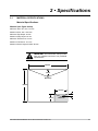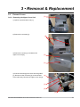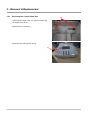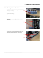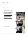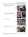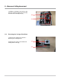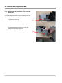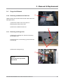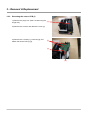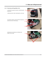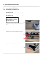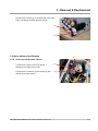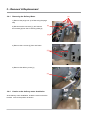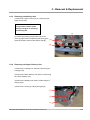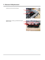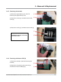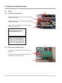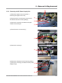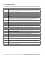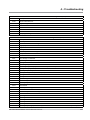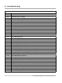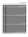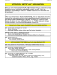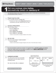
1
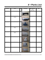
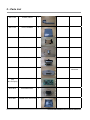
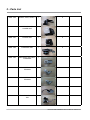
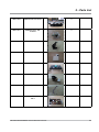
DM100i/DM200i series
Mailing System
Service Manual & Parts List
FORM SDT345A (8-07)
IMPORTANT:
Model and feature availability varies by country. Contact your machine supplier for more information.
This guide covers all models and features. Inclusion within this guide does not guarantee availability of a
particular model or feature within your country.
The title, copyright and all other proprietary rights in this document are vested in Pitney Bowes Limited and no part of it may be reproduced
in any form without the written permission of Pitney Bowes Limited.
The document is for the exclusive use of the person to whom it is issued; its contents are confidential and must not be disclosed to any
third party or used for any purpose other than in the proper conduct of Pitney Bowes Limited's business and it must be returned to Pitney
Bowes Limited immediately upon the person ceasing to be associated with Pitney Bowes Limited.
© Pitney Bowes Limited, 2007
• Contents
• Contents
Page
Service Manual
section 1
Introduction
1.1 - 1.2 - 1.3 - 1.4 - 1.5 - Purpose ............................................................................................
Equipment Covered ..........................................................................
Contents ...........................................................................................
Safety Summary ...............................................................................
Equipment Safety .............................................................................
1-1
1-1
1-1
1-1
1-2
section 2
Specifications
2.1 - 2.2 - Material Specification ........................................................................
Machine Specification .......................................................................
2-1
2-2
section 3
Removal & Replacement
3.1 - 3.2- 3.3 - 3.4 - 3.5 - External Covers ................................................................................
Carriage Unit Related .......................................................................
Purge Unit Related ............................................................................
Lower Delivery Unit Related ..............................................................
PCBs .................................................................................................
3-1
3-4
3-9
3-12
3-18
section 4
Troubleshooting
4.1 - 4.2 - Introduction .......................................................................................
Troubleshooting Tables .....................................................................
4-1
4-1
...........................................................................................................
5-1
Parts List
section 5
Parts List
SDT345A DM100i Series Service Manual & Parts List
• Contents
ii
SDT345A DM100i Series Service Manual & Parts List
Introduction • 1
1 • Introduction
1.1
PURPOSE
This document provides the information necessary to support the installation and site repair of the
DM100i/DM200i Series Digital Mailing System.
1.2EQUIPMENT COVERED
This manual applies to the DM100i/DM200i Series and the kits required for digital mailing system
operation.
1.3CONTENTS
This manual is organised as follows:
● Section 1 – Introduces the manual
● Section 2 – Lists material and equipment specifications
● Section 3 – Presents removal and replacement procedures
● Section 4 – Offers Troubleshooting advice.
● Section 5 – Provides a full parts list.
1.4
SAFETY SUMMARY
Warning messages are used throughout this manual to alert you to potentially hazardous conditions.
These warnings are explained below.
●
●
●
WARNING — calls attention to improper practices that could cause injury.
CAUTION — calls attention to improper practices that could damage the equipment or the material
being run.
IMPORTANT — calls attention to practices that could adversely affect equipment operation, if
instructions are not followed exactly.
You must familiarise yourself with proper procedures and methods before you install, operate or service
the equipment to avoid personal injury or damage to the equipment. If you are responsible for training
service personnel or equipment operators, it is incumbent on you to explain safety precautions to your
students and encourage safety awareness.
The following is a list of general precautions which cannot be over emphasised:
●
HIGH VOLTAGE is present at certain points in the equipment. INJURY or DEATH could result if
you fail to observe safety precautions.
●
Know how to turn off power in the work area and how to summon help in case of emergency.
●
Do not work on equipment under power unless absolutely necessary.
●
When working on a live circuit, use extreme caution. Don’t grasp two sides of a live circuit at the
same time.
●
Always use the right tools for the job.
●
Treat every circuit like a gun which may be loaded. It may not be “live”, but be sure. Check with a
neon tester, a voltmeter, or simply unplug the machine.
SDT345A DM100i/DM200i Series Service Manual & Parts List
1-1
1 • Introduction
●
Use one hand when reaching into a circuit. By keeping one hand free, lethal current is less likely
to pass through vital organs. Observe this rule when connecting or disconnecting plugs or leads,
and when making any adjustments on a live circuit. Don’t underestimate the danger of shock: 1mA
(1/1000 ampere) is uncomfortable; 5 mA (1/200 ampere) is dangerous - the victim may jump back
and be injured; 12 mA (1/83 ampere) causes hand muscles to contract - the victim cannot free
himself; 24 mA (1/40 ampere) has proven fatal; and 100 mA (1/10 ampere) is likely to be fatal.
●
Don’t reach into a circuit with metal tools, or while wearing rings or a watch. Even in low voltage
circuits, a metal object can short circuit two terminals.
●
Don’t bypass safety devices. Three-wire outlets (220/240 VAC) are designed to ground equipment
to make it safe. If a live wire shorts to a grounded frame, the only result is an open fuse. If a live
wire shorts to an ungrounded frame, the frame itself becomes hot and potentially dangerous. A
fuse is a weak link in a circuit, designed to break down before anything else does. The maximum
safe current in a circuit is determined by the designers. Too large a fuse can pass excessive current, damaging expensive equipment. Interlock switches are designed to remove power from a
circuit when an access door, cover or panel is opened. When such a switch is “cheated” or otherwise disabled, a safety device has been bypassed. If you bypass an interlock for service or
diagnostic purposes, use extreme caution.
●
If you use air pressure to clean a machine, use low pressure (30 psi or less) and use eye protection (goggles or face masks).
●
When using solvents or cleaning fluids, make sure ventilation is adequate.
1.5EQUIPMENT SAFETY
Just by walking around, you yourself may carry a threat to the equipment, in the form of a high voltage
electrostatic charge. Your body acts as a giant capacitor which can store large amounts of electricity.
Walking across a rug can charge you with several thousand volts, which can discharge in a spark up
to an inch long.
Digital equipment can be easily damaged or destroyed by static charges. Microprocessors and other
ICs contain tiny transistors not much more than a millionth of an inch across, which operate at 5 to
12 volts. You don’t have to see a spark to ruin an IC — 50 volts is enough. Follow these guidelines to
protect sensitive equipment from static damage:
1-2
●
Ground yourself before reaching into the equipment, or touching any circuit board or other electrical
component. Just touching a doorknob or metal workbench may be enough, but the best guarantee
is to turn the machine off but leave it plugged in, and ground yourself on the chassis, which is
grounded through the three-wire power cord. If you have access to one, bring a grounding strap
and use it.
●
Be careful of rugs — even a few steps can recharge you. Re-ground yourself whenever you’ve
walked away and returned to the machine. Rugs are a major source of static buildup in the
body.
SDT345A DM100i/DM200i Series Service Manual & Parts List
Introduction • 1
WARNING!
Always be sure the equipment is unplugged before you make any attempt
to perform the maintenance outlined in this manual. If you must work on a
"live" machine, note that line potential is present at the power panel and the
motherboard.
CAUTION: DO NOT attempt to adjust key timing parameters in the service menu
unless you have been trained and thoroughly understand what you're doing.
Otherwise you could damage the equipment.
●
Take greater precautions as the objects you handle get smaller. A board in the machine is better
protected than one which is not plugged in; a chip on a board is better protected than one in your
hand.
●
Stay away from metal conductors. The plastic and resin that chips and boards are made of are
much better insulators than metal. It’s most important to keep your hands away from any metal
which contacts the data. In particular, this means the long connector along the bottom of each
board, and the pins coming out of the chips. These signal and data lines are directly connected to
the fragile inner circuits of the chips. When handling a board, try not to touch the connector; when
handling a chip, try not to touch the pins.
SDT345A DM100i/DM200i Series Service Manual & Parts List
1-3
1 • Introduction
1-4
SDT345A DM100i/DM200i Series Service Manual & Parts List
2 • Specifications
2 • Specifications
2.1
Material Specifications
Material Specifications
Material (see figure below)
Minimum Size: 127 mm x 76 mm
Maximum Size: 381 x 330 mm
Minimum Flap Depth: 22 mm
Maximum Flap Depth: 76 mm
Minimum Thickness: 0.18 mm
Maximum Thickness: 9.5 mm
Maximum Stack Height for Mail: 60 mm
IMPORTANT: For best results, always make
sure your material conforms to our published
specifications.
381mm
76mm
Maximum
330mm
127mm
22mm
76mm
SDT345A DM100i/DM200i Series Service Manual & Parts List
Minimum
2-1
2 • Specifications
2.2 Machine Specifications
Size of Base Model:
215mm H x 345mm W x 400mm D
Size of Base Model with Scale:
230mm H x 345mm W x 400mm D
Size of Base Model with Scale and Moistener:
230mm H x 470mm W x 400mm D
Stacker:
The stacker adds 265mm to the width of the system.
Weight:
6.8Kg, approximate.
Power Requirements:
100-240 VAC, 50/60Hz. 1.0A
Communication Ports:
1 USB (B); 1 RJ-11.
Operating Temperature:
4°C to 42°C.
LCD Display: 4 Lines, 20 characters long.
Throughput: Up to 30 letters per minute with no moistener; somewhat less with optional moistener.
Actual throughput will vary depedning on the material used, machine condition, use of moistener,
and the skill of the operator.
Print Resolution: 600 x 300 dpi
Print Image Area: at least 25.4mm x 170mm
Ink Cartridge Life: 2,500 imprints or 22 letters per day, 5 days a week for 6 months.
Tape Sheets: Self-adhesive type, dual tape sheets.
Internal Ad Storage; up to 20.
Departmental Accounting: Number of accounts available based on the amount purchased and
model.
Compliance
It is certified that the digital mailing systen machine complies with the requirements of the Low Voltage Directive 73/23/EEC and the EMC Directive 89/336/EEC. The product was tested in a typical configuration.
For a formal Declaration of Conformity please contact Compliance Engineering on +44 (0)1279 426731.
WARNING: This is a class A product. In a domestic environment this product may cause radio
interference in which case the user may be required to take adequate measures.
2-2
SDT345A DM100i/DM200i Series Service Manual & Parts List
Removal & Replacement
3 • Removal &3 • Replacement
3.0External Covers
3.0.0 Removing the Upper Cover Unit
1) Open the open/closed cover [1].
2) Remove the 2 screws [1].
3) Remove the screw [1], and detach the upper cover unit [2].
[1]
[1]
[2]
[1]
4) Free the harness [2] from the 2 harness guides
[1]. Disconnect the connector [3] on the left side
[4]
of the main body. Remove the upper cover unit [4].
[3]
[2]
[1]
SDT345A DM100i/DM200i Series Service Manual & Parts List
3-1
3 • Removal & Replacement
3.0.1 Removing the Control Panel Unit
[1]
1) Remove the upper cover unit. (See A-1 Removing the Upper Cover Unit)
2) Remove the 4 screws [1].
3) Remove the control panel unit [1].
[1]
3-2
SDT345A DM100i/DM200i Series Service Manual & Parts List
3 • Removal & Replacement
3.0.2 Removing the Lower Cover Unit
1) Remove the upper cover unit. (See A-1 Removing [1]
the Upper Cover Unit)
2) Pull out the lever [1].
3) Remove the 2 screws [1] on the left side of the main body.
[1]
4) Remove the 2 screws [1] on the right side of the main body, and detach the lower cover unit [2].
[1]
[2]
SDT345A DM100i/DM200i Series Service Manual & Parts List
3-3
3 • Removal & Replacement
3.1Carriage Unit Related
3.1.0 Removing the Carriage Unit
Carriage unit consists of the carriage, the guide rail of
the carriage and the carriage motor.
1) Remove the upper cover unit. (See A-1 Removing the Upper Cover Unit)
2) Remove the lower cover unit. (See A-3 Removing the Lower Cover Unit)
3) Turn the gear [1] clockwise with using a screwdriver, to uncap the print head. The cap can be seen from the window [2].
[2]
[1]
CautionNever move the carriage being
capped to prevent the print
head and the cap from damage.
4) Open the ink tank exchange cover, and remove the ink tank.
[1]
5) Remove the print head [1].
[1]
3-4
SDT345A DM100i/DM200i Series Service Manual & Parts List
3 • Removal & Replacement
6) Disconnect the connector [1]. Remove the screw [2] and detach the interface connector unit [3].
[2]
[3]
[1]
7) Remove the screw [1]. Unlock the flexible cable connector and detach the flexible cable [2].
[1]
[2]
8) Remove the screw [1].
[1]
9) Disconnect the connector [1], and remove the screw [2].
[2]
[1]
SDT345A DM100i/DM200i Series Service Manual & Parts List
3-5
3 • Removal & Replacement
10) Slide the carriage [1] to the front, then move the carriage unit [2] to the rear side, and remove the carriage unit [2].
[2]
[1]
3.1.1 Removing the Carriage Drive Motor
1) Remove the carriage unit. (See B-1 Removing the Carriage Unit)
2) Remove the screw [1] and detach the carriage drive motor [2].
[2]
[1]
3-6
SDT345A DM100i/DM200i Series Service Manual & Parts List
3 • Removal & Replacement
3.1.2
Removing the Head Holder Unit
1) Remove the carriage drive motor. (See B-2 Removing the Carriage Drive Motor)
2) Remove the screw [1], and detach the carriage drive rail [2].
[2]
[1]
3) Unlock the hook [1] of the flexible cable cover.
[1]
4) Slide the flexible cable cover [1] to the left side, and detach it. Remove the head holder unit [2].
[1]
[2]
Caution
Do not loosen the tensioner
screw [1] of tension adjustment
for the carriage drive belt must
be made.
[1]
SDT345A DM100i/DM200i Series Service Manual & Parts List
3-7
3 • Removal & Replacement
3.1.3 Adjustment at installation of the carriage drive belt
The tension adjustment of the belt is necessary after the
carriage drive belt is exchanged.
1) Loosen the screw [1].
2) Adjust belt tension at the hook [1] so that
the tension falls in the tolerance.
Tolerance: 1 kg±10%
3-8
[1]
[1]
SDT345A DM100i/DM200i Series Service Manual & Parts List
3 • Removal & Replacement
3.2
Purge Unit Related
3.2.0 Removing the Waste Ink Tank Unit
[1]
Waste ink tank unit consists of the ink tank case and the ink
absorption sheet.
1) Remove the lower cover unit. (See A-3 Removing the Lower Cover Unit)
2) Remove the waste ink tank unit.
[1]
3.2.1 Removing the Purge Unit
1) Remove the carriage unit. (See B-1 Removing the Carriage Unit)
2) Disconnect the 2 connectors [1], and remove the 2 screws [2].
[2]
3) Remove the purge unit [1].
[1]
Caution
Never touch the cap and the
wiper blade.
SDT345A DM100i/DM200i Series Service Manual & Parts List
3-9
3 • Removal & Replacement
3.2.2 Removing the sensor PCB (1)
1) Remove the purge unit. (See C-2 Removing the [1]
Purge Unit)
2) Remove the 2 hooks, and detach the cover [1].
3) Remove the 2 screws [1], connector [2], and
detach the sensor PCB (1) [3].
[1]
[2]
[3]
3-10
SDT345A DM100i/DM200i Series Service Manual & Parts List
3 • Removal & Replacement
3.2.3 Removing the Purge Motor Unit
1) Remove the purge unit. (See C-2 Removing the [1]
Purge Unit)
2) Remove the 2 hooks, and detach the cover [1].
3) Unlock the hook [1], and remove the 2 gear [2]. [3]
4) Disconnect the connector [3].
[1]
[2]
5) Remove the 2 screws [1], and detach the
purge motor unit [2].
[2]
[1]
SDT345A DM100i/DM200i Series Service Manual & Parts List
3-11
3 • Removal & Replacement
3.3
Lower Delivery Unit Related
3.3.0 Removing the Lower Delivery Unit
1) Remove the upper cover unit. (See A-1 Removing the Upper Cover Unit)
2) Remove the lower cover unit. (See A-3 Removing the Lower Cover Unit)
Caution
Do a pressure release of the
delivery unit prior to removing
the lower delivery unit.
[1]
3) Remove the screw [1] on the left side of the main body.
4) Remove the 2 screws [1], and detach the tray [2].
[2]
[1]
5) Remove the screw [1] on the left side of the main body.
[1]
3-12
SDT345A DM100i/DM200i Series Service Manual & Parts List
3 • Removal & Replacement
6) Remove the screw [1] on the right side of the main body, and detach the lower delivery unit [2].
[2]
[1]
3.4 Upper delivery Unit Related
[2]
3.4.0 Removing the Encoder Sensor
1) Remove the upper cover unit. (See A-1 Removing the Upper Cover Unit)
2) Remove the connector [1] and screw [2], and detach the encoder sensor.
SDT345A DM100i/DM200i Series Service Manual & Parts List
[1]
[3]
3-13
3 • Removal & Replacement
3.4.1 Removing the Delivery Motor
[3]
1) Remove the purge unit. (C-2 Removing the purge unit)
2) Disconnect the connector [1], and remove the harness [2] from the 5 harness guides [3].
[1]
[2]
3) Remove the 2 screws [1] from rear frame.
[1]
4) Remove the delivery motor [1].
[1]
3.4.2 Caution at the delivery motor installation
At the delivery motor installation, locate the motor so that the
harness come to the position as shown.
3-14
SDT345A DM100i/DM200i Series Service Manual & Parts List
3 • Removal & Replacement
3.4.3 Removing the delivery belt
1) Remove the upper cover unit. (A-1 Removing the Upper Cover Unit)
Caution
Do a pressure release of the
delivery unit prior to removing
the delivery belt.
[3]
2) Loosen the screw [1] temporarily and fix the
screw [1] again while compressing the spring [2] to [1]
lower the tension. Remove the delivery belt [3].
[2]
3.4.4 Removing the Upper Delivery Unit
1) Remove the carriage unit. (See B-1 Removing the Carriage Unit)
2) Remove the lower delivery unit. (See D-1 Removing the Lower Delivery Unit)
3) Remove the delivery belt. (See E-4 Removing the delivery belt)
4) Remove the screw [1], belt [2], and gear [3].
[2]
[1]
[3]
SDT345A DM100i/DM200i Series Service Manual & Parts List
3-15
3 • Removal & Replacement
5) Remove the rail [1] and bushing [2].
[2]
[1]
6) Remove the 4 screws [1], and detach the upper delivery unit [2].
[2]
[1]
3-16
SDT345A DM100i/DM200i Series Service Manual & Parts List
3 • Removal & Replacement
[1]
3.4.5 Removing the encoder
[2]
[1]
1) Remove the upper delivery unit. (See E-5
Removing the Upper Delivery Unit)
2) Remove the screw [1], and detach the encoder cover [2].
[1]
3) Remove the screw [1], and detach the encoder [2].
[2]
[1]
[2]
Caution
[2]
Holding the encoder, with hand,
hold it as shown.
[1]
3.4.6 Removing the Sensor PCB (2)
1) Remove the encoder. (See E-6 Removing the encoder)
2) Remove the 2 screws [1] and connector [2],
and detach the sensor PCB (2) [3].
[1]
[2]
[2]
[3]
[3]
SDT345A DM100i/DM200i Series Service Manual & Parts List
3-17
3 • Removal & Replacement
3.5
[3]
[3]
PCBs
3.5.0 Removing the Main PCB
1) Remove the upper cover unit. (See A-1 Removing[1]
the Upper Cover Unit)
[1]
2) Disconnect the all connector [1] and flexible cable[4]
[2] on the main PCB.
3) Remove the 3 screws [3] on the main PCB, and [2]
detach the main PCB [4].
[4]
[2]
Caution
Unlock the connector when
removing flexible cable.
Caution
Dispose of the lithium battery
according to local regulations.
The lithium battery for the main
PCB is a non-replaceable part.
[3]
[3]
3.5.1 Removing the Modular PCB
1) Remove the main PCB. (See F-1 Removing the Main PCB)
2) Remove the connector [1] and the 3 screws [2] [2]
and detach the modular PCB [3].
[2]
[1]
[1]
3-18
SDT345A DM100i/DM200i Series Service Manual & Parts List
3 • Removal & Replacement
[1]
3.5.2 Removing the DC Power Supply Unit
1) Remove the upper cover unit. (See A-1 Removing the Upper Cover Unit)
2) Disconnect the 2 connectors [1], and remove the harness from the harness guide [2].
3) Remove the screw [3], and detach the open/
closed cover sensor [4].
4) Disconnect the 2 connectors [1].
[2]
[4]
[3]
[1]
5) Remove the screw [1].
[1]
6) Remove the harness from the harness guide [1].
7) Remove the screw [2], and detach the DC power [3]
supply unit [3].
[1]
[2]
SDT345A DM100i/DM200i Series Service Manual & Parts List
3-19
3 • Removal & Replacement
3-20
SDT345A DM100i/DM200i Series Service Manual & Parts List
4 • Troubleshooting
4 • Troubleshooting
4.0
Introduction
This chapter explains how to troubleshoot the DM100i and DM200i. It includes troubleshooting charts and a list
of error codes and their meanings.
4.0.1 General Troubleshooting
Before troubleshooting the equipment, check that the customer's material falls within the specifications
published in Chapter 2 of this manual. You can often trace frequent feed failures to substandard or out-of-spec
material or to improper feeding techniques on the part of the operator.
If the problem involves poor print quality, run a test print (Option > Scroll Down > Maintenance > Printer
Maintenance Mode > Test Print) and evaluate the sample. If the test print is not acceptable, select No,
Clean Nozzle when prompted. This action automatically runs the manual maintenance functions. Repeat the
maintenance procedure if necessary.
4.0.2Error Messages
The system can display a number of error messages that describe fault conditions. Table 4-10 is a general
summary of these messages arranged by their most significant digits. Tables 4-11 onwards list many error
codes.
4.2
Troubleshooting Tables
Tables 4-1 through 4-9 present troubleshooting information for the following problems:
•
•
•
•
•
•
•
•
•
•
Power On and Initialization Faults
Display Faults
Transport Faults
Tape Feeder Faults
Printing Faults
Carriage Movement Faults
Moistener Faults
Postage By Phone Errors
Modem Faults
Integrated Scale Faults
SDT345A DM100i/DM200i Service Manual & Parts List
4-1
4 • Troubleshooting
Table 4-1 Power ON and Initialization Faults
Errors
Checkpoints
Possible Causes/Solutions
Mailing machine
is connected
to power, but
control panel
LED is off, no
initialization, no
display, no printer
sounds.
Does the cord show obvious signs of wear?
Does another cord work?
Replace the power cord.
Is the power cord connected to a functioning
wall outlet?
Check wall outlet. Is it switch-controlled? If
machine is connected to a power strip, try
connecting it to a known good wall outlet.
Defective power supply board. System dead.
Check for 27V (to feeder, transport motor, and
print head) and 5V (to control panel, main
logic). Check wiring to an connection at Main
Logic Board, J9.
System starts to initialize, but hangs.
LED is green. No printer noise (no printer
initialization). Screen stuck on “Initializing...
Please Wait...”
Verify that all interlocks are closed. Power
supply. Check wiring from PS board to Main
Logic Board, J14.
An error occurred during printer initialization
process. This is a CM/PM initialization timeout.
•
If this occurs during install, check that all
shipping tape has been removed from unit.
•
Unplug power cord from unit and then wall
outlet. Wait three minutes. Plug cord into
unit and then into machine. If this problem
occurs every time machine is power
cycled, replace it.
•
Check that ink cartridge cover is closed.
Code 010E
displays.
“Printer Fault”
error displays.
Error 2447.
Does Error 2447 display?
The system failed to detect the print carriage.
Check ribbon cable from print head to J13 on
Main Logic Board. Problem could be caused
by bad connection, ribbon cable, print head
controller board (sealed in carriage assembly)
and print head.
“System Fault”
error displays.
Error 2554.
Does Error 2554 display? 2304?
The system failed to detect the Postal Security
Device (PSD). Communications with PSD
failed. Is PSD present? Check that it is properly
seated and making full contact with board.
2304 is a communication timeout error.
1/2 “Jam Lever
Open” and 2/2
“Clear Transport”
errors display.
4-2
If these errors display when the jam lever is
closed and the transport is clear, the sensor
board may be suspect.
Check sensor board and wiring to Main Logic
Board, J8.
SDT345A DM100i/DM200i Service Manual & Parts List
4 • Troubleshooting
Table 4-2 Keyboard and Display Faults
Fault
Checkpoints
Possible Causes/Solutions
Keyboard
failure. Does not
respond.
Wiring from keyboard to J4. Keyboard PCB.
Poor connection at keyboard, wiring and
connection at Main Logic Board, J4.
No display.
Machine may be in sleep mode. Is front panel
LED orange?
Press any key to wake unit.
Check display contrast.
Adjust display contrast as required.
Machine not getting power.
Power cord not plugged in. Power cord plugged
into a switched or defective outlet. Try another
wall outlet. If unit is plugged into a power strip,
move the power cord to a functioning wall
outlet.
No display, front panel LED off, but print head
initializes at start up.
Check connector J4.
See Table 4-1 for power ON an initialization
faults.
Display does not
change.
Meter appears to be “stuck” on the same
display for an extended period of time.
SDT345A DM100i/DM200i Service Manual & Parts List
Power cycle the meter to reboot and start over.
4-3
4 • Troubleshooting
Table 4-3 Mailing Machine Transport Faults
Fault
Checkpoints
Possible Causes/Solutions
Operator Error.
Operator may be feeding piece improperly.
Instruct operator to position envelope top edge
against rear wall and slide it to right.
Interlocks.
Are cartridge access cover and lower transport
closed?
An error message should display if either
interlock is open.
Transport fails to
drive.
Transport drive motor and drive components.
Test using service diagnostics. Also check
harness and connection at J7.
Drive belts damaged or improperly tensioned.
Check drive belts and tensioners.
Drive shaft fails to turn. Drive shaft is binding.
Check pulleys. Make sure they are securely
mounted on shaft.
Transport drive belt.
Check belt for proper tracking. Check for wear,
glazing, cracks, etc.
Lower transport problems.
Make sure lower transport locks in operating
position and that idlers contact transport
drive belt. Check that all idlers are correctly
positioned and turn freely.
Frequent jams.
Debris in transport; envelope thickness out of
spec.
Check transport, clean as required. Maximum
envelope thickness is 9.5mm.
Frequent skews.
Operator error.
Instruct operator to make sure top edge of mail
piece is against registration wall. Cusomer
should not hold on to mail as he or she feeds it
onto deck. If oversized mail piece, use a tape
strip.
No printing
occurs.
Envelope blank, no errors.
Check ink cartridge. Perform purge. Clean
electrical connections; check electrical
connections.
Transport
fails to drive,
(continued).
4-4
SDT345A DM100i/DM200i Service Manual & Parts List
4 • Troubleshooting
Table 4-4 Printing Faults
Errors
Checkpoints
Possible Cause/Solution
No print out of
box.
In some cases, the print head may dry out or
be cold from shipment. This could result in a no
print condition. Allow the system to warm up to
room temperature. Follow steps at right.
1. Complete install.
2. After install is complete, remove ink
cartridge and print head.
3. Make sure tape has been removed from
bottom of print head and tab has been
removed from ink cartridge,
4. Check that ribbon cable from carriage
assembly to J13 is intact and properly
connected.
5. Clean the gold connectors on the side of
the print head with a pencil eraser.
6. Install the print head and ink cartridge.
7. Check the capping station. Clean if
necessary.
8. Test print quality. Test and purge
procedure is available through the user
(OPTIONS). From the user menu, press
OPTIONS > Scroll down > Advanced
Features > Maintenance Mode > Printer
Maintenance > Test Print. See illustration
below.
9. If print quality is poor, perform up to three
“C” purges. Then perform a “D” purge.
Poor print quality:
gaps and voids.
Purge may be required. Test and purge
procedure is available through the user
(OPTIONS). From the user menu, press
OPTIONS > Scroll down > Advanced Features
> Maintenance Mode > Printer Maintenance >
Test Print.
NOTE: For a poor print issue that will not
clear with a basic purging, perform the
printhead replacement procedure. With the
system running, open the print head/ink
access cover. Select “Replace Print Head.”
Physically remove the printhead and
reinstall it following the prompts.
GOOD
BAD
Figure 4-1 Print Test Patterns
If the test pattern shows gaps or voids, purge
the printer nozzles and retest. If little or no
improvement is noted, you may repeat the
purge up to five times total.
SDT345A DM100i/DM200i Service Manual & Parts List
4-5
4 • Troubleshooting
Table 4-4 Printing Faults (Continued)
Errors
Checkpoints
Possible Cause/Solution
Poor print
from used ink
cartridge.
Follow steps at right.
Remove the printhead and check for bent pins.
Pins are normally angled downward.
Make sure printhead is correctly installed.
Check printhead harness and connection at
J13.
If purges fail to correct the problem, and the ink
cartridge is not empty, replace the printhead.
If this fails to correct the problem, there may be
a problem with the print head carriage board.
This requires replacement of the print head
carriage assembly.
Print is not
clean and crisp;
smearing or
spotting evident.
Ink supply is
okay.
Wiper blade. Also check the “wiper.” It is easily
replaceable.
Check the wiper blade for excess ink
accumulation. Clean as required. Replace
wiper wiper if necessary.
Does a purge correct the problem?
If needed, purge and run a test print.
Is the carriage moving normally so that wiping
occurs?
Check carriage movement and correct any
problems. See table 4-5
Is the printhead harness properly connected at
J13?
Make sure it is locked in position.
No print, red or
partial print.
Possible print head controller (PHC) failure.
Partial, streaked
or Incomplete
print.
Wiper and/or capping station may be
contaminated with excess ink. Purge may be
required.
Clean wiper and capping station. Perform a “C”
purge, then a “D” purge.
Customer
complains that
ink usage is high.
Ink yield is based on usage. Higher usage
prolongs cartridge life because more ink is used
during maintenance than printing.
Is machine in seal-only mode? This mode
disables printing.
Is the customer performing manual purges?
This increases ink consumpton.
Check for bent pins
How often does the customer use the meter?
When was the ink cartridge installed?
Is the customer printing ads? This increases ink
usage.
Is the customer printing reports? This increases
ink usage.
Make sure tape is off print cartridge bottom.
Check for bent pins. These are behind print
head (see figure) and are angled downward.
4-6
Figure 4-2 Contact Pins
SDT345A DM100i/DM200i Service Manual & Parts List
4 • Troubleshooting
Table 4-4 Printing Faults (Continued)
Errors
Checkpoints
Possible Cause/Solution
Poor print with
new ink cartridge.
Purge.
Perform a “B” purge and run a test print.
Normally two such purges will result in a
clear, crisp print. If not, you can try up to three
more purges. If these fail, the print head, print
head ribbon cable and connection at J127 are
suspect. See instructions for Poor print from
used ink cartridge.
Print head/ink
tank not detected.
SDT345A DM100i/DM200i Service Manual & Parts List
1. Reinstall print head and ink cartridge.
Check for bent pins when you do this.
Make sure cap was taken off printhead
and tape removed from cartridge. Check
that print head is snapped into position.
2. Reboot.
3. Check PH ribbon cable and connection at
J13.
4. Print head may be suspect.
4-7
4 • Troubleshooting
Table 4-5 Print Carriage Faults
Errors
Checkpoints
Possible Cause/Solution
PS1 fails to sense envelope or tape lead edge.
Check for debris in transport path.
Carriage drive belt.
Inspect belt and pulleys. Check that belt is
centered on pulleys and fully engages loop on
carriage.
Carriage drive rails.
Check that carriage assembly is not binding
on rails. Assembly should move freely.
Purge motor.
If the purge motor fails to turn clockwise with
the carriage assembly in the home position,
the printhead lock and cap will remain up,
preventing movement of the carriage. Check
the harnesses from the purge motor to
connectors J5 and J9 on the Main Logic Board.
Error 2443.
And grinding noise.
Indicates carriage motor failure or wiring
problem. System locks when error message
is cleared. See Carriage drive stepper motor
above.
Error 2442.
Printer Fault.
Possible problem with cap motor or sensor
located in purge unit. System may lock when
error is cleared. Check wiring to Main Logic
Board, J5. In addition, check purge motor and
wiring to Main Logic Board, J9.
Print carriage
fails to move from
home to print
position.
NOTE: It is
normal for the
print head to
move back to the
home position
if an envelope
or tape is not
sensed by PS1
for 15 seconds.
4-8
SDT345A DM100i/DM200i Service Manual & Parts List
4 • Troubleshooting
Table 4-6 Moistener Faults
Problem
Possible Cause
Solution
Envelopes don’t
seal.
Incorrect feeding.
Check that operator is sliding envelope flap under blue
edge of feed deck. If this is not done, moistener can’t wet
flap.
Low sealant level.
Check sight glass on moistener tank. If level is low, add E-Z
Seal® until it reaches bottom of fill hole.
Dry moistener brush.
Try wetting moistener brush. If brush drys out quickly,
replace moistener wick.
Dirty moistener brush.
Remove brush, clean in plain water and rinse thoroughly.
Worn moistener brush.
Replace moistener brush.
Table 4-7 Miscellaneous Faults
Problems
Checkpoints
Lock Code
Customer forgot
meter lock code.
Possible Cause/Solutions
Go to Enter Lock code screen. Type in 6946Refill. This will take you to the service mode.
Press Clear. This takes you to the main menu.
Lock Code will override Supervisor Code.
“Ink Tank Access
Cover Open”.
Access cover.
Close access cover. If this doesn’t correct
problem, check sensor flag. Sensor must be
blocked when cover is closed. If flag is okay,
check wiring and connection at Main Logic
Board, J11.
System is noisy.
Lubrication may be required.
Use teflon/silicone grease on feeder gear
shafts if there is noise. Also use on white
tension idler rollers if they make a high
squealing noise.
SDT345A DM100i/DM200i Service Manual & Parts List
4-9
4 • Troubleshooting
Table 4-8 Modem/Connection Faults
Problem
Possible Cause
Solution
Machine fails
to connect to
Postage By
Phone Data
Center: No dial
tone.
System not connected to working
analog phone line.
1. Make sure the phone cord is firmly connected to a
single line analog phone jack. The term analog phone
line refers to a RJ11C or RJ11W compatible (single
line) telephone wall plug typically used for a residential
phone, analog dial-up computer modem or facsimile
(fax) machine.
2. Insure the dialing prefix is set properly if needed.
3. Verify whether a delay (pause) is required in the dialing
sequence. For example, a pause may be required after
the prefix.
4. Verify the correct PB Phone No is entered0845 912 2401.
5. There may be a problem with the meter serial number
not being recognized by PBP. Are there any error
codes displayed? Check the Error Log before and after
attempting the connection.
6. There may be telephone line noise or attenuation
causing the line to drop. Trying a different phone
number may help.
7. Connect an analog telephone to the line and verify that
you can dial out and hear clearly on the line.
8. If a line splitter is used, try removing it and connect
directly to the wall jack.
9. If the customer is using DSL, try connecting through
the DSL Analog/Digital Filter while no one is on the
internet.
10. Could not connect because of V.42 connect time out.
This can happen with satellite transmissions. Slowing
down the modem often resolves this. Please see
Changing the Modem Speed, next page.
4-10
SDT345A DM100i/DM200i Service Manual & Parts List
4 • Troubleshooting
Table 4-8 Modem/Connection Faults (Continued)
Problem
Possible Cause
Solution
Machine fails
to connect tp
Postage By
Phone Data
Center: No dial
tone.
Changing the modem speed:
Version 8.60 Meters are built with a default Modem
Initialization String setting, as follows:
ATE0&K0M1X4W2S9=50S7=90^M
Using the following Key sequence will take you to the
screen which allows you to edit this string:
Options > Connect to Data Centre > Phone Parameters >
Modem Parameters
Select Modem String
Select Continue
Select Edit Options
Then, using the Move Cursor Left and Move Cursor Right
soft Keys, edit the string so it looks like:
ATE0&K0M1X4W2S9=50S7=90+MS=V34^M
Add the ‘+MS=V34’ to the string; it MUST be placed before
the ‘^M’
NOTE: Special characters like + = ^ can be found on the
QWERTY Keyboard. For + use G, for = use A, for ^ use
B. Version 11.14 uses the new string. If problems are still
encountered try
V32 14400 baud
V22 2400 baud
Once the string looks correct then:
Select OK
Select Accept
Select Done
Modem setup incorrect.
Check that modem setup is correct. Go to OPTIONS and
scroll to CONNECT-DATA CENTRE. Is tone/pulse setting
correct? Is a dial prefix required to get an outside line? Is
PbP number correct? Other modem parameters OK?
Faulty modem.
Check that modem is properly seated on main logic board
and that connection between J2 on modem board and J21
on main logic board is sound.
SDT345A DM100i/DM200i Service Manual & Parts List
4-11
4 • Troubleshooting
Table 4-9 Integrated Scale Faults
Problem
Possible Cause
Solution
Scale problems at
time of install.
The scale line is not showing or
an error code (e.g., 1103, 11F6)
displays
Put in for a download.
Try steps at right.
1. Try uploads and downloads.
2. Push down hard on the scale, then reboot.
3. Remove the rubber feet on the scale, push down on
scale and reboot.
4. Check that RS232 connector and pins are okay.
5. Check harness from DB-9 connector to J107 on Main
Logic (Controller).
6. If this fails, place in the Print Head Queue.
7. Check DLA. If the scale feature dowloaded, replace
the scale.
8. If no scale feature downloaded, place in the print head
queue.
Scale problems
after install.
If the scale has been working and
the scale line shows but nothing
else, or the scale line shows with g,
but no zeroes, try steps at right.
1. Push down hard on the scale, then reboot.
2. Remove the rubber feet on the scale, push down on
scale and reboot.
3. Check that RS232 connector and pins are okay.
4. Check harness from DB-9 connector to J3 on Main
Logic (Controller).
5. If this fails, replace the scale but DO NOT put into Print
Head queue.
Weight over
capacity.
User attempted to weight an
item that exceeds the maximum
capacity of the platform they
ordered.
See error 1103 if this is not the case. If these steps don’t
work, follow the local process to have the DLA reset.
Advise the customer to perform a download in 24 hours.
Rate manager not
initialized.
Check the order to verify the weight
capacity was ordered.
Follow the local process to have the DLA reset. Advise the
customer to perform a download in 24 hours.
Scale does not
function; unable
to rate mail on
scale.
Is scale seated properly?
Reseat scale. Is serial port set to “Attached Scale?” Check
serial port wiring to Main Logic Board, J3. Is rating feature
enabled?
Auto scale
function does not
work.
Auto scale may be turned off. Scale
not set up properly.
Enter menu and make sure auto scale function is ON.
4-12
SDT345A DM100i/DM200i Service Manual & Parts List
4 • Troubleshooting
Table 4-10 Common Error Messages
Error
2003 and 2004
220C
24A4 or 24A5
2442
DE06 or DE14
Low Sector Error
010E
Action
Startup error. Reboot system.
Time out error. Reboot system.
Reboot. Leave system off for a minimum of one minute. A replacement print head will not resolve
these errors.
Reboot. Leave system off for a minimum of one minute.
Attempt to connect to Postage By Phone was unsuccessful, Check PbP for any flags that may be
on the account or any budgets listed for the customer’s refill amount. Once the flag or budget is
found, proceed accordingly.
Reboot.
Error occurred while trying to initialize printer. If this occurs during install, check that all shipping
tape has been removed from the system.
Remove the power cord from both the wall outlet and the machine. Wait three minutes and
reconnect power.
Make sure the ink cartridge cover is closed.
0112
Ink carriage motor timing area. Usially occurs along with 2443 error when the system is rebooted.
See instructions for error 2443.
0802
The print carriage is not moving correctly or is jammed. This may also happen during refills.
Reboot for thirty seconds. If this fails to clear the error, reboot for three minutes. If the problem
persists, see Table 4-7 for addtional troubleshooting information.
1103
Weight capacity was not downloaded. Check the order to verify that weight capacity was ordered.
Follow local process to have DLA reset. Advise customer to perform download after 24 hours.
11F6
The system is not processing rates correctly. Check the order to verify that appropriate rating
feature was ordered. Follow local process to have DLA reset. Advise customer to perform
download after 24 hours.
200C
Real time clock error — out of range. If this occurs during out-of-box setup, reboot the system.
Press continue to bypass the current clock time and complete the install process. Change clock
time after installation is complete.
If this occurs after setup, confirm the current system time by printing a report. Attempt to update
the system time from the options menu and then reboot the system.
200D
Bad status message received from PbP. Confirm the system is installed on PbP and try to
reconnect. Also confirm with PbP that funds are available for the customer.
220C
Invalid meter graphics were detected. Try rebooting.
24A3
Print head not at correct temperature. Is the system located near a heater, hot air vent or unusually
warm area? Move to cooler area. Try rebooting to clear message. If unable to clear message,
print head is suspect.
2443
Ink carriage motor or sensor error. Grinding noise may also be heard. Check the capping station
area to see if the capping station is broken or loose. If loose, try snapping it back into position. If
this fails, replace purge unit.
2494
Ink tank communication error. This error usually occurs when a new ink cartridge is installed.
Remove the ink cartridge and reinstall it. If this clears the error, install a new ink cartridge. If not,
reboot.
2544
Communication with the vault failed. Withdraw the system from service. You will not be able to
remove funds.
2544/220C
Communication with the vault failed. Reboot the system for 30 seconds. If this fails, reboot the
system for three minutes. This shoule clear the error.
SDT345A DM100i/DM200i Service Manual & Parts List
4-13
4 • Troubleshooting
Table 4-10 Common Error Messages (Continued)
Error
DE00
Location Code
Required
EMD
Action
When trying to connect with the Data Center, either PbP is not set up to communicate with the
meter or there is some other type of network problem.
1. Confirm the meter is installed at PbP, that the cusomer has not reached his or her credit limit,
and that there are funds available to download.
2. If PbP is okay, there may be a network communication problem.
3. Make sure the meter is installed on the customer’s account.
4. Make sure the customer is not attempting to use a credit card.
5. Reboot the system for 30 seconds. If tis fails, reboot the system for three minutes.
6. If the meter was installed at PbP, have the customer change to the local AT&T number and
attempt to connect again.
7. You must reboot after every DE00 error.
Location code not installed during setup.
The meter can’t confirm that its memory is working. Withdraw the system from service. If funds are
in the meter, flag as QAR (Question of Accurate Registration).
Invalid User ID/
Password
Usually Occurs during install.
1. Press CLEAR.
2. Reboot for 30 seconds.
3. If the display returns to ENTER AMOUNT TO ADD TO METER, press CLEAR.
4. Select RETURN TO START to begin the install over again.
Link Negotiation
Failed
Check that system is connected to an analog line. Try using 1-800-590-4857, 1-866-297-8025 or a
local access number.
1. Reboot system.
2. Press CLEAR when display prompts: DO YOU NEED TO ENTER A NUMBER TO REACH AN
OUTSIDE LINE?
3. Select QUIT INSTALL and YES/ENTER to confirm. Display prompts: NOT AUTHORIZED.
4. Press OPTIONS.
5. Press PAGE DOWN (SCROLL) two times.
6. Select Connect — Data Center.
7. Select Phone Parameters.
8. Select Change PB Phone Number.
9. Press YES.
10. Enter the alternate phone number an select OK.
11. Reboot system. Display prompts: DO YOU NEED TO ENTER A NUMBER TO REACH AN
OUTSIDE LINE?
12. Retry the connection again.
Low Sector Error
Reboot.
010E
Error occurred while trying to initialize printer. If this occurs during install, check that all shipping
tape has been removed from the system.
Remove the power cord from both the wall outlet and the machine. Wait three minutes and
reconnect power.
Make sure the ink cartridge cover is closed.
Meter not
Authorized
Message
4-14
Same as Link Negotiation Failed error. See table entry above.
SDT345A DM100i/DM200i Service Manual & Parts List
4 • Troubleshooting
Table 4-10 Common Error Messages (Continued)
Error
Action
No Dial Tone
See Table 4-8.
Print Head/Ink
Tank not Detected
See Table 4-4.
Rate Manager Not
Initialized
See Table 4-9.
Weight Over
Capacity
See Table 4-9.
37B6
2544, 2443
Error on DM400c. Happens when transport is opened? Clear envelopes from paper path
and reboot.
Errors during bootup - The PSOC is communicating with the PSD and it is taking too
long. Solution - Leave error up for two minutes, then reboot.
2546
Reboot to clear if softkey does not work.
372A
Feeder error with C4 envelope.
2482 or 248B
No Paper. Cause: Operator inserted a mail piece then pulled it back out and then put it in
again during a batch.
DE1D
Reboot to resolve.
2412
Tape ran out and last tape did not print.
25xx
iButton.
23xx
PSOC.
248B
Mail jam caused by stream feed.
SDT345A DM100i/DM200i Service Manual & Parts List
4-15
4 • Troubleshooting
Table 4-11 Motion Control Processor (MCP) Related Error Codes (16xx Codes)
Error
Description
1600
No Error
1601-1627
Reserved
1628
Failed to Feed
1629
Printer Not Ready
162A
TAR2 Exit Jam
162B
Printer Error
162C
Transport Jam
162D
TAR1 Exit Jam
162E
Tape Jam
162F
Printer Over run
1630
Trip Jam
1631
Mail piece too thick (jam)
1632
Print Head Fire Timeout
1633
Printer Not Ready during Tape
1634
Printer Error during Tape Printing
1635
A ‘Run “ail” operation was attempted with mail in the transport area.
1636
The Power Stacker is Full
1637
Skewed mail piece (reported by DM400 only)
1638
Mailpiece Hold Error (Differential Weighing)
1639
CSpark Tape Stream Error
163A
Jam at hand-off to the WOW Module
163B
Mail Piece too long - happens if the WOW sensor signifying that the piece is in position to weigh is
blocked and the WOW entry sensor is still blocked
163C
WOW Done message not received by MMC in specified time (WOW Weighing timeout) - a 5 second
timeout on the handshake with the weighing module.
163D
WOW Re-Zero Error
163E
WOW Weight Error
163F-1658
4-16
Reserved
1659
Non-volatile Memory Failure
165A
Invalid Parameter Checksum in NVM
165B
Invalid Cycle Count Checksum in NVM
165C
Invalid Jam Count Checksum in NVM
165D
MCP Reset due to Watchdog Timeout
165E
Bad Profile Command
SDT345A DM100i/DM200i Service Manual & Parts List
4 • Troubleshooting
Table 4-11 Motion Control Processor (MCP) Related Error Codes (16xx Codes) Continued
165F
Invalid Motor State
1660
Invalid Position Move
1661
Error erasing flash memory for download
1662
Error saving flash memory after download
1663
Servo Position Error
1664
I2C Bus Error
1665
DM360 Feeder reported a Power On Self Test error
1666
DM360 Feeder Communications Timeout
1667-167F
Reserved
1680
Flash File System (FFS): MCP profiles are not Loaded (don’t exist in FFS)
1681
Flash File System (FFS): Requested Profile Group Doesn’t Exist in MCP Profile
1682
Flash File System (FFS): Invalid binary Profile
1683
Invalid “default” Switch Condition
1684
The MCP Reset due to a Watchdog Timeout
1685
The MCP reset due to an error condition (e.g., ESD)
1686
The mail run was terminated by specified condition
1687
The internal state “stack” overflowed (too many pushes)
1688
The internal state “stack” underflowed (too many pops)
1689
Clear of Debit Operation Occurred before Mailrun
168A
The WOW isn’t Present but Should Be
168B
The MMC is not Responding
168C-168D
168E
168F-1696
Reserved
The WOW Unable to Weigh – Weight Unstable
Reserved
1697
A Sealant Out Condition Exists
1698
A Tape Out Condition Exists
1699-16A1
Reserved
16A2
Interlock Cover Open Event
16A3
Interlock Cover Closed Event
Error
Description
16A4-16AA
Reserved
16AB
Power Stacker Full
16AC
WOW Error
16AD
The Weight Break Table Entries were Sent out of Sequence
16AE
Negative Weight Calculated
16AF
Weight not Valid for Mail Type
16B0
Weighing Error (unstable - maximum number of samples exceeded)
16B1
Weighing Error (no tare achieved - maximum number of samples exceeded)
16B2
WOW asked to weigh without calibration (calibration required)
16B3
Compute Rezero is Outside +/- 20 grams
16B4
Compute Rezero is Outside +/- 2 grams
16B5
Requested Operation Cannot be Performed in the Current State.
SDT345A DM100i/DM200i Service Manual & Parts List
4-17
4 • Troubleshooting
Table 4-11 Motion Control Processor (MCP) Related Error Codes (16xx Codes) Continued
16B6
Feeder Hardware Not Detected
16B7
The Requested Operation is invalid
16B8
The Feeder has not enumerated in a timely fashion
16B9
The firmware update has failed.
16BA
No firmware has been installed in the UIC.
16BB-16FD
4-18
Reserved
16FE
Branch-to Profile or Segment doesn’t exist
16FF
Requested Profile not available to be run
SDT345A DM100i/DM200i Service Manual & Parts List
4 • Troubleshooting
I-Button Specific PSD Error Codes Group 2 (21xx):
This class of errors is reported by the Janus UIC when there are image generator errors.
Table 4-12 DM100i/DM200i Image Generator Errors (22xx)
Error
Description
2201
Font, graphic, barcode, or text ad component had wrong schema version
2202
Too many “indicia” components in the region map OR too many “town circle” components in the region
map(s).
2203
Wrong state to do the requested operation
2204
Someone requested a change in the date duck state when there is no date field
2205
Someone requested a change in the EB duck state when there is no Entgelt Bezahlt
2206
Someone requested a change in the PIN duck state when there is no PIN field
2207
Someone requested a change in the TL/TC duck state when there is no town line field and no town
circle
2208
The region maps weren’t numbered consecutively OR the id of the first region map wasn’t 0 (zero) OR
the region map didn’t contain an indicia component or a permit component or a tax graphic component
or a date/time component OR the region map had both a normal/low indicia component and a leading/
lagging indicia component OR the region map had both a normal indicia component and a low value
indicia component OR the region map had a combinations of indicia and/or permit and/or tax graphic
and/or date/time components
2209
Someone tried to set the indicia type to “low” when there is no low value indicia graphic component
220A
IG_Reload was called. Now IG_LoadIndicia, IG_LoadPermit, IG_LoadTaxGraphic, IG_LoadAdInscr or
IG_LoadDateTime must be called before calling one of the “duck” functions or IG_LoadStaticVCRs or
IG_LoadVariableVCRs. Similarly IG_LoadReport must be called before IG_LoadNextReportPage.
220B
Region map contained an invalid component type
220C
Someone called IG_LoadIndicia or IG_LoadAdInscr when there is no indicia region map
220D
Someone called IG_LoadPermit when there is no permit region map
220E
Someone called IG_LoadTaxGraphic when there is no tax graphic region map
220F
Someone called IG_LoadIndicia when there is no indicia type selected
2210
Someone called IG_LoadPermit when there is no permit selected
2211
The blob was missing data for a set of VCRs OR the name strings was missing from the TC graphic and
it’s needed
2212
The data for a graphic component was missing from the component structure given to IG_Powerup or
IG_Reload or IG_SetIndiciaType
2213
Font used by a text ad is missing OR font used by one or more VCRs is missing OR 1D barcode font is
missing
2214
A region’s or VCR’s starting point (column or row) and/or ending point (column or row) isn’t within the
print area
2215
The width and/or height of a graphic or font is zero OR the max width and/or max height of a region is
zero OR the width/height of a graphic is greater than the max width/height of the region that the graphic
goes in
2216
The address of the graphic or font character is zero OR the size of the graphic or font character is zero
2217
The compressed data had a command byte with a byte count of zero
2218
When the image data is decompressed, the graphic is bigger than the given height and width
2219
The number of VCRs defined in the register groups doesn’t match the number of VCR location records
OR too many VCRs have been defined
221A
A register group or text ad line or 1D barcode field has an unknown justification value.
SDT345A DM100i/DM200i Service Manual & Parts List
4-19
4 • Troubleshooting
Table 4-12 DM100i/DM200i Image Generator Errors (22xx) Continued
221B
A register group has a field size that is too big OR the number of VCR definitions for a graphic doesn’t
match the sum of all the register field lengths for the graphic OR the total number of VCRs for a region
map is more than the max allowed.
221C
The text ad works out to be wider than the ad region
221D
The text ad works out to be taller than the ad region
221E
The ad area doesn’t have any space except for the required border around the text ad
221F
One of the text ad lines has a font ID that isn’t allowed to be used for text ads
2220
Something failed previously in the image generator. It won’t work properly until IG_Powerup is called
again
2221
Trying to print just an ad and/or an inscription, BUT no ad and no inscription have been selected –ORthere is no ad area and no inscription area in the indicia region map –OR- combination of the two
previous conditions (e.g., only an ad selected, but no ad area in the region map)
2222
Someone requested a change in the printed batch count duck state when there is no printed batch count
field
2223
Someone requested a change in the text entry duck state when there is no text entry region
2224
Someone called IG_LoadDateTime when there is no date/time region map
2225
Someone requested a change in the time duck state when there is no time field
2226
While loading all the desired graphics into the print area, it was found that the total number of columns
required was greater than the maximum number of columns allowed
2227 – 223F
Codes reserved for future image generator errors
Error codes for the Barcode Generator
4-20
2240
Can’t match the number of ECC words to a polynomial array. This means there is a mismatch between
the barcode information table and the list of polynomial arrays in the DmBcPrivate.c file
2241
An ECC mode other than “Data Matrix” was specified in the barcode definition in flash even though only
data matrix barcodes are supported
2242
Based on the number of symbol rows & columns specified in the barcode definition in flash, can’t find its
corresponding data in the barcode information table in the DmBcPrivate.c file
2243
Number of barcode symbols is > the number currently supported by the software
2244
Barcode memory space needs to be increased in the DmBcPrivate.c file
2245
Barcode definition in flash indicates more data bytes in the debit certificate than will fit in the barcode
data code words
2246
Somehow the barcode characteristics were never transferred from the barcode definition in flash to the
local global structure in the barcode generator
2250
Somehow the length of the data for the 1D barcode is zero after all the spaces are removed from the
data
2251
The width of the generated 1D barcode is greater than the allocated width (if a horizontal barcode) or the
allocated height (if a vertical barcode)
2252
The amount of data for the 1D barcode is more bytes than will fit in the work buffer
SDT345A DM100i/DM200i Service Manual & Parts List
4 • Troubleshooting
Table 4-13 DM100i/DM200i Print Head Security Errors (23xx)
Error
Description
2300
Version mismatch error
2301
Programming failure
2302
Communication error
2303
Fatal communication error
2304
Communication timeout error
2305
Seed mismatch error
2306
Fatal programming error
Error
Description
2400
General printer fatal error
2401
Could not send intertask message
2441
Purge pump motor or sensor failure
2442
Cap motor or sensor failure
2443
Carriage motor or sensor failure
2444
Inside temperature out of range
2445
Transport motor or encoder failure
2446
ASIC motor drive time limit exceeded
2447
Print carriage not detected.
2481
E_PAPER_SKEW (Mail skewed)
2482
E_NO_PAPER
2483
E_PIECE_TOO_SHORT
2484
E_PIECE_TOO_FAST (Operator inserted mailpiece too fast)
2485
E_NO_PRINT (Paper error)
248B
E_JAM (Mail jammed)
248C
E_JAM_LEVER_OPEN (Jam lever open)
2491
E_NO_INK
2492
E_NO_INKTANK
2493
E_INKTANK_ID
2494
E_INKTANK_CHECKSUM
Table 4-14 DM100i/DM200i Print Manager Errors (24xx)
2495
E_TANK_LID_OPEN
24A1
No Printhead
24A2
Incorrect printhead type
24A3
Printhead NVM checksum failure
24A4
Printhead temperature out of range
24A5
Printhead heater failure
24B1
E_MSG_SRC
24B2
E_MSG_DEST
24B3
E_MSG_ID
24B4
E_MSG_TYPE
24B5
E_MSG_PARAMETER
24B6
E_MSG_NA (Not appropriate message, like “Perform Printer Maintenance” in Seal Only Mode)
SDT345A DM100i/DM200i Service Manual & Parts List
4-21
4 • Troubleshooting
Table 4-15 DM100i/DM200i BOB Task Errors (25xx)
4-22
Error
Description
2501
Unknown intertask message or script request
2502
PSD failed to reply to a message
2503
PHC failed to reply to a message
2504
External card failed to reply to a message
2505
General communication failure
2506
PSD USB driver failure
2507
PHC 232 driver failure
2508
External card t=0 driver failure
2509
Internal Error encountered by SCM task
250A
General device driver failure
250B
Unknown intertask message
250C
Access code procedural errorError
250D
The requested operation is not installed
250E
Required font not installed
250F
Font download errorError
2510
Error retrieving report hash
2511
Error determining PHC power parameters
2512
Error determining current printing mode
2513
Error while deriving meter status
2514
Error while updating the batch registers
2515
Error while gathering report data
2516
Error gathering ad information
2517
Error gathering inscription information
2518
Error while preparing download to PHC
2519
Error while preparing to download a leading barcode image
251A
Error while preparing to download a lagging barcode image
251B
Error preparing to pre debit
251C
Error preparing the PHC configuration record
251D
Error while preparing the vendor key
251E
Snippet signature is unacceptable to PSD (no longer used but left in for Error spec compatibility)
251F
Indicia not found in flash
2520
Indicia font not found in flash
2521
Report not found in flash
2522
Report font not found in flash
2523
Town circle not found in flash
2524
Town circle font not found in flash
2525
Error reading UIC date or time
2526
Error building a device message
2527
Erroneous message script ID
2528
Device message reply length is unexpected
SDT345A DM100i/DM200i Service Manual & Parts List
4 • Troubleshooting
Table 4-15 DM100i/DM200i BOB Task Errors (25xx) Continued
2529
Unknown component ID in the print zone packed byte parameter
252A
Unknown function ID in the print zone packed byte parameter
252B
Message resent maximum number of times without response
252C
Trouble retrieving a test print from FLASH
252D
Current account has expired during a mail run
252E
Error while preparing the trusted SW key
252F
Unknown device ID found in a tealeaves table
2530
Department account does not have enough funds
2531
Department account has reached allowed mailpieces
2532
Unknown department account Error
2533
Error while getting info from an installed type “Misc” graphic
2534
Error while getting info from an installed Swiss star
2535
Error accessing a required Entgelt Bezahlt in flash
2536
Error while trying to get bar code parameters from FLASH
2537
Error while trying to get NPCG.BIN from external flash
2538
Error while trying to get xxxPCG.BIN from external flash
2539
Error while trying to get PRINTEST.BIN from external flash
253A
Gate keeper model is unknown
253B
Snippet handler was unable to retrieve a snippet from FLASH
253C
iButton® PSD communications driver, success but no expected event
253D
iButton® PSD communications driver, failure miscellaneous
253E
Error while accessing a miscellaneous graphic in the flash
253F
Error creating dynamic blob for image generator
2540
Error creating static blob for image generator
2541
Error creating report blob for image generator
2542
Error logging postage value download message to shadow log
2543
Error logging debit certificate to shadow log
2544
iButton® PSD communications driver, success but timeout error
2545
iButton® PSD communications driver, failure OS no event match error
2546
iButton® PSD communications driver, failure OS timeout error
2547
SCM_CURRENCY_MISMATCH, Currency code mismatch between indicia graphic and psd
2548
SCM_CMOS_GMTOFFSET_OUT_OF_RANGE, CMOS gmtGMToffset out of range, reset to defaults
2549
SCM_PERMIT_NOT_FOUND, Error accessing a permit graphic
254A
SCM_DATETIME_NOT_FOUND, Error accessing a date time graphic
254B
SCM_PERMIT_BATCH_COUNT_SET_ERROR, Error setting permit batch count index
254C
Error finding an auto inscription in flash
254D
Auto inscription ID is not in range
254E
Piece count end of life error
254F
Failure to correct shadow log
2550
Error logging postage value refund message to shadow log
2551
Error in fnValidData, probably a missing table entry
2552
Error in fnWriteData, probably a missing table entry
SDT345A DM100i/DM200i Service Manual & Parts List
4-23
4 • Troubleshooting
4-24
SDT345A DM100i/DM200i Service Manual & Parts List
5 • Parts List
5 • Parts
List
Parts No.
Name
Qty
QC1-4685
GUIDE, CABLE
1
QC1-4692
ROLLER, PRESS,
UPPER
1
QC1-4706
KNOB, RELEASE
1
QC1-4727
ROLLER, LOWER 1,
SEAL
2
QC1-4728
ROLLER, LOWER 2,
SEAL
2
QC1-4787
SHEET, DRAIN
1
QC1-5127
COVER, TOP
1
QC1-5128
COVER, OPEN/CLOSE
1
SDT345A DM100i/DM200i Service Manual & Parts List
Photograph
Recommended
Initial
Stock Item
Note
X
X
5-1
5 • Parts List
QC1-5129
COVER, DECK
1
QC1-5130
FOOT, RUBBER
4
QK1-0716
SENSOR UNIT
1
X
QK1-0721
MOTOR, DC 24V
1
X
QK1-0726
MOTOR, DC 27V
1
X
QK1-0731
CONTROL PANEL UNIT
1
X
QK1-0732
(UK)
QK1-0734(Int)
MODEM UNIT
1
X
QL2-0670
ENCODER ASSY
1
QL2-0687
COVER ASSY, BOTTOM
1
5-2
Does not come
with bezel.
SDT345A DM100i/DM200i Service Manual & Parts List
5 • Parts List
QM2-1335
TRANSPORT UNIT,
UPPER
1
QM2-1336
ROWEL UNIT
1
QM2-1337
PULLEY UNIT,
TENSION
1
QM2-1338
REGISTRATION UNIT
1
X
QM2-1339
TRANSPORT UNIT,
LOWER
1
X
QM2-1341
GUIDE, TRANSPORT
1
QM2-1342
SLIDE PLATE ASSY
1
QM2-1343
WHEEL ASSY, SLIDE, 1
1
X
QM2-1344
WHEEL ASSY, SLIDE, 2
2
X
SDT345A DM100i/DM200i Service Manual & Parts List
5-3
5 • Parts List
5-4
QM2-1345
WHEEL ASSY, SLIDE, 3
1
X
QM2-1346
PRESS ROLLER
LOWER UNIT
1
X
QM2-1347
PURGE UNIT
1
X
QM2-1352
CARRIAGE UNIT
1
X
QM2-1353
ADJUSTER UNIT, BELT,
CARRIAGE
1
QM2-1354
ADJUSTER UNIT, 1,
TENSION
1
QM2-1355
ADJUSTER UNIT, 2,
TENSION
1
QM2-1356
CONNECTOR ASSY
1
QM2-1357
SENSOR UNIT, COVER,
TOP
1
X
SDT345A DM100i/DM200i Service Manual & Parts List
5 • Parts List
QM2-1360
PRESS ROLLER UNIT
1
X
QM2-1361
SENSOR UNIT, ENCODER
1
X
QM2-1364
PRINT HEAD UNIT
1
X
QM2-1374
WASTE INK TANK UNIT
1
X
QM2-1377
TANK COVER ASSY
1
QM2-1406
ENCODER PCB UNIT
1
QM2-1420
CABLE, MODEM
1
QM2-1422
DC POWER SUPPLY
UNIT
1
SDT345A DM100i/DM200i Service Manual & Parts List
X
5-5
5 • Parts List
5-6
QM2-1425
CONTROLLER PCB
UNIT
1
QU1-0066
PULLEY, 40T
1
QU1-0067
PULLEY, 16T/80T
1
QU1-2118
SPRING, COMPRESSION
1
QU1-2119
SPRING, TORSION
1
QU1-2120
SPRING, TORSION
1
QU1-2121
SPRING, TORSION
3
QU1-2122
SPRING, TENSION
2
X
This part is not
Parameterized.
Cheaper to replace machine.
Not available
as a spare
part.
SDT345A DM100i/DM200i Service Manual & Parts List
5 • Parts List
QU1-2126
SPRING, TORSION
1
QU1-3024
PULLEY, IDLER
2
QU1-3025
PULLEY, DRIVE
1
QU1-3026
BELT, FEED
1
QU1-3027
BELT, TIMING
2
QU1-3028
BELT, TIMING
1
QU1-6014
WHEEL, SLIDE
5
QU1-6015
WHEEL
3
VT2-5018
SPACER
3
SDT345A DM100i/DM200i Service Manual & Parts List
5-7
5 • Parts List
WG8-5364
PHOTO-INTERRUPTER
1
XB1-2300-605
SCREW, MACHINE
M3X6
42
XD2-1100-242
RING, E, Φ2.4
1
XD2-1100-502
RETAINING RING (ETYPE)
3
XG9-0531
BEARING
4
5-8
SDT345A DM100i/DM200i Service Manual & Parts List