1
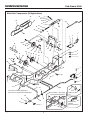
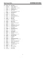
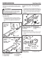
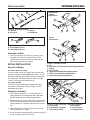
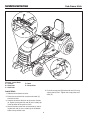
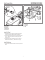
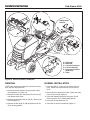
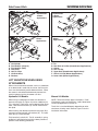
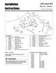
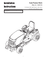
Sub-Frame Hitch
Installation
Instructions
Mfg. No. 1695195
For Prestige / 1800 / 2800, Conquest / 1700 / 2700, &
Broadmoor / 1600 / 2600 Series Tractors
This kit is required when installing front mounted
snowthrowers.
1
Installation Instructions
Sub-Frame Hitch
Main Hitch Components (All Applications)
28
29
27
30
29
25
41
33
39
38
40
37
36
35
42
1
3
32
28
27
32
43
33
25
33
25
33
29
25
25
28
28
2
27
27
26
25
50
27
34
30
4
28
28
27
5
31
22
46
6
25
45
49
22
24
7
48
8
23
9
15
9
9
47
17
16
10
13
18
21
Front Hole for Dozer Applications
Rear Hole for Snowthrower Applications
Front Pulley - Two-Stage
Snowthrower Application
14
11
13
29
44
12
51
26
25
Figure 1. Contents
2
19
Early Manual
Lift Only
(See Instructions)
11
9
27
Hydraulic 20
Lift
28
Installation Instructions
Sub-Frame Hitch
Ref
1
2
3
4
5
6
7
8
9
10
11
12
13
14
15
16
17
18
19
20
21
22
23
24
25
26
27
28
29
30
31
32
33
34
35
36
37
38
39
40
41
42
42
43
44
45
46
47
48
49
50
Part No. Qty.
1723292A 1
1653768A 1
1931335
4
1919381
4
1917356
3
1917372
4
105249
1
1724025
1
2176012
4
1722946
1
8031007
2
171011
1
1928721
2
1723115
1
1733812
2
1733309
1
1733779A 1
1722819
1
1723795
1
1960033
1
1722469
1
1667812
2
1960244
1
1921971
1
1924940
8
162115
1
1916965
7
1916950
6
171247
1
1666287
1
1666294
1
1923701
2
158227
4
1920415
1
1722963
1
1930651
1
1704743
1
1668282
1
1722972
1
1960268
1
1704741
1
1703371
1
1703372
1
1701600
2
1922130
1
1733814A 1
1960074
2
1921210
4
1928352
4
1724387
1
1677135A 1
Description
SHAFT & HOOK ASSY
CLAMP, Support
CARRIAGE BOLT, 5/16-18 x 1
WASHER, 11/32
LOCKWASHER, 5/16
NUT, 5/16-18
PIN, Round Head, 3/8 x 2-3/8
LIFT LEVER ASSY.
SAFETY CLIP
LIFT ROD
SET COLLAR
SPRING, Compression
SET SCREW, 5/16-18 x 1/2
ROD GUIDE
ROD, Latch
ROD, Hitch
HITCH ASSY.
PIN, Headless, 1/2 x 2
BAR, Lift Link
HAIR PIN CLIP
PLATE, Lock, Hydraulic Lift
SPACER
SCREW, Whiz, 3/8-16 x 2-3/4
CAPSCREW, 3/8-16 x 3/4
WASHER PLAIN, 3/8
BELT GUIDE
LOCKWASHER, 3/8
NUT HEX FULL, 3/8-16
PULLEY-FLAT
PULLEY ASS'Y
SPACER-BRG
CAPSCREW, 3/8-16 x 2
SPACER
CAPSCREW, 3/8-16 x 1-1/4
PIVOT BRACKET
NUT LOCK, 3/8-16
TRUNNION
SPRING
GUIDE ASS'Y -SPRING
CARRIAGE BOLT, 3/8-16 x 1-1/4
ROD ASS'Y
V-BELT, Single-Stage Blower
V-BELT, Two-Stage Blower
REFLECTOR
CAPSCREW, 3/8-16 x 2-1/4
PUSH BAR LATCH
CLIP
BOLT, .38-16 x 1
NUT- FLG, .38-16
PULLY-FLAT
BELT GUIDE
3
Installation Instructions
Sub-Frame Hitch
NOTE: Please read through these instructions and the
instructions of any other attachments before beginning
installation.
Change Pulley & Belt - Two-Stage Blower
Only
1. If using this hitch with a two-stage snowthrower, the
front idler pulley must be switched from the right hand
side of the hitch bracket, to the left, and an additional
3/8 x 1 x 1/2 spacer (B, Figure 3) and 3/8-16 x 2-1/4
capscrew (A) is required. Also install the 1703372
drive belt.
WARNING
Before beginning any service work turn off the
PTO, set the parking brake, turn off the ignition,
and disconnect the spark plug wire(s).
INITIAL ASSEMBLY
A
Assemble Hitch
1. Attach the support clamp (C, Figure 2) and hook
assembly (B) to the hitch. Secure with four 5/16-18 x
1 carriage bolts (A), washers (D), lockwashers (E),
and nuts (F). Do not tighten the hardware at this
time.
B
F
E
F
Broadmoor /
1600 / 2600
Series
B
C
D
C
E
Figure 3. Front Pulley - Two-Stage Applications
A. Capscrew, 3/8-16 x 2-1/4
D. Washers, 3/8
B. Spacer, 3/8 x 1 x 1/2
E. Lockwasher & Nut
C. Belt Guide
F. Pulley
D
Assemble Push Bar Latch
1. Attach Push Bar Latch (B, Figure 4), to hitch. Secure
with four .31-16 x 1 bolts (A), and four .38-16 flange
nuts (C).
A
B
B
Conquest / 1700 /
2700 &
Prestige / 1800 /
2800 Series
C
A
C
Four Wheel
Drive Models
D
E
Two Wheel
Drive Models
A
Figure 4. Assemble Push Bar Latch
A. Bolt, .38-16 x 1
C. Flange Nut, .38-16
B. Push Bar Latch
F
Figure 2. Install Support Clamp
A. 5/16-18 x 1 Carriage Bolt
D. 11/32 Washer
B. Hook Assembly
E. 5/16 Lockwasher
C. Support Clamp
F. 5/16-18 Nut
4
Installation Instructions
Sub-Frame Hitch
Snowthrower
& Dozer
Applications
A
C
B
E
D
A
B
Figure 5. Assemble Lift Rod
A. Lift Rod
C. Spring
B. Set Collar
D. Rod Guide
A
C
B
B
D
Mower
Applications
G
Figure 6. Early/Later Lift Links
A. Early Model Lift Link
B. Later Model Lift Link
A
Assemble Lift Rod
1. Install the set collars (B, Figure 4), spring (C), and
rod guide (D) on the lift rod (A) as shown. Final
adjustment of the set collars will be made after the
hitch and attachment are installed.
INITIAL INSTALLATION
Manual Lift Models
LIFT LINK - EARLY VS. LATER
The early model lift link (A, Figure 6) was used on early
production Conquest/1700/2700 Series tractors. It must
be replaced with the later model lift link (B) included with
this attachment. The later model link works in all applications. Discard the early model link (A).
F
C
D
Figure 7. Connect Lift Link
A. Pin
B. Rear Hole of Lift Bar (Snowthrower Applications)
C. Spacer
D. Hair Pin Clip
E. Upper Hole (Snowthrower Applications)
F. Slot of Lift Link (Mower Applications)
G. Lower Hole (Mower Applications)
LIFT LINK POSITION
The lift link is installed differently depending on what
attachment is being used. Refer to Figure 7 for link
installation information.
Hydraulic Lift Models
1. Fully lower the hydraulic lift. The lift assembly is
spring loaded so it will need to be held in the down
position to perform of the following procedures.
2. Remove and retain the flat head pin (B, Figure 8) and
hair pin clip (E) securing the lift cylinder (A) to the lift
shaft assembly (F). Remove and retain the flat washers.
3. Mount the lock plate (D) next to the cams on the lift
shaft assembly (F) as shown.
4. Install the original flat head pin (B) and new flat head 5
pin (C) and secure with hair pin clips.
A
B
F
C
D
E
Figure 8. Install Lock Plate - Hydraulic Lift Models
A. Lift Cylinder
D. Lock Plate
B. Flat Head Pin (Original)
E. Hair Pin Clips
C. Flat Head Pin (New)
F. Lift Shaft Assy.
Installation Instructions
Sub-Frame Hitch
A
B
C
D
E
Figure 9. Install Hitch
A. J-Hooks
B. Hitch Rod
C. Hitch Rod
D. Hook
E. Clamp Plate
Install Hitch
5. Push the clamp plate (D) backwards until it is snug
against the lift shaft. Tighten the clamp plate hardware (E).
1. Slide the hitch under the tractor.
2. Raise the rear of the hitch and place the hook (C)
over the lift shaft.
3. Connect the front of the hitch to the tractor J-hooks
(A, Figure 9) using the hitch rod (B) and a safety clip
in the top holes of the push bar latch.
4. Secure the front of the hitch to the tractor by attaching the hitch rod (C) and a safety clip in the bottom
holes of the push bar latch.
6
Installation Instructions
Sub-Frame Hitch
D
A
B
C
A
C
B
Figure 11. Install Lift Rod - All Models
A. Lift Lever
B. Lift Rod
C. Clip
Figure 10. Install Lift Lever
A. Lift Lever
B. Lift Shaft
C. Safety Clip
D. Clevis Pin
Install Lift Rod
1. Slide the lift lever (A, Figure 10) onto the end of the
tractor lift shaft (B) under the right side footrest.
2. Use the tabs on the lift lever (A) to capture the tractor
lift arm. Secure in place with a clevis pin (D) and
safety clip (C).
3. Insert the rear of the lift rod (B, Figure 11) into the
bottom of the lift lever (A). Secure with a clip (C).
Install Reflectors
1. Install the two reflectors on the rear of the tractor seat
deck.
7
Installation Instructions
Sub-Frame Hitch
Snowthrower
Position
C
D
A
B
E
F
A. Hitch Rod
B. Hitch Rod
C. Lift Lever Extension
D. Lift Link (Manual)
E. Pressure Lock Plate
(Hydraulic)
F. Hook
Figure 12. Normal Installation & Removal
REMOVAL
NORMAL INSTALLATION
NOTE: After removing components, reinstall the clevis
pins and clips to prevent loss.
1. Insert the hook (F, Figure 12) into the back of the
hitch. Mount the rear of the hitch on the lift crossshaft.
1. Disconnect the lift rod from the attachment and lift
lever extension (C, Figure 12).
2. Remove the clevis pin and clip from the lift lever (C)
and remove the lift lever.
3. Remove the front hitch rod (A) and (B). Remove the
hitch and hook (F).
4. Remove the lock plate (E) OR reposition the lift link
(D) in mowing position.
2. Secure the front of the hitch to the J-hooks using the
hitch rod (A) and (B) (Figure 9).
3. Install the downward pressure lock plate (E) OR
place the lift link (D) in snowthrower position.
4. Install the lift lever extension (C).
5. Install the lift rod and attachment (Figure 11).
Installation Instructions
Sub-Frame Hitch
Snowthrower
& Dozer
Applications
Snowthrower
& Dozer
Applications
E
A
A
B
F
C
D
E
C
B
D
Mower
Applications
Mower
Applications
G
A
A
B
F
G
F
E
Figure 13. Lift Lock Plate - Hydraulic Lift Models
A. Lift Cylinder
B. Flat Head Pin (Original)
C. Flat Head Pin (New)
D. Lock Plate
E. Hair Pin Clips
F. Lift Shaft Assy.
G. Washers
C
D
Figure 14. Lift Link - Manual Lift Models
A. Pin
B. Rear Hole of Lift Bar (Snowthrower Applications)
C. Spacer
D. Hair Pin Clip
E. Upper Hole (Snowthrower Applications)
F. Slot of Lift Link (Mower Applications)
G. Lower Hole (Mower Applications)
LIFT VARIATIONS WHEN USING
ATTACHMENTS
When a front-mounted attachment such as a snowthrower or dozer blade is used with the tractor, the lift mechanism must be locked to provide downward force. When
the mower is reinstalled the downward pressure lock
must be released so that the mower can float.
Hydraulic Lift Models
Manual Lift Models
When using a snowthrower or dozer, the downward
pressure lock plate (D, Figure 13) and an additional pin
(C) is installed. These parts are included with the attachment. Note that the washers (G) are not used with the
lock plate.
NOTE: These instructions apply to Conquest / 1700 /
2700 Series tractors or Broadmoor / 1600 / 2600 Series
tractors equipped with a lift lever kit.
The lift link is installed differently depending on what
attachment is being used. Refer to Figure 14 for link
installation information.
When mowing, the downward pressure lock plate (D) is
removed and replaced with two washers (G). The additional pin (C) is also removed.
Fully lower the hydraulic lift. The lift assembly is spring
loaded so it will need to be held in the down position to
perform of the following procedures.
9
Installation Instructions
Sub-Frame Hitch
NOTES
MANUFACTURING, INC.
500 N Spring Street / PO Box 997
Port Washington, WI 53074-0997 USA
Form No. 1734116
Rev. 10/2006
© 2006 Briggs & Stratton, Inc. All Rights Reserved
TP 200-4417-00-AT-SMAN