1
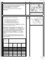
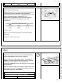
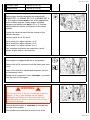
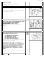
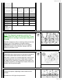
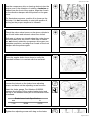
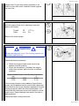
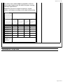
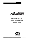
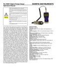
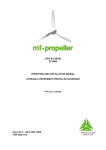
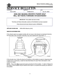
9/04/09 10:11 AM
Overhead Set
(003-004)
Measure
General Information
All overhead lash measurements must be made when
the engine is cold. Stabilized coolant temperature
must be at 60°C [140°F] or below.
Remove the rocker lever cover.
Make sure the engine base timing is properly set
before attempting to measure, adjust, or set the
overhead.
Early engine vibration dampers are marked with
BRAKE SET 1-6, BRAKE SET 2-5, or BRAKE SET 34. The engine brakes must be set at the appropriate
mark on these engines. Newer engine vibration
dampers are marked with only A, B, or C, and are
adjusted with the valves and injector on the same
cylinder.
Locate the valve set marks on the outside of the
vibration damper.
Page 1 of 14
9/04/09 10:11 AM
The set marks are A, B, and C:
Set to mark A to adjust cylinder 1 or 6.
Set to mark B to adjust cylinder 2 or 5.
Set to mark C to adjust cylinder 3 or 4.
Two complete revolutions are required to set all
valves, engine brakes, and injectors.
If the engine is equipped with an air compressor:
Remove the oil fill connector from the lower gear case
cover.
Insert a 3/4-inch drive ratchet and extension into the
air compressor drive.
Rotate the air compressor drive clockwise, as viewed
from the front of the engine.
WARNING
Do not pull or pry on the fan to manually rotate the
engine. To do so can damage the fan blades.
Damaged fan blades can cause premature fan
failures which can result in serious personal injury
or property damage.
The crankshaft rotation is clockwise, as viewed from
the front of the engine.
The cylinders are numbered from the front of the
engine (1-2-3-4-5-6).
The engine firing order is 1-5-3-6-2-4.
If the engine is not equipped with an air compressor:
Loosen the cover plate capscrews and rotate the
cover or remove the oil fill tube, if equipped.
Page 2 of 14
9/04/09 10:11 AM
Use a 1½ inch socket to push the barring gear into the
gear mesh and rotate the barring adapter
counterclockwise to bar the engine.
Rock the barring device back and forth until it
disengages.
Each cylinder has four rocker levers:
The exhaust valve rocker lever (1)
The injector rocker lever (2)
The intake valve rocker lever (3)
The engine brake rocker lever (4).
The intake valve rocker lever is always the long lever
on the valve rocker lever shaft.
Early engine vibration dampers are marked with
BRAKE SET 1-6, BRAKE SET 2-5, or BRAKE SET 34. The engine brakes must be set at the appropriate
mark on these engines. Newer engine vibration
dampers are marked with only A, B, or C, and are
adjusted with the valves and injector on the same
cylinder.
The valves, brakes, and the injectors on the same
cylinder are adjusted at the same index mark on the
vibration damper.
Injector
and Valve
Adjustment
Sequence
Bar Engine
Set
Set
Set
in Pulley
Cylinder Cylinder Cylinder
Direction Position
Injector Valve
Brake
of Rotation
Start
A
1
1
1
Advance to
B
5
5
5
Advance to
C
3
3
3
Advance to
A
6
6
6
Advance to
B
2
2
2
Advance to
C
4
4
4
Page 3 of 14
9/04/09 10:11 AM
Firing
Order: 1-53-6-2-4
NOTE: For illustrative purposes, position A is
shown as the first step. It is not necessary to start
with position A, as long as the proper sequence is
followed.
Use the compressor drive or barring device to bar the
engine over in the direction of engine rotation,
clockwise as viewed from the front of the engine.
Align the A mark on the vibration damper with the
pointer on the gear cover.
Check the valve rocker levers on the given cylinder to
see if both intake and exhaust valves are closed.
Both sets of valves are closed when the rocker levers
and the brake lever are loose. If both sets of valves
are not closed, rotate the compressor drive gear one
complete revolution, and align the A mark on the front
damper with the pointer again.
Valve Lash
Use feeler gauges to measure the amount of
clearance (lash) between the crosshead and the
rocker lever nose. Measure and record the intake,
exhaust, and brake valve lash. If the valve lash is not
within the specifications listed below, the valve must
be adjusted. See the adjust step in this procedure.
Press the brake lever down to verify the camshaft
follower is in contact with the camshaft prior to
measurement of the brake lash.
ISX, QSX Series Valve Lash Recheck Limits
Intake
0.23 mm
minimum
0.006 in
Intake
0.48 mm
maximum
0.019 in
Exhaust
0.56 mm
minimum
0.022 in
Exhaust
0.81 mm
maximum
0.032 in
Brake
6.87 mm
minimum
0.271 in
Page 4 of 14
9/04/09 10:11 AM
Brake
7.13 mm
maximum
0.281 in
Brake Running Clearance
Rotate the brake lever to the detent (neutral) position.
Check the clearance between the engine brake
actuator piston and the cross head guide pin (1). If the
brake running clearance is not within the
specifications listed below, the running clearance
must be adjusted. See the Adjust step in this
procedure.
Brake Running Clearance
mm
0.635
2.79
MIN
MAX
in
0.025
0.110
Injector Lash
There is no service procedure to check the injector
free load.
Install the rocker lever cover.
Adjust
Read the entire procedure for overhead adjustment
before attempting to perform this operation.
Valves, injectors, and engine brakes (if equipped)
must be correctly adjusted for the engine to operate
efficiently. Valve, injector, and engine brake
adjustment must be performed using the values listed
in this section.
After an engine rebuild or any major repair where the
injector and valve setting must be disturbed, set all of
the valves, injectors, and brakes.
Valve, Brake, and Injector Adjustment Values
Injector Adjustment is 8 N•m [70 in-lb]
Intake Valve
0.35 mm [0.014 in]
Page 5 of 14
9/04/09 10:11 AM
Exhaust Valve
0.68 mm [0.027 in]
Engine Brake
7.00 mm [0.276 in]
Early engine vibration dampers are marked with
BRAKE SET 1-6, BRAKE SET 2-5, or BRAKE SET 34. The engine brakes must be set at the appropriate
mark on these engines. Newer engine vibration
dampers are marked with only A, B, or C, and are
adjusted with the valves and injector on the same
cylinder.
Locate the valve set marks on the outside of the
vibration damper.
The set marks are A, B, and C:
Set to mark A to adjust cylinder 1 or 6.
Set to mark B to adjust cylinder 2 or 5.
Set to mark C to adjust cylinder 3 or 4.
Two complete revolutions are required to set all
valves, engine brakes, and injectors.
If the engine is equipped with an air compressor:
Remove the oil fill connector from the lower gear case
cover.
Insert a 3/4-inch drive ratchet and extension into the
air compressor drive.
Rotate the air compressor drive clockwise, as viewed
from the front of the engine.
WARNING
Do not pull or pry on the fan to manually rotate the
engine. To do so can damage the fan blades.
Damaged fan blades can cause premature fan
failures which can result in serious personal injury
or property damage.
The crankshaft rotation is clockwise as viewed from
the front of the engine.
The cylinders are numbered from the front of the
Page 6 of 14
9/04/09 10:11 AM
engine (1-2-3-4-5-6).
The engine firing order is 1-5-3-6-2-4.
If the engine is not equipped with an air compressor:
Loosen the capscrews and rotate the cover or remove
the oil fill tube, if equipped.
Use a 1½ inch socket to push the barring gear into the
gear mesh and rotate the barring adapter
counterclockwise to bar the engine.
Rock the barring device back and forth until it
disengages.
Each cylinder has four rocker levers:
The exhaust valve rocker lever (1)
The injector rocker lever (2)
The intake valve rocker lever (3)
The engine brake rocker lever (4).
The intake valve rocker lever is always the long lever
on the valve rocker lever shaft.
Early engine vibration dampers are marked with
BRAKE SET 1-6, BRAKE SET 2-5, or BRAKE SET 34. The engine brakes must be set at the appropriate
mark on these engines. Newer engine vibration
dampers are marked with only A, B, or C, and are
adjusted with the valves and injector on the same
cylinder.
The valves, brakes, and injectors on the same cylinder
are adjusted at the same index mark on the vibration
damper.
Injector
Page 7 of 14
9/04/09 10:11 AM
and Valve
Adjustment
Sequence
Bar Engine
Set
Set
Set
in Pulley
Cylinder Cylinder Cylinder
Direction Position
Injector Valve
Brake
of Rotation
Start
A
1
1
1
Advance to
B
5
5
5
Advance to
C
3
3
3
Advance to
A
6
6
6
Advance to
B
2
2
2
Advance to
C
4
4
4
Firing
Order: 1-53-6-2-4
NOTE: For illustrative purposes, position A is
shown as the first step. It is not necessary to start
with position A, as long as the proper sequence is
followed.
Use the compressor drive or barring device to bar the
engine over in the direction of engine rotation,
clockwise as viewed from the front of the engine.
Align the A mark on the vibration damper with the
pointer on the gear cover.
Check the valve rocker levers on the given cylinder to
see if both intake and exhaust valves are closed.
Both sets of valves are closed when the rocker levers
and the brake lever are loose. If both sets of valves
are not closed, rotate the compressor drive gear one
complete revolution, and align the A mark on the front
damper with the pointer again.
Loosen the injector adjusting screw locknut on the
cylinder.
Do not use a click-type torque wrench.
Page 8 of 14
9/04/09 10:11 AM
Use a dial-type torque wrench with a range of 0 to 150
in-lb to tighten the injector rocker lever adjusting
screw. If the screw chatters during setting, repair the
screw and lever as required.
Back out the adjusting screw one or two turns.
Hold the torque wrench in a position that allows you to
look in a direct line at the dial. This is to make sure
the dial will be read accurately.
Make sure the parts are aligned, and squeeze the oil
out of the valve and injector train by tightening the
adjusting screw.
Use this initial adjustment to preload the valve train
and injector.
Tighten the injector lever adjusting screw.
Torque
Value:
8 n.m
[71 in-lb
]
Back the adjusting lever screw out 1 or 2 turns.
Tighten the injector lever adjusting screw.
Torque
Value:
8 n.m
[71 in-lb
]
Hold the injector lever adjusting screw and tighten the
adjusting screw locknut.
Torque
Value:
75 n.m
[55 ft-lb
]
After setting the injector on a cylinder, set the valves
and engine brakes on the same cylinder.
Early engine vibration dampers are marked with
BRAKE SET 1-6, BRAKE SET 2-5, or BRAKE SET 34. The engine brakes must be set at the appropriate
mark on these engines. Newer engine vibration
Page 9 of 14
9/04/09 10:11 AM
dampers are marked with only A, B, or C, and are
adjusted with the valve and injector on the same
cylinder.
With the set mark aligned with the pointer on the gear
cover and both sets of valves closed on the cylinder,
loosen the locknuts on the intake and exhaust valve
adjusting screws.
Back out the adjusting screws one or two turns.
Select a feeler gauge for the correct valve lash
specification.
Intake
Exhaust
Valve Lash Specification
mm
0.36
NOM
0.69
NOM
in
0.014
0.027
Insert the feeler gauge between the top of the
crosshead and the rocker lever nose pad.
Make sure the feeler gauge is completely under the
pivoting rocker lever nose pad.
Tighten the adjusting screw.
Torque
Value:
0.6 n.m
[5 in-lb
]
Page 10 of 14
9/04/09 10:11 AM
Use a torque wrench and crows foot adapter to tighten
the locknut.
Hold the adjusting screw in this position. The adjusting
screw must not turn when the locknut is tightened.
Torque
Value:
45 n.m
[33 ft-lb
]
After tightening the locknut to the correct torque value,
remove the feeler gauge.
CAUTION
To get maximum brake operating efficiency and to
prevent engine damage, the brake adjustment
instructions must be followed.
For older engines, locate the engine brake set marks
on the outside of the vibration damper.
The set marks are BRAKE SET 1-6, and BRAKE SET
2-5, and BRAKE SET 3-4.
BRAKE SET 1-6: Cylinder 1 or 6 adjust
BRAKE SET 2-5: Cylinder 2 or 5 adjust
BRAKE SET 3-4: Cylinder 3 or 4 adjust
Page 11 of 14
9/04/09 10:11 AM
Use the compressor drive or barring device to bar the
engine over in the direction of rotation, clockwise as
viewed from the front of the engine. Align the A mark
on the vibration damper with the pointer on the gear
cover.
For illustrative purposes, position A is shown as the
first step. It is not necessary to start with position A,
as long as the proper sequence is followed.
Check the valve rocker levers on the given cylinder to
see if both intake and exhaust valves are closed.
Both sets of valves are closed when the rocker levers
and the brake lever are loose. If both sets of valves
are not closed, rotate the compressor drive gear one
complete revolution, and align the A mark on the front
damper with the pointer again.
Press the engine brake lever down to verify the
camshaft follower is in contact with the camshaft.
Loosen the locknut on the brake lever adjusting
screw, and back out the adjusting screw one turn.
Insert the feeler gauge, Part Number 3163530,
between the bottom of the engine brake piston and
the top of the exhaust valve pin on the exhaust valve
crosshead.
Brake Lever Lash Specification
mm
in
7.00
NOM
0.276
Tighten the adjusting screw until drag on the feeler
Page 12 of 14
9/04/09 10:11 AM
gauge is felt. Proper drag means that there is no
motion of the brake lever camshaft follower against
the cam lobe.
Hold the engine brake lever adjusting screw and
tighten the locknut.
Torque
Value:
20 n.m
[177 inlb ]
Remove the feeler gauge.
CAUTION
Engine damage can occur if the running clearance is
not within specifications.
Check the running clearance:
0. Rotate the engine brake rocker lever to the
detente (neutral) position.
1. Check the clearance (1) between the engine
brake lever actuator piston and the crosshead
guide pin.
Engine Brake Rocker Lever Running Clearance
mm
in
0.635
MIN
0.025
2.790
MAX
0.110
If the running clearance does not meet specification,
loosen, but do not remove the rocker shaft capscrews,
and rotate the shaft in the direction required to bring the
running clearance within the listed specification. It is
critical that this clearance be set and verified on all six
brake levers. Engine damage can result if this task is
not completed.
Check the brake running clearance.
Page 13 of 14
9/04/09 10:11 AM
The rocker lever shafts must be adjusted so that all
three engine brake levers fall within the given running
clearance specification.
Repeat the process to adjust all injectors, engine
brakes, and valves according to the chart shown below.
Injector
and Valve
Adjustment
Sequence
Bar Engine
Set
Set
Set
in Pulley
Cylinder Cylinder Cylinder
Direction Position
Injector Valve
Brake
of Rotation
Start
A
1
1
1
Advance to
B
5
5
5
Advance to
C
3
3
3
Advance to
A
6
6
6
Advance to
B
2
2
2
Advance to
C
4
4
4
Firing
Order: 1-53-6-2-4
Last Modified: 28-Apr-2008
Page 14 of 14