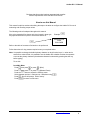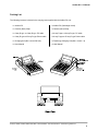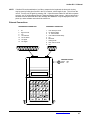
1
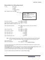
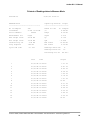
AUDITOR DC I / II
DATA COLLECTOR
Operations Manual
PO Box 16460, Portland OR 97292-0460 • 503-254-6600 • Fax 503-255-2615 • www.aimco-global.com
Auditor DC I / II Manual
Table of Contents
Page No
CE Marking
3
How to use this Manual
3
Packing List
4
Care & Storage
5
Battery Charging
5
Edit Transducer File
6
Barcode Read Input
8
Measure Mode (Up to 200 readings stored)
9
Measure Mode - circle store option
10
Direct measure Mode
11
To Display Recorded data
13
To View Cp and Cpk
13
French Cp and Cpk
14
To Erase Stored Data and Set-ups
To Erase readings stored in measure mode
15
15
Printing
To print readings taken in measure mode
16
16
To set Date and time
17
To Set power off and Backlight Time Delays
17
To Configure Printer Port
17
To Display Software Version Number
17
To set Password Protection
18
To clear Password Protection
18
To Perform Software Reset
20
To Communicate With a PC
21
Example printouts
Printout of Readings taken in measure mode
22
22
Glossary of Terms
23
Error Messages
25
External Connectors
27
CE Marking
PO Box 16460, Portland OR 97292-0460 • 503-254-6600 • Fax 503-255-2615 • www.aimco-global.com
2
Auditor DC I / II Manual
Declares that this product has been assessed and complies
with the requirements of the relevant CE Directives.
How to use this Manual
This manual is split into sections describing the steps to be taken to configure the Auditor DC for use in
measuring and recording torque values.
The following method is adopted throughout this manual.
Keys to be pressed will be shown as the key legend in large type
Any special instructions or point to note will be shown as
Example
INSTRUCTION
TO BE
FOLLOWED
Refer to the table of contents to find action to be performed.
Follow instructions for key presses required to carry out required action.
Note: It is possible to change the default primary character on dual function keys. I.e. when text is
entered into various fields, it is possible to set the Auditor DC to default to either the numerals
or text as the primary character (the alternate character is selected by pressing the shift key
before typing).
To set this:
from Main Menu
Press then press or press (Misc’)
Press then press or press (Software Reset)
Press the 7 times to access the Shift key menu
Select between options 1 Characters or 2 Numbers using Press Screen will prompt; 'End of set-up'
Press to return to main menu
PO Box 16460, Portland OR 97292-0460 • 503-254-6600 • Fax 503-255-2615 • www.aimco-global.com
3
Auditor DC I / II Manual
Packing List
The following items are included in the carrying case supplied with the Auditor DC unit.
1 x Auditor DC
1 x Auditor DC (fastcharge model)
1 x Camera (Neck) Strap
1 x Camera (Neck) Strap
1 x 9 way D type to 9 way D type PC cable
1 x 9 way D type to 9 way D type PC cable
1 x 9 way D type to 25 way D type Printer cable
1 x 9 way D type to 25 way D type Printer cable
1 x Charging Unit (Max. current 500 mA)
1 x Fastcharge Charging Unit (Max. current 1 A)
1 x User Manual
1 x User Manual
PO Box 16460, Portland OR 97292-0460 • 503-254-6600 • Fax 503-255-2615 • www.aimco-global.com
4
Auditor DC I / II Manual
Care & Storage
When not in use the unit should be returned to the supplied carry case.
This unit is designed for indoor use only
Operating temperature range
5-40 degrees C
Storage temperature range
0-50 degrees C
The membrane keypad may be wiped clean with a soft damp cloth. The unit is not waterproofed and spillages
should be avoided.
THIS UNIT CONTAINS NO USER SERVICEABLE PARTS. ONLY QUALIFIED SERVICE PERSONNEL
SHOULD REPLACE OR FIT PARTS.
Battery Charging
The batteries in the Auditor DC unit are shipped fully charged.
In continuous use with a transducer connected the batteries have a life of at least 8 hours.
To charge the batteries following a period of use. Connect the supplied charger to the charging socket on the
right hand side of the unit. Plug in the charger to a suitable supply and switch on. The LED indicator above the
charging socket will light (Red) to indicate that the unit is being recharged. From fully discharged the unit will
require a charging period of 16-20 hours.
The batteries in the unit comprise a 7 cell NiCad with a capacity of 1.6Ahr.
With the unit switched off from a 10% charge state, the batteries will fully discharge in 25-50 days. To prevent
the loss of all set-up data, the unit has additional battery backup for the internal memory.
Automatic Power Off
To conserve battery life in use, the unit will switch off automatically after a predefined period. Pressing the on
key will restore the unit to the last display prior to powering off.
Optional Fast Charge
Auditor DCs with optional Fast Charge, are supplied with internal NiMH (Nickel Metal Hydride) batteries. These
are environmentally friendly batteries presenting no problems for safe disposal and are capable of sustaining a
rapid recharge. From fully discharged the unit will require a charging period of only 2.5 hours approx. Auditor
DC model having this feature are identified by the additional green LED next to the existing LED above the
mains adapter socket.
When the mains adapter is plugged into the socket and switched on at the mains, the green LED will come on to
indicate the machine is charging and will start to flash when the unit is fully charged. If the red LED comes on,
this means there is a problem and usually indicates a faulty battery.
The Fast Charge option also gives an increase in the effective life of the charged batteries.
NOTE:
The mains adapter for the Fast Charge model terminates in a slightly larger diameter plug. This
prevents the use of a standard mains adapter for charging the fast charge batteries. No attempt should
be made to recharge the NiMH batteries using the standard mains adapter - failure to heed this
warning could result in damage to the unit. The fast charge adapter can, however, be used to charge a
standard Auditor DC.
PO Box 16460, Portland OR 97292-0460 • 503-254-6600 • Fax 503-255-2615 • www.aimco-global.com
5
Auditor DC I / II Manual
Edit Transducer File
The following section deals with the editing of transducer files
This section can be skipped if using Auditor Smart type Transducers.
If using any other types of transducer then the following instructions for 'Edit Transducer File' must be
followed before any reading or measurements can be taken.
All Auditor Smart type transducers have in-built circuitry which allow the Auditor DC
to identify the range of the transducer and calibrate the readings automatically. No set-up is
necessary for these types of transducer.
There are 5 other types of transducer which the Auditor DC will accept.
1.
High Output: (H/O) these transducers have an internal amplifier and give an output signal
level of 1-2 Volts.
2.
Industry Standard (IS): These transducers have no internal amplifier. The exact span or rated
torque will be marked on the transducer nameplate. The sensitivity of these transducers is 2 mV/V.,
they are fitted with a 350 Ohm bridge.
3.
Serial: These are digital type transducers and produce an RS232 signal
4.
Keypad (KPD): This is an optional keypad which connects to the Auditor DC.
5.
Keyboard (KEY): Keyboard on Auditor DC
Use of any of the above 5 transducer types requires that settings are made in the transducer file before any
measurements can take place. The procedure for entering settings is given below.
At main menu press
press
Screen will show
(Configure)
(Edit Tx)
Transducer
B (Current set-up)
Complete set-up
The ‘B’ indicates that this is the ‘B’ file in memory. It is the first of 8 memories (labelled B to I) reserved for the
saving of transducer set-ups. Your most used transducer setting should be stored in this memory.
The remaining memories (C to I) may be accessed by pressing .
Press Select transducer type H/O, I/S, SER, KPD or KEY using press Depending on type of transducer selected above continue set-up in the appropriate section overleaf.
PO Box 16460, Portland OR 97292-0460 • 503-254-6600 • Fax 503-255-2615 • www.aimco-global.com
6
Auditor DC I / II Manual
If you have chosen I/S
Select units of measure - inlb, ftlb etc. using type in transducer spantype in mV/V
type in Bridge resistance
type in Pulses Per Rev
type in serial Number
press press press press press (Auditor DC II only)
press To set-up another transducer
press Select another memory (B to I) using the keys and
press to return to the main menu
press If you have chosen SER
select location of decimal point using
press select Baud Rate, Data Bits, Stop Bits and parity in the same manner
to set-up another transducer
press Select another memory (B to I) using the keys and press to return to main menu
press If you have selected H/O
Select units of measure- inlb, ftlb, etc. using Note:
High Output devices usually produce an output voltage of approximately 1-2Volts. This
analogue voltage signal will not be exact and may not be linear. If you are using a device
that has a nominal 1Volt output, we suggest that you multiply the span of your transducer
by 2.5 to determine the new span setting.
Type in your new span
type in Serial Number
screen will indicate ‘End of Set-up’
press press press Connect your high output device and select measure mode
(refer to instruction sheet for measure mode only)
Use an independent measuring device to apply a torque to the transducer and check the reading on the
independent unit against the reading shown on the Auditor DC. It will be necessary to return to the ‘Edit Tx’
menu option and adjust the span setting until the two readings agree. You may have to repeat the above
procedure several times until your high output transducer is correctly calibrated.
PO Box 16460, Portland OR 97292-0460 • 503-254-6600 • Fax 503-255-2615 • www.aimco-global.com
7
Auditor DC I / II Manual
If you have selected KPD
Select location of decimal point using then
Select Parity- Odd, Even or Disabled using then
To set-up another transducer
press press press Select another memory (B to I) using the keys and press To return to main menu
press If you have selected KEY
Select location of decimal point using then
To set-up another transducer
press press Select another memory (B to I) using the keys and press To return to main menu
press Barcode read input for characteristic names and comments.
It is now possible to scan a barcode name in Auditor DC at certain prompt lines. The input of a barcode is
allowed at the characteristic name prompt in store characteristic, direct characteristic and edit characteristic
modes. In addition it is also possible to scan a barcode in the comment field in store characteristic only. Edit
characteristic and normal store behave in a slightly different manner to direct characteristic.
The Auditor DC will accept most bar code reading formats, but not all.
General Operational Method for Scanning bar Code data.
Connect the Bar Code Reader to the Printer/PC connector at the rear of the Auditor DC.
Bar code readings can generally be taken at the prompt to input data (Characteristic name or a comment) when
the flashing cursor is on the screen. This can be on a blank line or following a line of data (an existing
characteristic or a comment). When the cursor is flashing, swipe the code with a bar code reader and observe
the screen. If the flashing cursor disappears, the code has been captured - wait a few seconds for the data to
appear in the display. If the flashing cursor remains, re-scan the code until it is accepted.
When the data is displayed, press to continue. From this point, follow the instructions as for normal data
input.
When entering data via the bar Code reader into a comment field, make sure you have reserved enough
characters in the comment field to accept the code. If the number of characters scanned in exceeds the number
reserved, the Auditor DC will beep and refuse to accept the data. Refer to the instructions on Configuration for
more details.
PO Box 16460, Portland OR 97292-0460 • 503-254-6600 • Fax 503-255-2615 • www.aimco-global.com
8
Auditor DC I / II Manual
Measure Mode (Up to 200 readings stored)
press To start
Press Press (measure)
plug in transducer then press select proper transducer using then press
If using I/S or H/O type transducers
continue with instruct
If using SER, KPD or KEY you are now
ready to take measurements
using
press select peak, track, Impulse or ‘Click Dip’ using
Note: Impulse available on Auditor DC II only
press select measurement direction
using
press
select ‘Cycle end Time’
using
press
select frequency response
using
press select units of measure
(Right is clockwise. Left is anti-clockwise)
type in Max torque value
press type in Min torque value
press type in threshold torque value
press Note:
When selecting a threshold torque value the Auditor DC will ignore any torque which is below
this value. You cannot take another reading until the applied torque falls below this value.
type in amount of Dip
select Second Parameter
using
press press (Auditor DC II only)
If the set-up and transducer has not been changed since the Auditor DC was last used you are now ready to
take torque measurements.
Pressing after taking a series of readings will result in statistical information being displayed (Range, mean
and standard deviation) for the stored readings. To return to measure mode press If you have selected ‘Click Dip’ type in the amount of ‘Dip’ to be sensed press You are now ready to take torque measurements. When finished press PO Box 16460, Portland OR 97292-0460 • 503-254-6600 • Fax 503-255-2615 • www.aimco-global.com
9
Auditor DC I / II Manual
Note:
When taking readings you can change the set-up parameters by pressing the up arrow
Changing any of the set parameters will result in the Auditor DC prompting
to erase all data.
To erase stored readings press
To return to set-up screens press Example: You have been measuring in a right hand direction and you want to switch to
left hand. Press the up arrow twice, change from right hand to left hand. Screen will prompt
to erase all data press to erase all stored readings and return to the measure screen.
Printing of stored readings from measure mode
Pressing from the measure mode will result in all stored readings being printed to an
attached printer.
Note:
Transducer needs to be connected to Auditor DC.
Measure mode circle-store option
Circle-Store is a function to increase the number of stored readings to extend beyond the normal maximum of
200 readings possible in measure mode. With the circle-store option selected, readings will be accepted beyond
the 200 limit but the first readings taken will be lost. Effectively the last 200 readings taken will be stored but the
user is not limited to taking only 200 readings.
To select this option:
From main menu
Press then press
or press (Misc’)
Press then press
or press (Software Reset)
Press the 6 times to access the Circle-store menu
Select option 2 Circle-store On using press Press Screen will prompt; 'End of set-up'
Press to return to main menu
PO Box 16460, Portland OR 97292-0460 • 503-254-6600 • Fax 503-255-2615 • www.aimco-global.com
10
Auditor DC I / II Manual
Direct Measure Mode (Smart Type transducers only)
Direct measure mode is to allow an operator to connect different transducers which may have different spans
and an angle output and can switch between them using an external T switch. This is a display only function and
readings are not stored or printed out.
To start press press press (Direct)
press (Direct Measure)
press (Set-up)
using
press select peak, track, Impulse or ‘Click Dip’ using
Note: Impulse available on Type II only
press select measurement direction
(Right is clockwise. Left is anti-clockwise)
select units of measure
using
press select ‘Cycle end Time’
using
press select frequency response
using
press type in the Threshold Percent. (mx 50.0 mn 0.0) and press
type in amount of Dip (mx 100.0Nm mn 0.0Nm) and press
select Second Parameter
Screen shows; 'End of set-up'
using
press (Auditor DC II only)
press to exit
Press to return to main menu
PO Box 16460, Portland OR 97292-0460 • 503-254-6600 • Fax 503-255-2615 • www.aimco-global.com
11
Auditor DC I / II Manual
The READ option allows you to read the torque from a connected transducer.
From the main menu
press
(Direct)
press
(Direct Measure)
(Read)
press If no transducer is connected, display will prompt; 'Insert Tx' (transducer)
connect transducer and press
Screen will show the span of the connected transducer and the torque measured in units selected at set-up.
The display will show the last reading taken until the next torque input exceeds the threshold level set.
Note: if password protection has been set on Direct measure, then exit is by password only. A correct
password returns you to the set-up read sub-menu. Entering three incorrect passwords will force
the user back into read mode. See password protection later in this book.
PO Box 16460, Portland OR 97292-0460 • 503-254-6600 • Fax 503-255-2615 • www.aimco-global.com
12
Auditor DC I / II Manual
To Display Recorded Data
From main menu press
(Display/Analyse)
Screen will show job name and Specs press
Screen will now show x-bar, R and sigma for total readings
From any Subgroup display press
(down arrow)
Screen will show the Date and Time the readings for that subgroup were taken
Press (down arrow) screen will show subgroup comment.
Press (down arrow) again to see the individual readings displayed in groups of four readings per screen
To View Cp and Cpk
At the job name/spec screen press (down arrow)
screen will show the Cp and Cpk and the number of samples used in the calculations
press (down arrow)
Screen will now show x-bar, R and sigma based on all of the data ( all subgroups calculated together)
The number of samples that were NOK will also be displayed expressed as a percentage.
Press (down arrow)
Screen will show the highest and lowest torque’s recorded and the number of readings that were above the
maximum torque value and minimum torque value.
To return to the main menu press For more information on Cp, Cpk and CAM, please refer to the glossary on page 23.
PO Box 16460, Portland OR 97292-0460 • 503-254-6600 • Fax 503-255-2615 • www.aimco-global.com
13
Auditor DC I / II Manual
French Cp and Cpk
It is possible to view the French Cpk/CAM calculations as an alternative to the standard Cp and Cpk.
Readings must be a minimum of 30 samples.
To set this function:
From main menu
Press then press or press (Misc’)
Press then press or press (Software reset)
Press 5 times to access the Cpk Calculation screen
Use the and arrow keys to access option 2 French Cpk/CAM and press Press to confirm. Screen will prompt; 'End of set-up'
Press to accept and exit or to edit
Press to return to main menu
Returning to Normal Cpk calculations is done as above, selecting option 1 Normal Cpk/no CAM
For more information on Cp, Cpk and CAM, please refer to the glossary on page 23.
PO Box 16460, Portland OR 97292-0460 • 503-254-6600 • Fax 503-255-2615 • www.aimco-global.com
14
Auditor DC I / II Manual
To Erase Stored Data and Set-ups
To Erase readings stored in measure mode
From the main menu press
then press
(Measure)
Screen will prompt 'Erase Measure data?'
press
or press
to erase data
to ignore and continue
PO Box 16460, Portland OR 97292-0460 • 503-254-6600 • Fax 503-255-2615 • www.aimco-global.com
15
Auditor DC I / II Manual
Printing
To print details of set-up or analysis of data
To print readings taken in measure mode
Connect Auditor DC to printer and switch printer on
On Auditor DC
Press Press Press (right arrow) then press
Press
or press (Print))
then press or press (Print Measure)
Auditor DC will print details of stored readings taken in measure mode (with date/time stamp)
A sample printout can be found in Appendix A
To return to main menu press PO Box 16460, Portland OR 97292-0460 • 503-254-6600 • Fax 503-255-2615 • www.aimco-global.com
16
Auditor DC I / II Manual
To set Date and time
From main menu
Press then press
or press (Misc’)
Press (Set Date/Time)
Select date format using Enter date and time and press To return to main menu press
To set Power Off and Backlight Time Delays
From main menu
Press then press
or press (Misc’)
Press (Select Power Off/Backlight Time Delays)
Select Power Off time delay using
press Select Backlight Delay using press To return to main menu press
To Configure Printer Port
From main menu
Press then press
or press (Misc’)
Press then press or press (Printer port)
Select Baud Rate using then press Select number of data bits using then press Select number of Stop Bits using then press Select Parity using then press To return to main menu press To Display Software Version Number
From main menu
Press then press
or press (Misc’)
Press then press
or press (Version #)
To return to main menu press PO Box 16460, Portland OR 97292-0460 • 503-254-6600 • Fax 503-255-2615 • www.aimco-global.com
17
Auditor DC I / II Manual
To set Password Protection
From main menu
Press then press
or press (Misc’)
Press then press
or press (Password)
Screen will prompt; 'Enter new Password'
Type in the password (4 characters) and press Screen will prompt; 'confirm password'
Press to accept or to reject
Select desired option using . Options for protection are:
1.
2.
3.
4.
5.
6.
Power up
Configure
Direct Measure
Direct Char
Software Reset
Date and Time
Press to protect your selected option or
to exit
NOTE: when an option is password protected, # appears in the top right of the display window.
Pressing will remove the protection
Press to exit
Display now reads: 'End of set-up'
To return to main menu press or press to edit password protection.
The remaining options can be password protected in the same manner.
To clear Password Protection
From main menu
Press then press
Press then press
or press (Password)
or press (Misc’)
Screen will prompt; 'Password'
Enter the existing password (4 characters) and press Screen will prompt; 'Confirm Password' and display the existing password
Press to confirm or press
to clear the password protection.
Screen will prompt; 'Enter new Password'
Press to clear the password
(keying in 4 characters before pressing will result in a new password being created)
Screen will say 'Confirm password'
Press to confirm and password is cleared.
PO Box 16460, Portland OR 97292-0460 • 503-254-6600 • Fax 503-255-2615 • www.aimco-global.com
18
Auditor DC I / II Manual
Notes on Password Protection
Be aware of the implications of password protection. Always keep a note of the chosen password
somewhere safe. As there is no function to enable an existing password to be removed without it first
being entered, it may be advisable for the person who is ultimately responsible for the Auditor DC to
initially set a password and issue it only to personnel who need the information. This will prevent an
unknown password being entered, accidentally or deliberately, without anyone else’s knowledge. If
an unknown password is encountered, please contact AIMCO for advice.
PO Box 16460, Portland OR 97292-0460 • 503-254-6600 • Fax 503-255-2615 • www.aimco-global.com
19
Auditor DC I / II Manual
To Perform Software (S/W) Reset
CAUTION:
Use of this function will result in the loss of all stored data. Following this procedure will return
the Auditor DC to its factory default state. This feature should only be used when
it is desired to clear all settings from the Auditor DC.
From main menu
Press then press or press (Misc’)
Press then press or press (S/W Reset)
Press the key 8 times to access the Software Reset screen.
Screen will display 'Erase all data and set mode?'
press To carry out S/W reset
To exit without performing S/W reset press
Screen will display 'ERASING ALL CHARACTERISTICS ROUNDS AND MASTER ROUNDS'
- wait a moment for display to change
Select Subgroup mode using and press screen will say 'End of set-up'
To return to main menu press
There are a number of other parameters which are set from the Software Reset Menu, some of which are
detailed elsewhere in this manual.
Pressing after making a selection will take the user on to the next screen.
Pressing will give the user the option to exit to the Misc menu by pressing or continuing to edit
by pressing .
Screens can be skipped using the and keys.
These are the settings in the order they appear when the Software Reset Menu is accessed.
Cm max samples
-
type in the required figure Cm min samples
Language
Autoprint mode
Capability label
Cpk Calculation
Circle-store (On/Off)
Shift key mode
-
type in the required figure select using select using select using select using select using select using PO Box 16460, Portland OR 97292-0460 • 503-254-6600 • Fax 503-255-2615 • www.aimco-global.com
20
Auditor DC I / II Manual
To Communicate With a PC
(optional software required)
Connect Auditor DC to PC via cable provided
On PC start PCComms Software
On Auditor DC
Press Press Press
then press or press You can now set-up and view all information/data via the PC
NOTE:
This optional PC software is used primarily to write and store characteristics and rounds on
the PC. The format of the data stored on the PC, is of little use to the computer operator
without further processing.
PO Box 16460, Portland OR 97292-0460 • 503-254-6600 • Fax 503-255-2615 • www.aimco-global.com
21
Auditor DC I / II Manual
Printout of Readings taken in Measure Mode
AUDITOR DC
07/01/95 12:39:12
MEASURE-Peak
Capability Results
-----------------------------------
---------------------------
No of Samples
200
Based on last
Transducer
A UTA 75.00 Nm
/x
6.96 Nm
Range
8.30 Nm
Serial Number:
99999
Torque
15. samples
Measurement Dir
Right
Sigma
2.210
Max Torque Value
20.00 Nm
Cp
0.754
Min Torque Value
10.00 Nm
Cpk
Thrshld Torq Val
2.00 Nm
Freq response
Cycle end time
1676 Hz
0.1 Sec
- 0.458
Max found
12.65 Nm
Min found
4.35 Nm
Readings above max
0.
Readings below min
13.
Percentage not OK
Date
Time
86.66 %
Torque
1
07/01/95 12:38:32
7.21 LO
2
07/01/95 12:38:35
4.87 LO
3
07/01/95 12:38:38
6.65 LO
4
07/01/95 12:38:40
6.56 LO
5
07/01/95 12:38:42
7.45 LO
6
07/01/95 12:38:45
5.76 LO
7
07/01/95 12:38:47
7.07 LO
8
07/01/95 12:38:49
9
07/01/95 12:38:52
9.37 LO
10
07/01/95 12:38:54
5.29 LO
11
07/01/95 12:38:56
6.09 LO
12
07/01/95 12:38:59
4.35 LO
13
07/01/95 12:39:01
5.90 LO
14
07/01/95 12:39:04
5.25 LO
15
07/01/95 12:39:06
12.65
10.03
PO Box 16460, Portland OR 97292-0460 • 503-254-6600 • Fax 503-255-2615 • www.aimco-global.com
22
Auditor DC I / II Manual
Glossary of Terms
Characteristic
Specification of one particular torque value to be collected.
Each characteristic has a name of up to 14 characters, 8 if
downloaded from a PC. Auditor DC can store up to 48
different characteristics at any one time.
Cp
This is a capability index which shows the process capability
potential but takes no account of how centred the process is. This
is used for capability studies and Cp may range in value from
0 to infinity. A large value indicates greater potential capability
and a value of 1.33 or greater is desirable.
Cp =
Max - Min
6
(Max and Min are limit values)
CpK
This is an index which indicates whether the process will produce
units within the tolerance limits. If the process is centred on the
nominal value then CpK will have a value equal to Cp. For values
of CpK between 0 and 1 then some of the 6 sigma spread will fall
outside tolerance limits but for values greater then 1 these will all be
within tolerance. A negative value of CpK indicates that the process
mean is outside tolerance limits. A value of 1.33 or greater is desirable.
(Max CpK = lesser of
3
-)
( - - Min)
or
3
(Max and Min are limit values)
CAM
This is an alternative capability index requiring a minimum of 30 readings
to be taken. In this implementation, 5 sub-groups of 6 samples are used
for each calculation. The CAM calculation uses the following formula:
Max - Min x Cam Factor *
6 x Average Sample Value
* CAM Factor is taken from a table (in the case of 5 x 6 samples = 1.910)
High Output
Transducer (H/O)
Torque transducer with no coding links but internal pre-amplifier
giving an output signal level of typically 1 or 2 volts.
Horizontal
sampling
Collection of data by round, taking one reading for each characteristic
in turn.
Industry
Standard
Transducer (I/S)
Type of transducer, with no pre-amplifier or coding links, but with the
exact rated torque, marked on the body.
Master Round
A sequence of up to five rounds. It is used to allow a collection sequence,
which is part vertical, part horizontal.
Max Torque
Upper tolerance level of any reading. This can equal but not exceed the
PO Box 16460, Portland OR 97292-0460 • 503-254-6600 • Fax 503-255-2615 • www.aimco-global.com
23
Auditor DC I / II Manual
Value
torque rating of the transducer to be used.
Min Torque Value
Lower tolerance level of any reading.
No. of Sub
Groups
Number used to allocate memory space in Auditor DC, for a particular
characteristic. May be set in the range of 1 to 99.
Round
Sample
A sequence of characteristics to be collected either horizontally or vertically.
Each round has a name of up to 14 characters, 8 if downloaded from the PC.
Individual torque reading.
Standard
Deviation
Is a measure of the variation of the samples of a statistical group. If a group of
n values has a mean of x- then its standard deviation is given by;
n
=
(xi i=1
n - 1
)
Sub-Group
grouping of samples to enable analysis, with an allowable range of 1 - 50.
Threshold
Torque Value
level of torque, which a signal must rise above and then fall below, to be
considered a valid torque cycle. This may be set in the range of 1 to 50%
of rated span or the Min Torque Value, whichever is the lower.
Units of
Measure
It is possible with Auditor DC to read a transducer calibrated in say Nm
and convert internally to display and store in any of the other torque units.
Vertical
Collection of data by round, where a full sub-group is collected for a
characteristic, before stepping to the next characteristic.
Vertical plus
Prompt
Identical in procedure to that of Vertical mode except that before stepping to the
next characteristic, Auditor DC will prompt for the fitting of a transducer (even
though the correct one is installed) and will require the ENTR key to be pressed.
PO Box 16460, Portland OR 97292-0460 • 503-254-6600 • Fax 503-255-2615 • www.aimco-global.com
24
Auditor DC I / II Manual
Error Messages
Code
Message
Explanation
101
RANGE
The selection made is not within the allowable range.
See the limits specified max to min.
104
EXISTS
The characteristic name entered already exists.
105
NO SPACE
Insufficient memory space is available to create a new
characteristic.
106
NONE
No characteristics have been created.
107
ON PC
Characteristic or round was sent from PC. These may
not be edited or erased on Auditor DC.
108
CONV' OUT
OF RANGE
The units selected would generate too great or too small
a number.
109
NO NAME
A characteristic name must be entered.
110
NO SET-UP
The characteristic exists but configuration is not complete.
111
NO DATA
The characteristic exists, but no data is stored.
113
DAT STR
More than one sub group of data is now stored.
114
ALL STR
All of the sub groups for this characteristic have now been
collected. Erase these after printing to allow further collection.
120
NO Tx
UTA Transducer has been selected but none is connected.
121
TxID - FLT
Transducer ID level not recognised. Use another transducer
or get transducer recalibrated.
122
AZ OFSET
An auto-zero calibration on the transducer has detected an
excessive offset from zero.
123
AZ DISCR
An auto-zero calibration on the transducer has detected an
excessive discrepancy between the Tracking and Peak inputs.
124
Tx FAULT
ADC saturation due to transducer fault, no transducer fitted or
over torque
200
INCOR-TX
The correct UTA transducer is not connected.
300
IN ROUND
This characteristic has already been included in the round.
301
CHARACTS
A minimum of two characteristics must be defined before
entering Edit Round.
PO Box 16460, Portland OR 97292-0460 • 503-254-6600 • Fax 503-255-2615 • www.aimco-global.com
25
Auditor DC I / II Manual
306
RS232
Invalid RS232 data on the serial input.
400
INVALID
Incorrect time or ate format.
600
ONLY 1
Only one round programmed so not possible generate
master round.
601
NO RND
No rounds programmed so not possible to generate
master round.
602
IN M RND
This round has already been entered into the master
round. It is not possible to enter a round twice.
701
RND COMP
The round is complete, no skipping is allowed.
702
ALL SKIP
All other characteristics have already been skipped.
800
MEMORY
Message on power up if memory error found. (See 6.4)
801
MENU ERR
Invalid menu entered due to fault.
802
PROM CKS
The EPROM has an error.
803
OP CODE ERR
The processor has attempted to execute an illegal
instruction.
804
STACK ERR
The processor stack has overflowed.
901
TX SPEC
Illegal transducer specification number received from PC.
902
TX TYPE
Illegal transducer type received from PC.
904
TX UNITS
Illegal transducer units data received from PC.
905
SERIAL
Illegal serial transducer data received from PC.
906
UNITS
Illegal units of measure data received from PC.
907
DIRECT
Illegal direction data received from PC.
908
NAME
Name sent from PC is too long.
909
RANGE
Numeric Parameter sent from PC is out of range.
920
RS232
Error receiving RS232 data from PC.
921
TIMEOUT
Timed out receiving message from PC.
922
CRC
Message received from PC has incorrect CRC value.
923
ILL MSG
Illegal message received from PC.
PO Box 16460, Portland OR 97292-0460 • 503-254-6600 • Fax 503-255-2615 • www.aimco-global.com
26
Auditor DC I / II Manual
NOTE:
If Auditor DC can be switched on, but fails to respond to the keyboard, the electronic circuitry
may be reset by linking pins 5 and 6 in the PC connector, with a length of wire. This will turn the
unit off. Turn the unit on again by pressing ‘ON’. If after this reset Auditor DC still fails to operate
correctly, use '6' for Miscellaneous and '6' Software Reset to clear memory. Having carried out a
hardware reset as described above the message '800 MEMORY' may be displayed on the next
power up, and a software reset should be carried out.
External Connections
TRANSDUCER CONNECTOR
PRINTER/PC CONNECTOR
1
2
3
9
13
14
15
1
2
3
4
5
6
7
8
9
0V
High Level I/P
+5V
-Ve Excitation
+Ve Excitation
-Ve Signal
+Ve Signal
RTS Ready To Send
Rx Receive Data
Tx Transmit Data
DTR Data Terminal Ready
-0V
Not Reset
Analogue O/P
CTS Clear To Send
+5V
CHARGER SOCKET
Centre +12V
Outer
-0V
PO Box 16460, Portland OR 97292-0460 • 503-254-6600 • Fax 503-255-2615 • www.aimco-global.com
27