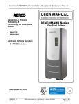
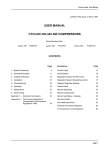
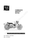
1
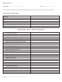
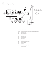
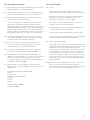
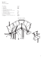
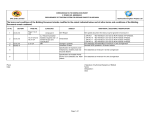
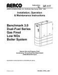
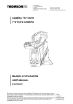
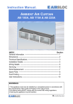
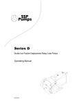
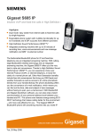
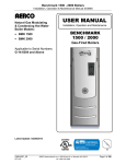
DIRECT GAS FIRED CHV UNIT
DIRECT GAS FIRED CHV UNIT
RM 220 80:20
WITH SMARTCOM
Installation, Commissioning
& Service Manual
Index
Section
1.
Technical Specification
2.
General Description
3.
Shipping List
4.
General Installation - including Roof Opening Diagrams
5.
Connection of Services
6.
Commissioning and Testing
7.
Commissioning Setting
8.
Schematic Diagrams
9.
Operating Instructions
10.
Fault Finding
11.
Servicing
12.
Recommended Spare Parts
13.
Replacement Instruction
Appendix 1 Leak testing the gas line.
Appendix 2 NGII Burner Assembly.
Appendix 3 Wiring Diagram
Appendix 4 Commissioning Sheets
Appendix 5 SmartCom Manual
1.0 Technical Specification
Heater model number
Country
Outside design temperature
Max supply temperature
External resistance
Air volume
Maximum heat input
Minimum heat input
Maximum heat output
Minimum heat output
Gas type
Category
Flue type
Gas rate
Burner pressure high fire
Start gas burner pressure
Profile plate diff pressure
Maxumum fuel gas supply pressure
Minimum fuel gas supply pressure
Fuel gas connection size
Gas port size
Heater arrangement
Profile plate opening full fresh air
Profile plate opening min fresh air
Profile plate opening recirculation air
Burner module
Fan motor rating
Fan pulley
Motor pulley
Belt size
Electrical supply
Power consumption
MCB rating 415 volt
MCB rating 240 Volt
Fuse rating 24 Volt
Weight
RM 220
GB + IE
-2 ºC
40 ºC
30 Pa
4.2m3/sec
220 kW
18.0 kW
198 kW
16.2 kW
Natural gas (G20)
I 2H
A2
21.1m3/hr
6.0mbar Differential
5.0mbar
1.0-2.0mbar
100 mbar
20 mbar
1” BSP
1.8mm DIA
Vertical indoor
912mm x 450mm
912mm x 195mm
912mm x 257mm
18”
4kW
SPZ 200-3
SPZ 90-3
SPZ 1560
415V/3PH/ 50Hz / 4 Wire
4kW
20 AMP MCB
4 AMP MCB
2 AMP MCB
200 Kg
1
2.0 General Description
The unit is fitted with hinged removable access panel doors on
the side of the heater for inspection internally of the fan,
motor, and burner module.
2.1 Introduction
The Nordair/Niche RM air heater is a direct fired unit designed
for economical and efficient operation to give clean, healthy
environmental conditions and constant, even temperature
control.
The heater air fan, motor and drive belts are fitted inside the
heater casing on the downstream side of the burner.
2.4 Control System
The space temperature is controlled via a room sensor, situated
at low level, with the heater discharge air temperature
controlled between two adjustable set points, via a duct sensor
mounted in the discharge head.
a) The heater is available as a full fresh air model, suitable for
make up air applications, or with the patented Nordair/Niche
80/20 recirculation system.
b) Both versions feature a burner mounted in an air handling
unit. The burner is especially designed so that a proportion of
the incoming air is forced into contact with the flame to ensure
rapid mixing and uniform heating to the desired temperature.
Each heater is supplied complete with automatic safety and
temperature control systems.
2.5 Control Sequence
Occupancy times are set within the SmartCom control panel
mounted at low level.
Outside of occupancy times, a frost set point within the
SmartCom unit will start the heater automatically if the room
temperature falls below the frost set point.
c) Full Fresh Heating Air System
A double inlet centrifugal forward curved fan, belt driven from
a TEFV electric drive motors, draws fresh air from outside of the
buiding through a direct gas fired burner situated within a
fixed profile opening, which tempers the air up to the required
temperatures prior to discharging into the building via a
distribution head.
During occupancy times, and below room set point; the heater
operates in full fresh air mode with the discharge air
temperature being controlled at 40ºC (adjustable) via the duct
sensor mounted in the discharge head. It achieves this by
modulating the gas control valve motor via an 0-10v dc control
signal.
Patented 80/20 Recirculation Heating System
The 80/20 system incorporate the main fresh air feature, with
the addition of a moving profile. Dampers allow 80% of the
previously heated air discharged into the building to be
recirculated through the heater, once the building has achieved
room set point, with the remaining 20% being fresh air which
is induced through the burner.
The moving profile dampers, comprise of two horizontal plates
mounted off bearing runners, with a linbage system connected
to a single drive motor. In heating mode, the dampers are
driven to the full fresh air position, which closes off the recirc
air openings, giving a full fresh air opening around the burner.
Once room set point is achieved the profile plates are driven to
the full recirc position, which close the opening around the
burner so that only 20% fresh air is drawn into the heater, with
80% being drawn through the recirc openings.
a) When room temperature set point is achieved, the discharge
air temperature is reset to 25ºC (adjustable), and the profile
plates are driven to the full recirculation position. The heater
will continue to operate in this mode to maintain the room set
point, unless additional heat gains within the space, increase
the room temperature 1ºC (adjustable) above set point, then,
at this point the burner will be switched off, leaving the fan
operating in the 80% recirc, 20% fresh air position.
Additional Increases in space temperature4ºC (adjustable) will
drive the 80/20 dampers to the full fresh air position.
2.6 Control Panel
The heater control panel incorporates the Satronic flame
programmer, necessary contactors, relays and indication
lamps, etc all pre-wired to a terminal rail.
2.2 Gas Burner Assembly
A remote SmartCom panel is supplied with each heater.
The panel should be mounted at low level and wired back to
the heater control panel.
Each burner is built up from modular components to give the
required heat duty. The burner consists of a heavy-duty iron
body which forms the fuel gas manifold, fitted with stainless
steel mixing plates carefully designed to withstand the stresses
of thermal expansion. The mixing plates are perforated to
ensure intimate and progressive mixing of the incoming air
with the fuel gas at all firing rates.
Supplied as loose items for mounting adjacent to the panel is a
room sensor, which must be wired to the SmartCom panel.
The Nordair/Niche SmartCom controller mounted at low level
provides a number of functions which can be adjusted at low
level,including time schedules, temperature setpoints,
heating/ventilation select, holiday periods, overtime extensions,
lockout reset. See Appendix for the SmartCom operating
manual.
Each burner assembly incorporates an integral pilot burner with
spark igniter and flame rod. The flame rod is used for detecting
both the pilot and main flame.
2.3 Heater Casing
The heater casing comprises of an aluminium sheet metal skin
fitted to a aluminium Pentapost frame. The casing incorporates
a burner, galvanised profile plate and mild steel flat bar burner
supports.
2
2.7
Burner Sequence
The purge, ignition, main flame stages of the burner are carried
out via Satronic TMG.740 approved flame programmer.
control panel.
Overheat
In the event of an over-heat condition, within the heater
casing, the heater is fitted with over temperature protection,
which has to be manually reset if activated. Indication is given
by an amber illuminated push button, which has to be pressed
to reset this condition.
The assembly is strapped onto a 1200mm x 1200mm wooden
pallet for easy off loading.
2) 1-off
SmartCom controller
3) 1-off
room sensor.
4) 1-off
PV 75 GRP soaker sheet.
The RM heater includes the following safety interlocks:-
5) 1-off
PV 75 GRP base, square aperture.
1. Low air differential pressure switch.
2. Overheat Controller.
3. Lockout on flame failure/ or air pressure failure.
6) 1-off
PV 75 GRP square cowl.
7) 1-off
correction bend with loose flange for site
assembly.
8) 2-off
main purlin trimmers.
9) 4-off
purlin end cleats.
2.8 Safety Interlocks
2.9 Site Wiring
Site wiring requires the connection of:1. 415 volt 3 phase 50Hz, 4-wire supply, to the main heater
control panel.
2. 9 core PLUS earth cable to the SmartCom panel from
heater.
10) 2-off masking flanges.
11) 1-off set of fixing nuts/bolts washers and rivets.
4.0 General Installation
3. 2 core twisted pair screened from SmartCom panel to room
sensor, if external room sensor is used.
4. 2 core twisted pair screened from SmartCom main heater
control panel.
2.10 Fuel Supply System
Start Gas Supply Line
The start gas line comprises:-
4.1 Related Documents
The installation of the Nordair/Niche Direct Gas Fired Air heater
must be in accordance with the relevant requirements of the
current Gas Safety (Installation and Use) Regulations, Building
Regulations, and the IEE Wiring Regulations.
It should also be in accordance with any relevant requirements
of the local supplier of gas, Local Authority and Fire Authority,
and the relevant recommendations of the following docu
ments:
1. Inlet gas isolating valve.
4.1.1British Standards
2. Gas governor.
BSEN525:1997 -
Requirements for non domestic gas
fired forced convection air heaters for
space heating.
BSEN6230 -
Specification for installation of gas fired
forced convection air heaters for com
mercial and industrial space heating of
rated input exceeding 60kW (2nd family
gases).
3. Class 1 approved solenoid valves.
4. Gas isolating valve.
5. Pipe work, fittings and pressure test points.
The main gas train comprises:1. Inlet gas isolating valve.
4.1.2 Institution of Gas Engineers Publications
2. Combined gas governor, safety shut off valves and strainer.
3. Motorised control ball valve.
4. Burner isolating valve.
5. Pipe work, fittings and pressure test points.
IGE/UP/1
IGE/UP/2
Soundness testing and purging of industrial and
commercial gas installations.
Gas installation pipe work, boosters and
compressors on industrial and commercial
premises.
4.2 Installation of CRM heater
3.0 Shipping List
This shipment comprises
Only a competent person shall be allowed to install a CRM
heater.
1) 1-off fully assembled burner/fan section pre-wired to a
3
The heater is to be installed at a minimum height of 3m and
below a maximum height of 20m from floor level to its base,
manufacturer to be consulted for heights above this. The
heater must be situated to give 500mm access on all sides, with
the discharge nozzle blowing into free area.
The allowable external resistance to the fresh air duct work is
30pa.
Under NO circumstances must the inlet correction bend/duct
work be extended or modified.
The roof openings must be prepared in accordance with the
details in diagrams 1-4, pages 5-8. Please note the opening in
the cladding is larger than that in lining. Nordair/Niche
recommend packing is placed between cladding and lining to
prevent sag around the roof opening.
Once the roof opening has been prepared, apply sealant so that
the final assembly will be absolutely watertight. The soaker
sheets may now be fitted. Nordair/Niche soaker sheets are
designed to fit under the roof ridge cap. With a flat ridge cap,
please ensure all the profile filler is replaced and properly
sealed when the soaker is fitted. With a profile ridge cap,
please ensure sealant is applied to the soaker sheet for a watertight fit with the ridge cap. Use all the available roof fixings to
secure the soaker sheet. Nordair/Niche recommend two
additional fixings in the middle of each side flap. Please note,
where ever possible, you should drill the soaker on a rise in the
profile to minimise the risk of water ingress.
Having fitted the soaker sheet, the roof angle correction bend
may be positioned over the bolts so that the unit will hang
vertically inside the building.
The roof cowl fits over the same bolts and is secured
tightly. The roof cowl can be supplied in the colour of the
room cladding. It is fitted with a turndown base to prevent
water ingress. Some clients may ask for additional water
proofing but in our experience this is not necessary. All remain
ing installation work can now be completed inside the building.
Cut purlin trimmers to size and secure to purlins and correction
bend.
Each RM is supplied with 2 purlin trimmers and fittings.
They are pre-drilled at each end with an adjustable cleat at one
end to compensate for minor deviations in purlin centres. Five
bolts are provided to attach the roof angle correction bend to
each purlin trimmer.
The weight of the unit is now transferred onto the purlins.
The heater burner section may then be fitted to the roof angle
correction bend followed by the fan section bolted to the burn
er section.
It is recommended that guide wire should be fitted through the
eye bolts loacted at each corner of heater to a pre-drilled point
approximately 100mm form the end of the purlin trimmers and
secured by 3 bulldog grips.
4.3
4
The remote SmartCom controller should be mounted 1.5m
from floor level to an adjacent column underneath the heater
which is not subject to high ambient temperatures from local
machinery or air velocity discharging from the heater.
The SmartCom controller incorporates an internal room sensor or
alternatively a remote sensor is supplied for installation away from
the controller.
Sketch No 1
Cowl
4 off steel support
brackets (supplied by
Nordair)
Airflow
915 SQ
Base
Soaker
75x75x100 purlin
cleats
Purlin
150x75 channel
purlin trimmer
50x25 masking angle
Loose flange
5
Sketch No 2
Plan of opening
aker
d so
e
l
i
f
Pro s only
t
shee
ding
Clad
n
latio
Insu
g
Linin
f
Roo
e
g
an l
Roof
purlins
Roof apex
ding
Clad
n
latio
Insu
g
Linin
950 Square hole through
cladding required for flat
soaker sheets
6
Roof profiled soaker
sheets required additional
1220x165 cut out to
accomadate soaker sheet
gulley
Sketch No 3
Detail of PV 75 square cowl
Detail of PV 75 base
Detail of PV 75 flat soaker
7
Sketch No 4
Side view between purlins
5 off M8 bolts
50x50 angle purlin
cleat 4 off M10 bolts
4 off guy wires
Note Purlin trimmers drilled and cut to suit purlins
View between purlins trimmers
50x25 masking angle
150x75 channel
purlin trimmer
8
5.0 Connection of Services
5.1 Gas Supply
The Nordair/Niche heater is designed for use with natural gas
only. The gas type for this heater is marked on the Appliance
Data Badge. Check that the available gas supply is as marked
and within the pressure range given in the heater specification.
5.1.1Service Pipes
The local supplier of gas should be consulted at the installation
planning stage in order to establish the availability of an
adequate supply of gas. An existing service pipe must not be
used without prior consultation with the local supplier of gas.
5.1.2Meters
A gas meter is connected to the service pipe by the local
suplier of gas or the local contractor.
An existing meter should be checked, preferably by the local
supplier of gas, to ensure that the meter is adequate to deal
with the rate of gas supply required.
5.1.3Installation Pipes
Installation pipes should be fitted in accordance with IGE/UP/1.
NOTE: If a long pipe run is needed to supply the heater, the line
pressure drop should be calculated before installation and the
supply pipe work sized accordingly.
Gas pressure at the heater inlet under full fire conditions
should be at least 17.5mbar. Gas pressure with the main
burner switched off must not exceed 100mbar. The complete
installation must be tested for soundness as described in
IGE/UP/2.
5.1.4Boosted Supplies
Where it is necessary to employ a gas pressure booster, the
controls must include a low pressure cut-off switch fitted
upstream of the booster. This must shut down the booster in
the event of reduced pressure and prevent automatic restart on
pressure restoration. The cut-off pressure shall be decided by
the local supplier of gas.
The method of connection to the main electricity supply must
facilitate complete electrical isolation of the heater. The
method of connection should be provided adjacent to each
heater in a readily accessible position.
Wire between the SmartCom controller and the heater control
panel with a multi core armoured cable or steel conduit, 9 core
PLUS earth and a two pair twisted pair screened.
Main supply cables are to be sized to suit the electrical rating
of the heater as indicated on the Data Badge/Technical
Specification Sheet.
Control cable size should not be less than 0.75mm2.
NOTE: The appliance and the ancillary controls must be
correctly earthed.
5.3 Completion of Installation
On completion of the installation the installer should leave
attached to the heater(s), on a permanent card(s) the
following:a) Date of installation
b) Name and address of installer.
6.0 Commissioning and Testing
Nordair/Niche RM heaters are fully tested before despatch, but
still require to be commissioned once installed by a suitably
qualified and competent person. There are two blank copies of
the commissioning settings, Section 7, both of which are to be
filled in. One copy to be retained in the manual, and the other
returned to Nordair.
The Nordair/Niche Commissioning Service does not cover
responsibility for Sections 5.1, 5.2 and 5.3 which remain the
responsibility of the installer.
6.1 General Installation
The installation should be checked to ensure that the work
carried out is in accordance with the design requirements.
Particular attention should be given to the adequacy of the air
supply.
6.2 Gas Installation
The local supplier of gas must be consulted before a gas
presure booster is fitted.
Guidance is given for low pressure cut-off switches in the
IGE/UP/1.
The whole of the gas installation, including the metre, should
be inspected and tested for soundness and purged in
accordance with the recommendations stipulatd in IGE/UP/2.
6.3 Electrical Installation
Where additional controls are used they should be CE approved
items.
5.2 Electrical Supply
Wiring external to the heater must be installed in accordance
with the IEE Wiring Regulations and any local regulations
which apply.
Nordair/Niche RM units are supplied for 415 V ± 6%, 3 phase,
50 Hz, neutral and earth supply, appropriately sized.
Checks to ensure electrical safety should be carried out by a
competent person.
6.4 Commissioning Procedure
To be read in conjunction with the schematic wiring diagram in
Appendix 3 and process diagram Section 8.
6.4.1 Each heater is fully tested for safety checks and operational
sequence, prior to delivery, but requires the following
inspection to be carried out PRIOR TO commencing
9
commissioning. Check that:6.4.2 All manual gas valves are closed.
6.6 Burner Commissioning
Commissioning Setting are to be recorded on to the enclosed
blank sheets, one copy to be retained in the manual, one copy
to be returned to Nordair.
6.4.3 All electrical supplies are isolated.
6.6.1 On low level control panel overide to the on position.
6.4.4 Electrical earth continuity between the heaters, gas pipework
and main electrical supply.
6.4.5 Gas installation pipe work has been tested for soundness.
6.4.6 Gas installation has been purged.
6.4.7 Note and record fan motor date badge details.
6.4.8 Note and record fan and motor pulley sizes, belt reference and
pulley centres.
6.4.9 Note and record fan belt tension and alignment.
6.4.10Check overheat thermostat is set at 75ºC.
6.5 Pre-firing Commissioning
6.5.1 Ensure all MCBs in control panel are in the ‘off’ position.
6.5.2 Set motor overload to motor plate FLC.
6.5.3 Set discharge head vertical distribution blades to give maximum
spread, and the horizontal blades slightly upwards, to prevent
downwards air movement.
6.5.4 Switch on electrical supply to heater, check voltage across each
Phase for 415 volts, and down to neutral for 240 volts.
6.5.5 On the low level control panel, adjust the room set point to
5ºC below room temperature, select the on/off switch to off.
6.6.2 Increase room set point to 5ºC above room temperature on
the low level control panel. The flame programmer will
commence a 40 second purge, followed by ignition sequence
and lockout. Ensure profile plate has been driven to full open
(fresh air position).
6.6.3 Open main gas isolating valve V1, and pilot isolating valves V7
and V11. Ensure burner isolating valve V6 is closed.
6.6.4 Connect a suitable manometer to pressure tapping point P7.
6.6.5 Depress the lockout reset button on the front of the Satronic
Flame Programmer. A 40 second air purge will commence,
followed by pilot ignition and lockout. Check the pilot gas
pressure and reset governor, if necessary to 5.0mbar.
Additional lockout resets may be required to adjust pilot
governor pressure due to the time allowed prior to lockout
occurring.
Open burner gas isolating valve V6, reset the lockout condition,
a 40 second purge will commence followed by pilot ignition,
then main flame ignition at low fire.
6.6.9 Within 3 seconds of main flame ignition the gas valve will
commence driving to the full open position. Whilst driving
flame colour should be blue, with a maximum flame length of
200-300mm (10” to 12”) extending from the burner plates. If
flame lengths in excess of 200 to 300mm (10” to 12”) occur, or
orange in colour, close burner isolating valve V6, until correct
length/colour is obtained.
6.5.6 Switch on MPCB 1, MCB2 and MCB3 the power on lamp will
illuminate. Check the profile plate has been driven to
maximum fresh air position.
6.6.10 Connect a manometer to pressure tapping point P1. Measure
and record the main gas inlet pressure.
6.5.7 On the low level control panel override to the on position
The fan will run, check rotation is correct. If not, isolate main
electrical supply and change over two of the phases. Switch on
the electrical supply and check rotation is correct.
6.6.11 Connect a manometer to pressure tapping point P3 and
measure governor outlet pressure, which should be
approximately 2.75mbar. If valve V5 had to be closed
in 6.6.7 reduce governor outlet pressure and fully open valve
V6.
6.5.8 Measure and record the motor FLC on each phase. Ensure that
readings are less than the motor plated FLC.
6.5.9 Check and record air velocity over the profile plate. The reading
should be between 14 to 16m/sec.
6.5.10 Connect a suitable manometer to the pressure tapping point
P5, upstream of the motorised gas valve. Open burner isolating
valve V6, and record gas line suction pressure. Close V6 on
completion.
6.5.11 Check within the factory area that no air movement can be felt
at low level. Adjust horizontal blades in distribution head if
necessary.
Check gas soundness on the gas control train as Appendix 1 – leak
testing the gas line.
10
To increase or decrease the gas supply pressure to the burner,
insert a 4.0mm Allen key into the Module governor block,
situated under the first safety shut off valve, and turn
clockwise to increase the governor outlet pressure, and anti
clockwise to reduce outlet pressure. It is strongly
recommended that a pressure gauge is connected to pressure
point P3 when adjusting governor outlet pressures.
DO NOT adjust governor pressure when setting low fire gas
pressure.
If increasing the governor outlet gas pressure does not increase
the burner pressure at high fire, then the gas control valve
requires resetting.
6.6.12Connect a manometer across pressure tapping points P5 and
P9 to measure the differential gas pressure. To achieve heater
rating the differential pressure should be 3.45mbar, adjust the
govenor outlet pressure until pressure is obtained. On
completion note record govenor outlet pressure.
6.6.13 As a cross check at high fire, measure the outside air
temperature and deduct from the duct discharge temperature,
this should be a 42ºC.
6.6.14 On the low level control panel reset the room set point to 20ºC
below room temperature. The profile damper will drive to the
full recirculation position, the gas valve will drive to the
minimum position.
6.6.24 Adjust the room set point on the low level control panel to
2ºC above room temperature. The gas valve will commence
driving to the open position, and the profile plate to the full
fresh air position.
6.6.25 Repeat 6.6.23 to record the differential air pressure across the
profile plate at the full fresh air position.
6.7 Safety checks
6.6.15 The flame at low fire should be a small continuous blue flame,
along the full length of the burner, with a temperature rise of
5ºC maximum over the outside air temperature. The low fire
valve setting may have to be adjusted to obtain this
temperature rise if the main gas governor outlet pressure was
increased to obtain high fire setting.
6.6.16 To adjust the low fire settings, slacken the M6 nuts from the
motor ‘U’ clamp around the valve spindle, and with a pair of
grips on the valve spindle, minutely close the valve in small
stages, until the 5ºC temperature rise is obtained. With great
care, tighten the ‘U’ clamp on to the valve spindle shaft,
ensuring the shaft does not move.
Irrespective of low fire temperature rise, ensure that the
Satronic TMG 740-3 Controller has at least 2 LED’s lit, less than
this may give problems on locking out.
6.6.17 On the low level control panel reset the room set point to 5ºC
above room temperature. The profile damper will drive to the
full open position, the gas valve will drive to the full open
position.
6.7.1 Override the SmartCom control panel to the on position, and
increase room set point above room temperature. The heater
will start up and the burner will fire after the purge period.
6.7.2 Close burner isolating valve V6, lockout will occur. Open valve
and reset lockout condition.
6.7.3 Remove air sensing tube from 3 way solenoid valve, the heater
will lockout on air failure. Replace and reset.
6.7.4 Adjust overheat controller set point down until heater shuts off
on overheat. Reset temperature to 75ºC and reset by
depressing the red button on the overheat controller.
6.7.5 Toggle test the switch on back of the overload relay. The fan
will shut down and lockout will occur. Reset overload and reset
lockout.
6.7.6 On the low level control panel set the time clock to the desired
occupancy times (refer to user and operating manual).
6.7.7 Set room temperature set point, refer to operating manual.
6.6.18 The high fire stop has been factory set to ensure the valve
opens fully, and should not require adjusting.
6.6.19 Measure and record the maximum and minimum discharge
temperatures. The band widths and dead bands will have been
preset in the SmartCom controller prior to despatch.
6.7.8 Select auto/vent/heat to the auto position, this will bring
heater under the control of the SmartCom controller.
6.8 Limiting emission concentrates
Component
Carbon Monoxide
Carbon Dioxide
Nitric Oxide
Nitrogen Dioxide
Aldehydes
6.6.20 To ensure the burner ignites smoothly and consistently at low
fire, overide the heater to off, then on at the low level
control panel. Repeat 4 to 5 times to ensure trouble free
ignition.
6.6.21 On the low level control panel, ensure the room set point is
2ºC below room set point, and that the profile plate is at the
full air recirculation position.
Limiting Concentration (CL) ppm (% V/V)
10
(0.001)
2500
(0.25)
5
(0.0005)
1
(0.0001)
0.4
(0.00004)
6.9 Sequence of Operation
6.9.1 Outside of Time Schedule
6.6.22 Connect both ends of a manometer P8 & P9 to the tapping
points on the pressure switch sensing tubes, to measure and
record the differential air pressure across the profile plate at
minimum fresh air. The reading should be between 1.0 to
1.5mbar.
6.6.23 Adjust the air pressure switch by inserting a screw driving into
the slotted adjusting screw. Screwing clockwise, increases the
pressure range. Anti-clockwise reduces the pressure range.
The ideal setting is to screw clockwise until the flags
commence to move, then screw anti-clockwise until it remains
steady, which is normally around the 0.5mbar mark. Setting
higher than 0.5mbar, with the indicator flag bouncing will give
rise to nuisance lockouts. Setting around 0.175mbar or less
may not lockout the heater in the event of air failure.
a)
Above frost set point
Heater in shut down position, fan and burner off.
b)
Below frost set point
Fan runs, burner start sequence commences, followed by
ignition and main flame establishment. Gas control valve
modulates to maintain 40ºC discharge temperature, via duct
sensor. Once frost set point is reached heater shuts down
as 6.9.1 (a) above.
6.9.2 Inside Time Schedule
a)
Below room set point
i)
Fan runs, burner start sequence commences, followed by
ignition and main flame establishment. Gas valve modulates to
11
maintain 40ºC discharge temperature via duct sensor.
ii)
Heater will continue to operate at this condition until
the room temperature set point is reached, at which point:-
i)
The gas valve modulates down to maintain a 25ºC discharge
temperature. The profile plates derives to full recirculation air
position.
ii)
The heater will continue to operate at this condition until
either:
a)
The room temperature falls below set point, at which point the
gas valve would modulate open to maintain a 40ºC discharge
temperature, and the profile plate would drive to the full fresh
air position.
b)
The heater goes outside of time schedule, at which point the
heater would shut down as 6.9.1. (a) above.
iii)
If the room temperature rises 2ºC above the room, the burner
will shut down and the fan will continue to run, in the full
recirc position setpoint.
iv)
If room temperature rise 3.5ºC above room set point, the profile
plate will drive to full fresh air position, to provide 100% fresh
air with the burner remaining in the off state.
12
Report check list
SO NUMBER ..................................................................
DATE ......................................................
This sheet must be completed by the commissioning engineer after the heater has been started for the first time.
TO BE RETAINED IN THE MANUAL
CUSTOMER
HEATER TYPE
SERIAL No
BMS CONTROLLER TYPE
HEATER ADDRESS
CUSTOMER UNIT REFERENCE
COMMISSIONING / SERVICE / WARRANTY / BREAKDOWN
FAN BALANCE/VIBRATION
FAN BEARING/GREASE
MOTOR BEARING/GREASE
PROFILE PLATE DRIVE/FREE
PROFILE DAMPER SLIDE RAILS/GREASE
PROFILE DAMPER LIMIT SWITCH/OPERATION
PROFILE DAMPER DRIVE LINKAGE
PROFILE DAMPER DRIVE MOTOR
DRIVE BELT/CONDITION
BURNER GAS PORTS/RE-DRILL
BURNER MIXER PLATES/REPLACE
FLAME PROBE/REPLACE
SPARK PROBE/REPLACE
INTERNAL CASING CONDITION
EXTERNAL CASING CONDITION
INTAKE/GRILLES/CLEAN
FILTERS IF APPLICABLE
DISCHARGE GRILLES
SPARK PROBE CAP AND LEAD/CLEAN/REPLACE
FLAME PROBE CAP AND LEAD/CLEAN/REPLACE
CONTROL PANEL GENERAL
CONTROL PANEL WIRING/SOUNDNESS
INDICATOR LAMPS
FAN ROTATION
SUPPLY WIRING GENERAL
Engineer .................................................................................
13
Report check list
SO NUMBER ..................................................................
DATE ......................................................
This sheet must be completed by the commissioning engineer after the heater has been started for the first time.
TO BE RETURNED TO NORDAIR/NICHE
CUSTOMER
HEATER TYPE
SERIAL No
BMS CONTROLLER TYPE
HEATER ADDRESS
CUSTOMER UNIT REFERENCE
COMMISSIONING / SERVICE / WARRANTY / BREAKDOWN
FAN BALANCE/VIBRATION
FAN BEARING/GREASE
MOTOR BEARING/GREASE
PROFILE PLATE DRIVE/FREE
PROFILE DAMPER SLIDE RAILS/GREASE
PROFILE DAMPER LIMIT SWITCH/OPERATION
PROFILE DAMPER DRIVE LINKAGE
PROFILE DAMPER DRIVE MOTOR
DRIVE BELT/CONDITION
BURNER GAS PORTS/RE-DRILL
BURNER MIXER PLATES/REPLACE
FLAME PROBE/REPLACE
SPARK PROBE/REPLACE
INTERNAL CASING CONDITION
EXTERNAL CASING CONDITION
INTAKE/GRILLES/CLEAN
FILTERS IF APPLICABLE
DISCHARGE GRILLES
SPARK PROBE CAP AND LEAD/CLEAN/REPLACE
FLAME PROBE CAP AND LEAD/CLEAN/REPLACE
CONTROL PANEL GENERAL
CONTROL PANEL WIRING/SOUNDNESS
INDICATOR LAMPS
FAN ROTATION
SUPPLY WIRING GENERAL
Engineer .................................................................................
14
Commissioning setting RM heaters
This sheet must be completed by the commissioning engineer after the heater has been started for the first time.
TO BE RETAINED IN MANUAL
CUSTOMER
HEATER TYPE
SERIAL No
CONTROLLER TYPE
BIT SWITCH No
MOTOR
MOTOR PULLEY
FAN PULLEY
BELTS
BELT CENTRES
ALIGNMENT
TENSION
100% FRESH AIR OPENING
20% FRESH AIR OPENING
80% RECIRCULATION OPENING
VELOCITY 100% F/A
VELOCITY 80% REC
BURNER SIZE
CURRENT F/A
L1
L2
L3
CURRENT REC
L1
L2
L3
OVERLOAD SIZE
GAS LINE SUCTION F/A
GAS LINE SUCTION REC
LOW FIRE
HIGH FIRE DIFF
GOVERNOR INLET PRESS
GOVERNOR OUTLET PRESS
PILOT PRESSURE
AIR PRESSURE DIFF F/A
AIR PRESSURE DIFF REC
AIR PRESSURE SWITCH SET
OVERHEAT SET @
CHECKS
FULL SYSTEM CHECK
LOCKOUT FLAME FAILURE
PROFILE PLATE
LOCKOUT AIR FAILURE
GAS TRAIN SOUNDNESS
GAS VALVE POSITION
OVERHEAT STAT
GAS VALVE MODULATION
Engineer.......................................................................
Date....................................
15
Commissionng setting RM heaters
This sheet must be completed by the commissioning engineer after the heater has been started for the first time.
TO BE RETURNED TO NORDAIR/NICHE
CUSTOMER
HEATER TYPE
SERIAL No
CONTROLLER TYPE
BIT SWITCH No
MOTOR
MOTOR PULLEY
FAN PULLEY
BELTS
BELT CENTRES
ALIGNMENT
TENSION
100% FRESH AIR OPENING
20% FRESH AIR OPENING
80% RECIRCULATION OPENING
VELOCITY 100% F/A
VELOCITY 80% REC
BURNER SIZE
CURRENT F/A
L1
L2
L3
CURRENT REC
L1
L2
L3
OVERLOAD SIZE
GAS LINE SUCTION F/A
GAS LINE SUCTION REC
LOW FIRE
HIGH FIRE DIFF
GOVERNOR INLET PRESS
GOVERNOR OUTLET PRESS
PILOT PRESSURE
AIR PRESSURE DIFF F/A
AIR PRESSURE DIFF REC
AIR PRESSURE SWITCH SET
OVERHEAT SET @
CHECKS
FULL SYSTEM CHECK
LOCKOUT FLAME FAILURE
PROFILE PLATE
LOCKOUT AIR FAILURE
GAS TRAIN SOUNDNESS
GAS VALVE POSITION
OVERHEAT STAT
GAS VALVE MODULATION
Engineer.......................................................................
16
Date....................................
Section 8
Electrical drawing/process diagram
Moduline gas valve assembly
Internal
strainer
Valve and instrument list
V1
v3/v4
v5
V6
V7
V8
V9/V10
V11
V12
DM
AF
FR
IT
M1
P4
T1
T2
T3
T4
Main gas isolating valve
Combination main safety shut off Valves incorporating governor
Motorised ball valve
Burner isolating valve
Pilot gas isolating valve
Pilot governor
Pilot solenoid valve
Pilot isolating valve
3 way solenoid valve
Damper motor
Air fan
Flame rod
Ignition transformer
Modulating control valve motor
Air pressure switch
Room sensor
Duct sensor
Outside air sensor (Optional)
Overheat stat
Pressure test points
17
Section 8
Electrical drawing/process diagram
Fresh air
Roof line
PV 75 cowl, soaker and upstand
Igition transformer
Inlet correction bend
Fresh air
Recirc
air
Flame probe
Spark probe
Gas control valve
Recirc
air
Main SSOV
Burner
Moving profile plates
Air pressure switch
Profile plate drive motor
3 way solenoid valve
Linkage assembly
Duct discharge sensor
Air fan
2 way distribution head
Overheat stat
Electrical motor
18
9.0 Operating Instructions
10.0 Fault Finding
9.1
Check that the power on light is illuminated on the heater, and
that the LED display is on the SmartCom panel.
10.1 General
9.2
Ensure the time schedules are entered in the SmartCom panel.
(Refer to instruction manual at rear for more information).
9.2.1 Enter the required room temperature. (Refer to instruction
manual at rear for more information).
If the room temperature is 2ºC below set point, the fan and
burner will be on, and the discharge air temperature will be
approximately 40ºC . As the room temperature is reached the
discharge temperature will reduce to 25ºC and the profile plates
will drive to the full recirc position. The heater will operate in
this mode until the room temperature is 2ºC above set point, at
this point the burner will go off and the fan only will operate.
9.2.2 If an ignition attempt fails, the heater will go to lockout and
the red light will illuminate on the heater, and lockout indica
tion will be shown on the SmartCom controller.
Should either the burner fail in operating or its light up
sequence fail, the following procedures should be carried out.
Check that the connectors to the spark electrode and flame
detector are securely fixed and that there has been no
interruption to the gas, air or electric supplies.
Flame Failure lockout is indicated on the heater via a red
indication lamp. Reset can be achieved by
a) depressing the satronic flame programmer RESET button,
situated with the heater control panel.
b) depressing the illuminated push button on remote panel.
If the burner still fails to ignite, proceed to carry out systematic
checks in accordance with the fault-finding guide.
10.2 Control System Fault Finding
9.2.3 To reset, either press the lockout button on the heater or
press the reset button on the SmartCom panel. (Refer to
instruction manual at rear for more information).
9.2.4 If lockout occurs again, switch off the heater and call your
Service Engineer or Nordair/Niche on 0161 219 0000.
9.2.5 If during normal operation the amber light illuminates, this
indicates an overheat condition. To reset this you press the red
button on the overheat switch on the heater. If overheat
occurs again switch off heater and call your Service Engineer or
Nordair/Niche on 0161 219 0000.
9.3
Shut down will be done automatically or manually via the
SmartCom panel. (Refer to instruction manual at rear for more
information).
The satronic burner controller has a coloured timing wheel and
pointer visible through the controller itself; this may be used to
establish the cause of a fault. When failure occurs the
controller stops and remains in this condition until reset. After
the controller has been successfully reset, the controller cycles
to the beginning of its cycle (start of the blue section) and
recommences the purge sequence. The complete cycle i.e. from
the start of the blue section to the start of the black section
normally takes 1 min 28 seconds for the TMG 740-3, Satronic
Flame Programmer
NOTE:References to terminal numbers in this section relate to those
in the satronic burner controller sub-base and do not
correspond to the numbers on the terminal strip in the control
panel. Refer also to satronic TMG 740-3 data sheet.
Nordair/Niche (A Division of Ambi-Rad Ltd)
Unit 22,
Battersea Road,
Heaton Mersey Industrial Estate,
Stockport,
Cheshire,
SK4 3EA
Telephone: 0161 219 0000
Fax: 0161 219 0001
19
Symptom
Fault
Action
1) Regardless of the position of the
coloured wheel, the controller does
not move even when reset.
i) No power supply to the controller.
I) Check electrical supply-live to terminal 20
neutral to terminal 8.
ii) Faulty controller.
ii) Check by replacement.
i) Controller is permanently sensing a flame.
ii) Fault on remote reset circuit.
i) Check to see if there is a flame caused by
leaking gas valve.
ii) Check wiring terminal 11.
iii) Fault controller.
iii) Check by replacement.
iv) Flame probe earthing.
iv) Check probe condition if necessary.
i) Control circuit not complete.
i) Check continuity from terminal 9 to
terminal 10.
ii) Air pressure switch in the normal
closed position, i.e. air flow is sensed.
ii) Check air pressure proving system and
wiring to air pressure switch. Check feed
between terminals 16 and 17.
i) Air pressure switch is not changing to
normally closed position within the
first 8 seconds.
i) Check fan is running i.e. oveloads/circuit
breakers have not tripped.
ii) Flame sensing probe earthing.
ii) Check air pressure proving system and in
particular the operation of wiring to the air
pressure switch. Check also air sensing
pipes are not blocked.
iii) Flame sensing probe earthing.
iii) Reposition or replace flame sensing
probe.
i) Air pressure switch changed back to the
normally open position i.e. insufficient
air flow.
i) Investigate cause of insufficient air flow.
ii) Controller senses flame or simulation
of flame.
ii) Investigate cause of flame signal.
6) Pilot flame established for few seconds
but controller locks out at the end of the
yellow section.
i) Failure to sense pilot flame.
i) Check position and wiring to flame
sensing probe. Check also the probe if
clean and dry.
7) Lockout at the end of the yellow
section without any appearance of pilot
flame.
i) Pilot flame not established due to a lack
of gas.
i) Check that start gas valve is opening
and gas is flowing. Also check that gas
isolation valves are open.
ii) Pilot flame not established due to
no ignition.
ii) Check spark gap and that spark is present
and is arcing in the correct place. The
ignition transformer is energised via
terminal 3 at the end of the orange section
and start of the yellow section. Check also
that HT lead is in good condition.
i) Unstable pilot flame
flame, small light blue flame.
i) Check start gas adjustment for satisfactory
2) Controller permanently locked out
and cannot be reset.
3) Controller on black/blue border and
will not move.
4) Lockout at red line near start of the
blue section.
5) Lockout during the second blue section.
8) Lockout during red section.
ii) Check position of and wiring to flame
sensing probe. Check also that the
probe is clean and dry.
iii) Check if gas is turned on.
20
Symptom
Fault
Action
9) Lockout near the start of the green
section.
i) Unstable main flame.
i) Check the main gas/combustion air
adjustment for satisfactory flame.
ii) Check position of and wiring to flame
sensing probe. Check also that the probe is
clean and dry.
10) Lockout at the end of the green
section. This is the normal running postion
of the control system.
11) Controller cycles through the ignition
sequence and stops on the green/black
line without any flame, ignition, valves
opening.
i) Insufficient air flow causing air pressure
switch to change to the normally open
position.
i) Check the air pressure proving system
and investigate the cause of insufficient
airflow.
ii) Flame failure due to loss of gas supply.
ii) Investigate the cause of gas failure.
iii) Flame failure due to an unstable flame.
iii) Check the flame signal during the
switching from high to low or low to high
fire. Adjust gas rates as necessary and
recommission the burner.
iv) Flame failure due to week flame sensing
signal.
iv) Check position of and wiring to the
flame sensing probe. Check also that the
probe is clean and dry.
v) No main flame.
v) Check main SSOVs are opening.
i) Break in auxiliary contacts between the
air pressure switch and the burner
controller.
i) Check the wiring contimuity from
terminal 18 to 16 via the air pressure
switch.
NOTE
In the event that the fault cannot be traced, it is recommended that the services of a Nordair Engineer be obtained.
Nordair /Niche(A Division of Ambi-Rad Ltd)
Unit 22,
Battersea Road,
Heaton Mersey Industrial Estate,
Stockport,
Cheshire,
SK4 3EA
Telephone: 0161 219 0000
Fax: 0161 219 0001
21
11.0 Servicing
The servicing of the RM Heater must only be carried out by
a competent person.
For two year operation, we recommend that the following
items should be held in stock.-
It is recommended that the heater is serviced twice a year, a
major service carried out prior to the heating season, and a
minor service after 2000 running hours.
Description
Spark probe
Flame probe IEG 18-6
Satronic TMG 740-3 Model 43-45
Duct Sensor
Relays
Belts (3 per set)
Ignition transformer
After servicing the heater should be re-commissioned as per
Section 6.0.
11.1 Routine Servicing
Warning: Isolate electricity supply and gas supply before
servicing.
Access to the burner is through the two access panels on either
side of the heater. The fan, motor and drive belts, are accessible
through the removable side plate on the fan section, under
neath the control panel.
Remove and clean spark igniter with a wire brush. Replace it
every two years.
Inspect and clean with a dry clean cloth the flame rod to
ensure freedom from dirt and moisture. Replace the flame rod
when showing signs of excessive wear.
Part No.
N 1014
N 1007
N 1000
SC-D5
Refer to Manufacturer
Refer to Manufacturer
N 1010
Should the heater be in constant operation, we suggest the
following items be stocked at all times.
Description
Pilot solenoid valve RMV 6
Main S.S.O.V. Coil
Modulating Control Motor NM24SR
Overheat stat
Air pressure switch JD2
Overload 7.5/11
Motor MCB 20 amp
Control MCB 4 amp
1/8” BSP 3 way Solenoid valve
Part No.
Refer To Manufacturer
Refer to Manufacturer
N 9002
N 7042
N 3038
N 1201
N 1144
N 1154
N 3004
Remove the protection boot from the spark electrode caps,
wipe clean with a clean cloth both the HT and flame probe
leads, replace the protection boot.
We strongly recommend that your heater be serviced twice a
year, a major service carried out prior to heating season and a
minor service after 2000 running hours.
Check fan belts for wear and tension after 2000 hours of
operation.
Nordair must be consulted if genuine parts are not to be used.
Check condition of burner ports, if necessary, clear the ports
using a 1.8mm drill.
Note: Check stainless steel mixing plates for cracking.
Contact Nordair /Niche (A Division of Ambi-Rad Ltd)
Unit 22,
Battersea Road,
Heaton Mersey Industrial Estate,
Stockport,
Cheshire,
SK4 3EA
Inspect the entire external system for signs of leakage, wear or
general damage.
Telephone: 0161 219 0000
Fax: 0161 219 0001
The tension of each belt should be determined using a belt
tensioner.
Leak test the pipe work and safety shut-off system in
accordance with the procedure given in Appendix 1 and check
gas soundness.
Check control settings. See Section 7 for Commissioning
Figures.
Outer casing and blades to be wiped with a damp soapy cloth,
then dried.
22
12.0 Recommended Spares
13.0 Replacement Instructions
13.8 Gas Train Components
Replacement of components should only be carried out by
competent persons. Inadvertent substitution or replacement of
similar components, particularly those with plug-in bases, could
cause a hazard. Access to the heater will require a suitable
access platform.
13.1 Heater
Isolate the gas and electricity supply, disconnect electrical
connections to valves and modulating valve motor unit.
Unscrew unions on gas train, replace components where
necessary using approved thread sealing compound, re-fit and
tighten unions. Gas train should be leak tested as detailed in
Appendix 1 and re-commissioned.
Isolate the electrical supply to the heater and disconnect at the
heater terminals. The main electrical multicors and beldon
cable to the remote SmartCom panel. Isolate the gas supply
and break the heater union.
13.9 Drive Belts
With the heater supported by the access platform, remove the
bolts from the heater/correction bend flanges and lower the
heater down to floor level.
13.10 Motor
13.2 Access to the Air Fan is via the hinged access doors, and a
removal panel on the opposite side. Loosen the motor slide
plate adjusting the screw and remous belts. Remove duct
sensor, support the discharge head and remove the bolts from
the flange. This will also release the fan flange. Remove the
four bolts from the fan support feet and remove the air fan.
Refit new fan in reverse order, check both fan & motor pulleys
are alligned, and tensioned correctly.
13.3 Main Burner Assembly (Remove at Ground Level)
Disconnect main gas supply union and pilot gas supply, HT
cable and flame rod connections. Unbolt burner straps from
burner supports and remove assembly from the heater. If
necessary, replace damaged sections as required, re-join flanges
using Hermetite, Plasticoll X10G joining compound.
Replace burner assembly in reverse order to removal. Check
operation and combustion as detailed in the Commissioning
Instructions Section 7.
13.4 Ignition Electrode
Isolate electrical supply, remove HT cable, unscrew ignition
electrode from burner body, replace with new and reconnect HT
cable, and protective boot.
13.5 Ignition Transformer
Isolate electricity supply, unbolt ignition transformer.
Disconnect cable from terminal block and remove and replace
the ignition transformer. Re-connect cables.
13.6 Flame Electrode
Isolate electrical supply, remove cable and protective boot from
flame rod, unscrew old rod and replace with a new one,
bending the probe through 45 degrees so that the probe runs
parallel to the burner plates. It will be necessary to straighten
the old probe prior to unscrewing from the burner and plate.
13.7 Modulating Gas Valve Control Unit
Isolate electric supply, unbolt the motor clamp from valve
spindle and remove the motor from motor mounting bracket,
replace and re-connect. Care should be taken not to move the
valve spindle as this will alter the low fire setting.
Re-commission heater setting on completion.
Access is via the hinged access doors in the fan section. Loosen
motor adjusting screw, replace belts, and re-tension.
Disconnect cable to motor. Loosen motor slide plate, adjusting
screw and remove belts. Remove motor pulley and bush.
Unbolt motor fan from slide plate, re-fit new motor, existing
pulley and bush in reverse order. Check both motor pulley and
fan pulley are parallel and in alignment. Re-fit belts and retension.
13.11 Duct Sensor
Isolate electrical supply, remove cover, disconnect the Beldon
cable, remove retaining screws, and fit new sensor. Replace in
reverse order.
13.12 Air Differential Pressure Switch
Isolate main electrical supply, remove cover of pressure switch,
terminal box. Disconnect electrical supply, remove sensing
tubes and unbolt pressure switch from mounting bracket,
replace the switch, re-connect the tube, re-connect the
electricity supply.
Re-commission the differential pressure switch by setting to
0.5 mbar and checking operation. Note, it will send the
heater to lockout if adjusted any higher than the air pressure
differential.
13.13 Control Panel Components
Burner Programmer.
Unscrew body from terminal base and replace.
13.14 Relays
Unplug body and replace.
13.15 Motor MPCB
Disconnect motor cables from both sides of the motor protec
tion circuit breaker and replace.
13.16 Control MCB
Remove and replace.
13.17 Overheat Thermostat
Isolate electrical supply, remove cables from stat, remove from
fan casing, re fit new stat, connect cables and reset to 75ºC.
23
Appendix 1
Leak Testing the Gas Line
This procedure should be used in conjunction with the Process and Instrumentation drawing included in the General Piping and Wiring
Diagram, Section 5.
1.
Ensure that gas and electricity supplies are turned off and close manual valves V1, V6, V7 and V11.
TESTING THE PIPEWORK UP TO AND INCLUDING THE
UPSTREAM MAIN SAFETY SHUT-OFF VALVES
2.
Connect a suitable pressure gauge to pressure test points P2.
3.
Open V1 to pressurise the governor assembly.
4.
Close V1. Leave the system for 3 minutes and watch for a fall in pipework pressure. If the pressure falls, open V1 and test
for leaks with a soap solution. Make good as necessary and recheck.
Note : Three minutes should be allowed for all pressure tests.
5.
If no external leaks are observed, the upstream main safety shut-off valve is passing.
To check this, replace the sealing screw on the pressure test point 2 and connect the pressure gauge to test point 3 and
leave for 3 minutes with V1 still open. A rise in pressure confirms the upstream main valve is passing. Replace valve and
recheck for soundness.
Testing the Downstream Main Safety Shut-off Valve
6.
Close V1 and connect pressure test points P1 and P4 with a length of rubber tubing.
7.
Open V1 to pressurise the assembly up to the burner isolating valve, V6.
8.
Using a leak detection solution check all joints downstream of the second safety shut off valve up to V6. If leaks are
detected close V1 and remake leaking joints. Repeat 7 and 8 to recheck after assembly.
9.
If no external leaks are observed, close V1 and connect rubber tube to pressure test point P1 and P3 to pressurise the
assembly between the two safety shut off valves. Connect pressure gauge to pressure test point P4.
10. Open V1, any rise in pressure indicates the downstream safety shut off valve is passing. Replace valve and recheck for
soundness.
Testing the Start Gas Pipe work
11.
Connect pressure gauge to P2 and open V7 and V1 to pressurise the start gas line to the first gas safety shut-off valve.
12. Close V1. Leave the systems for 3 minutes and watch the pressure gauge. If the pressure falls, open V1 and soap test the start
gas pipe work and re-test.
13. If no external leaks are evident the start gas safety shut-off valve is passing.
To check this, replace the sealing screw on the pressure test point P2 and connect the pressure gauge to test point P6 and leave for
three minutes with V1 still open. A rise in pressure confirms the upstream pilot valve is passing. Replace valve and recheck for
soundness.
Testing the downstream pilot safety shut off valve
14. Close V1 and V11, connect pressure test points P1 and P7.
15. Open V1 to pressurise the assembly up to the isolating valve, V11.
16. Using a leak detection solution, check all joints downstream of the second safety shut off valve up to V11. If leaks are detected
close V11 and remake leaking joints. Repeat 15 and 16 to recheck after assembly.
17. If no external leaks are observed, close V1 and connect rubber tube to pressure test points P1 and P6 to pressurise the assembly
between the two safety shut of valves. Connect pressure gauge to pressure test point P7.
18. Open V1, any rise in pressure indicates the downstream safety shut off valve is passing. Replace valve and recheck for
soundness.
24
Appendix 2
NGII BURNER ASSEMBLY
No. Description
1 Back up bar
2 Body gasket
3 Burner body
4 M10 X 50 LG HEX head set screw
5 3/16” WHIT X 1/2” long hex head set screw
6 M10 nut and washer
7 Support bracket / gasket
8 3/16” with X 1?” long hex head set screw
9 316” with nut and washer
10 Stainless steel mixing plate
11 3/16” with X 3/4” long rd. hd. machine screw
12 End plate
Part No.
N0008
N0011
N0002
M5X
N0010
M5X
M5
N0006
M5 x 20
N0004
NG11 Burner assembly
25
Appendix 3
Wiring Diagram
26
Appendix 4
Commissioning Sheets
27
Due to continuous product innovation,
Nordair/Niche reserves the right to
change product specification without
due notice.
Nordair/Niche (Northern Office)
Unit 22 Battersea Road
Heaton Mersey Industrial Estate
Stockport Cheshire
SK4 3EA United Kingdom
Telephone 0161 219 0000
Facsimile 0161 219 0001
UK sales e-mail:[email protected]
Website: www.nordair.co.uk
Nordair/Niche (Southern Office)
Unit 28
Rifle Hill Works
Braintree Essex
CM7 1EN United Kingdom
Telephone 01376 332200
Facsimile 01376 332201
UK sales e-mail:[email protected]
Website: www.niche.co.uk
is a registered trademark of
Ambi-Rad Limited.
Document reference number : GB/NOR/060/0106